EP0385861A1 - Siège de passagers convertible à tablette escamotable - Google Patents
Siège de passagers convertible à tablette escamotable Download PDFInfo
- Publication number
- EP0385861A1 EP0385861A1 EP90400557A EP90400557A EP0385861A1 EP 0385861 A1 EP0385861 A1 EP 0385861A1 EP 90400557 A EP90400557 A EP 90400557A EP 90400557 A EP90400557 A EP 90400557A EP 0385861 A1 EP0385861 A1 EP 0385861A1
- Authority
- EP
- European Patent Office
- Prior art keywords
- seat
- armrests
- armrest
- seat according
- connecting rod
- Prior art date
- Legal status (The legal status is an assumption and is not a legal conclusion. Google has not performed a legal analysis and makes no representation as to the accuracy of the status listed.)
- Granted
Links
- 230000007246 mechanism Effects 0.000 claims abstract description 49
- 239000006096 absorbing agent Substances 0.000 claims description 9
- 230000035939 shock Effects 0.000 claims description 9
- 230000000284 resting effect Effects 0.000 claims description 4
- 239000012530 fluid Substances 0.000 claims description 3
- 230000000712 assembly Effects 0.000 claims 1
- 238000000429 assembly Methods 0.000 claims 1
- 230000000903 blocking effect Effects 0.000 description 4
- 238000006243 chemical reaction Methods 0.000 description 3
- 230000000149 penetrating effect Effects 0.000 description 2
- 230000006835 compression Effects 0.000 description 1
- 238000007906 compression Methods 0.000 description 1
- 238000006073 displacement reaction Methods 0.000 description 1
- 210000000056 organ Anatomy 0.000 description 1
- 238000010079 rubber tapping Methods 0.000 description 1
- 230000007704 transition Effects 0.000 description 1
Images


Classifications
-
- B—PERFORMING OPERATIONS; TRANSPORTING
- B64—AIRCRAFT; AVIATION; COSMONAUTICS
- B64D—EQUIPMENT FOR FITTING IN OR TO AIRCRAFT; FLIGHT SUITS; PARACHUTES; ARRANGEMENT OR MOUNTING OF POWER PLANTS OR PROPULSION TRANSMISSIONS IN AIRCRAFT
- B64D11/00—Passenger or crew accommodation; Flight-deck installations not otherwise provided for
- B64D11/06—Arrangements of seats, or adaptations or details specially adapted for aircraft seats
- B64D11/0693—Width modification of seat assemblies, e.g. for class modification
-
- B—PERFORMING OPERATIONS; TRANSPORTING
- B60—VEHICLES IN GENERAL
- B60N—SEATS SPECIALLY ADAPTED FOR VEHICLES; VEHICLE PASSENGER ACCOMMODATION NOT OTHERWISE PROVIDED FOR
- B60N3/00—Arrangements or adaptations of other passenger fittings, not otherwise provided for
- B60N3/001—Arrangements or adaptations of other passenger fittings, not otherwise provided for of tables or trays
- B60N3/002—Arrangements or adaptations of other passenger fittings, not otherwise provided for of tables or trays of trays
-
- B—PERFORMING OPERATIONS; TRANSPORTING
- B64—AIRCRAFT; AVIATION; COSMONAUTICS
- B64D—EQUIPMENT FOR FITTING IN OR TO AIRCRAFT; FLIGHT SUITS; PARACHUTES; ARRANGEMENT OR MOUNTING OF POWER PLANTS OR PROPULSION TRANSMISSIONS IN AIRCRAFT
- B64D11/00—Passenger or crew accommodation; Flight-deck installations not otherwise provided for
- B64D11/06—Arrangements of seats, or adaptations or details specially adapted for aircraft seats
- B64D11/0638—Arrangements of seats, or adaptations or details specially adapted for aircraft seats with foldable tables, trays or cup holders
Definitions
- the invention relates to a passenger seat of a public transport vehicle, in particular an airliner, of the type defining a plurality of seats, at least one of which is delimited laterally by two armrests spaced from one another, and which can be used either as a seat or for the comfort of passengers in other seats adjoining this place.
- a passenger seat of a public transport vehicle in particular an airliner, of the type defining a plurality of seats, at least one of which is delimited laterally by two armrests spaced from one another, and which can be used either as a seat or for the comfort of passengers in other seats adjoining this place.
- the need was felt to be able to have a convertible seat according to the conditions of use desired between a so-called tourist version where it provides the greatest number of seats and less comfort, and a so-called first class or business class version where it provides the greatest comfort and fewer seats.
- Patent application EP-A-0335018 already mentions such a convertible seat in which a central shelf is articulated by arms to the structure of the seat and can be either placed on the close central armrests, or retracted in the backrest or in the sitting in the central square.
- Patent application EP-A-0227239 also describes a mechanism for articulating the armrests with the structure. However, this mechanism only allows two positions, for the armrests, and does not provide a sufficiently reliable locking in each position. In addition, the joints around horizontal axes undergo significant stresses and wear affecting the longevity of the mechanism. Also, during maneuvers, the height of the armrests is modified, which makes it necessary to hold the raised shelf and prevents the use of shelves of various widths. Furthermore, the strength and rigidity of the mechanism are insufficient in paratics.
- the invention therefore aims to overcome these drawbacks by proposing such a passenger seat of a public transport vehicle which is easily and quickly convertible between a tourist version in which it offers a maximum number of places, and a first class version or business class in which it offers one less place but more space for the other places, and that incorporates a light, simple and inexpensive conversion mechanism while being simultaneously reliable, safe and resistant. More specifically, the invention aims to propose a mechanism allowing locking in each extreme position or in intermediate positions of the armrests, the width between the armrests being able to be adapted and modified according in particular to that of the tablet.
- the invention also aims to provide such a seat provided with a so-called cocktail comfort tablet, which, in first class or business class version, adjoins a seat at the height of the armrests, and which, in tourist version, is unused and integrated and retracted without being bulky, neither visible, nor annoying passengers, nor reducing comfort at constant longitudinal distance between the seats.
- the object of the invention is to provide an airliner seat defining three seats in the tourist version and two seats and a central shelf in the first class version.
- the object of the invention is also to provide such a seat, the conversion of which can be carried out without tools, almost instantaneously, and without harming the other characteristics of the seat, in particular the mechanical, safety or comfort characteristics.
- the object of the invention is also to propose such a seat which: . offers the same comfort for the convertible seat as for the others in the tourist version, and real increased comfort in the first class version, over the entire width of the seats. . offers comfort equivalent to that of non-convertible seats, particularly in terms of longitudinal space. . has an aesthetics at least equivalent, or even better than conventional non-convertible seats, in tourist version as in first class version, the convertible nature of the seat is not apparent.
- the invention relates to a passenger seat of a public transport vehicle, in particular an airliner, of the type defining a plurality of seats, at least one of which is delimited laterally by two armrests, at least one of the two armrests being associated with the seat structure so that it can be moved at least between a position where it is further away from the other armrest and a position where it is closer to this other armrest, so that the distance between the two armrests can be modified, a tablet forming a tray that can be placed in a position of use resting on the two armrests when they are brought together, characterized in that each armrest associated with the structure so as to be able to be moved in translation, is articulated there by a link mechanism which compels the armrest to keep the same longitudinal orientation and the same height during its transverse translation at least substantially horizontal between two positions.
- each of the two armrests in question is associated with the structure of the seat by a link mechanism so that it can be moved in transverse translation at least substantially horizontally, the two link mechanisms having a symmetrical configuration one of the other with respect to the median longitudinal plane P of the seat delimited between the two armrests.
- Each connecting rod mechanism consists of two rigid connecting rods which are at least substantially the same length, shape, parallel to each other, and which are pivotally associated with the seat structure respectively around two distinct pivot axes at less substantially vertical, and to the armrest around two distinct axes at least substantially vertical, so as to form a deformable system, in particular of the deformable parallelogram type, requiring the armrest to keep the same general orientation.
- the two connecting rods are bent in order to provide maximum space in width for the seating places, in particular for the lateral places when the armrests are brought together.
- the connecting rods are associated with the structure at least in the vicinity of the axis of articulation of the backrest to the seat between the two backs separated by the armrest, and also under the underside of the corresponding armrest.
- the connecting rods extend generally inclined upwards and forwards from their pivot axes and of association with the structure. In this way, they do not disturb the passengers and are almost invisible.
- the connecting rod mechanism comprises a device for locking the armrest in each of the extreme or intermediate positions closer or further apart than it can or must take. This locking device is constituted by an extension of one of the connecting rods beyond its pivot axis of association with the armrest, and by a pin carried by said extension and cooperating with lights provided in the armrest for lock it in each extreme or intermediate position.
- the shelf forming a tray is associated articulated by a mechanism to the structure of the seat between the two armrests so that it can be placed in a retracted position under the removable cushion of the seat, and moved between the retracted positions and resting on the armrests when they are spaced from each other.
- the articulation mechanism of the shelf to the structure comprises at least one bent connecting rod associated with the structure by a pivot axis at least substantially horizontal and coincident or in the vicinity of the axis of articulation of the backrest to the seat, and under the tablet by a pivot axis at least substantially horizontal.
- the mechanism also comprises at least one associated fluid damper articulated to the connecting rod by an at least substantially horizontal pivot axis located in the vicinity of the pivot axis of the connecting rod relative to the structure.
- the shock absorber is associated with the structure by a pivot axis which is at least substantially horizontal.
- the connecting rod mechanism comprises two sets of connecting rods and dampers similar and articulated to the same axes or to axes aligned with each other.
- the connecting rod and shock absorber mechanism is arranged substantially in the middle position relative to the seat delimited by the two armrests, and relative to the tablet.
- the tablet is cut to rest on the front parts of the armrests, leaving the rear parts of the armrests free and usable, fitted with comfort cushions.
- the back of the seat delimited between the two armrests is made up of two half-backs which can be used either secured to one another, or secured respectively to the backrest which immediately adjoins them.
- the invention provides a convertible seat from a tourist version to a first class or business class version and vice versa.
- the two armrests are separated as far as possible from each other, and the tablet is retracted under the seat cushion of the central place delimited by the armrests.
- the two armrests are, on the contrary, close to each other at the width of the table, thus providing greater width for the lateral seats immediately adjacent to the armrests on each side of the seat central seat, and the tablet is placed in abutment above the two close armrests for the comfort of the two passengers located on either side of the tablet.
- the conversion mechanism is simple and rigid and allows the use of shelves of different widths.
- the invention relates to a passenger seat of a public transport vehicle, in particular an airliner, of the type defining a plurality of seats, at least one of which is delimited laterally by two armrests 1a, 1b.
- the figures show, by way of nonlimiting example, an airliner passenger seat according to the invention normally defining three seats in tourist version (FIG. 1), and two seats in first class version (FIG. 2).
- the seat according to the invention is therefore convertible between the version shown in Figure 1 and that shown in Figure 2 and vice versa.
- the invention nevertheless makes it possible to produce seats similarly defining more seats or even a seat comprising two seats in tourist version and only one seat in first class version.
- the seat according to the invention shown in the figures therefore comprises two armrests 2a, 2b which are rigidly associated and fixed with respect to the structure of the seat in a known manner, and two central armrests 1a, 1b delimiting on the one hand normally in tourist version and central seat between these two central armrests 1a, 1b, and on the other hand, on each side, and with each of the armrests 2a, 2b, respectively two lateral seats placed on either side of the central seat.
- the seat shown therefore forms a bench consisting of three seats 3, 4, 5 furnished with removable seat cushions, and three backrests 6, 7, 8 also furnished with removable back cushions, in a manner known per se.
- the seat also consists of a structure 9 forming a support frame for the various cushions and for the various operating elements of this seat.
- the general structure of such a seat is known, and only the elements specific to the invention will therefore be described in detail.
- the invention therefore relates to a passenger seat of a public transport vehicle, in particular an airliner, of the type defining a plurality of seats, at least one of which is delimited laterally by two armrests 1a, 1b, characterized in that at least one of the two armrests 1a, 1b is associated with the structure 9 of the seat so as to be able to be moved in transverse translation at least substantially horizontal at least between a position where it is further away from the other armrest, and a position where it is closer to this other armrest, so that the distance between the two armrests 1a, 1b can be modified, in particular depending on whether the space between these two armrests 1a, 1b is intended to be occupied by a passenger or not.
- the seat according to the invention comprises a tablet 30 forming an associated tray articulated to the structure 9 of the seat between the two armrests 1a, 1b by a mechanism 31, 32 with rods and shock absorbers so that it can be placed in a position of use in support on the two armrests 1a, 1b brought together, or in a retracted position under the removable cushion 33 of the seat 4, and moved between these two positions when the two armrests 1a, 1b are moved apart one of the other.
- Each of the armrests 1a, 1b which is associated with the structure 9 so as to be able to be moved in translation as mentioned previously, is articulated there by a mechanism with connecting rods 10a, 10b, 11a, 11b.
- the inventor has demonstrated that the fact of providing the cocktail shelf 30 retracted into the seat 4 of the seat offers preponderant advantages, can be achieved in a simple manner from the point of mechanical view without straining the cost and weight of the seat, and is easy to use.
- each of the armrests 1a, 1b central for separating seats that is to say each of the armrests 1a, 1b other than the fixed end armrests 2a, 2b, is associated with the structure 9 of the seat so that it can be moved in transverse translation at least substantially horizontal as mentioned above.
- each of the two central armrests 1a, 1b delimiting the central place is articulated to the structure 9 by a link mechanism 10a, 10b, 11a, 11b which is specific to it so that it can be moved in transverse translation at least substantially horizontal as mentioned previously, the two connecting rod mechanisms 10a, 10b, 11a, 11b having symmetrical configurations of one another with respect to the median longitudinal vertical plane P of the seat delimited between the two armrests 1a, 1b.
- only one of the armrests 1a, 1b delimiting the seat can be articulated movably by such a link mechanism 10a, 10b, 11a, 11b to the structure 9 of the seat, in particular in the case of a seat normally forming tourist version only two seats.
- connecting rod mechanism 10a, 10b, 11a, 11b is given only for one of the two armrests 1a, 1b, the same provisions also applying to the other armrest 1b, 1a in the case of a seat at least three seats as shown.
- the link mechanism 10a, 10b, 11a, 11b compels the armrest 1a, 1b corresponding to maintaining the same longitudinal orientation (that is to say at least substantially perpendicular to the backrest 7), and at least substantially the same height, during its translation.
- Each connecting rod mechanism 10a, 10b, 11a, 11b consists of two rigid connecting rods 10a, 11a respectively 10b, 11b which are at least substantially of the same length, shape, and parallel to each other, and which are pivotally associated to the structure 9 respectively around two pivot axes 12a, 12b distinct at least substantially vertical.
- the two connecting rods are also pivotally associated with the corresponding armrest 1a respectively 1b around two pivot axes 13a, 13b distinct at least substantially vertical.
- Each of the two connecting rods 10a, 10b, 11a, 11b is therefore articulated at each of its ends.
- the connecting rod mechanism 10a, 10b, 11a, 11b forms a deformable system of the deformable parallelogram type, requiring the corresponding armrest 1a, 1b to keep the same longitudinal orientation and the same height during the horizontal transverse translation.
- the two connecting rods 10a, 10b, 11a, 11b of a mechanism with articulation connecting rods of an armrest 1a, 1b are bent (FIG. 7) with convexity oriented towards the central seating place delimited by the armrests 1a, 1b, and this so as not to interfere with passengers in the side seats on either side in the first class version.
- the connecting rods 10a, 10b, 11a, 11b are associated with the structure 9 of the seat at least in the vicinity of the geometric axis of articulation 14 of the backrest 7 at the seat 4 and between the backs 6, 7 or 7, 8 of the seats separated by the armrest 1a or 1b.
- the connecting rods 10a, 10b, 11a, 11b are also associated under the underside 15a, 15b of the corresponding armrest 1a, 1b.
- Each of the pivot axes 12a, 12b, 13a, 13b of a connecting rod 10a, 10b, 11a, 11b is formed by a vertical bore opening formed at each of the free ends 16a, 16b, 17a, 17b of the connecting rod, and d 'a bolt 12a, 12b, 13a, 13b tightened in this bore and cooperating with a vertical thread formed in a support 20a, 20b of the structure 9 of the seat or in the armrest 1a, 1b.
- Appropriate bearings or bearings can be interposed between each bolt 12, 13 and the corresponding bores.
- Locking devices for each bolt 12, 13 in the tightened position can also be provided (lock nut, pin, washer ).
- the connecting rods 10a, 10b, 11a, 11b extend generally inclined relative to the horizontal upwards and forwards from their pivot axes 13a, 13b of association with the structure 9 in the vicinity of the geometric axis of articulation 14 of the backrest 7 to the seat 4.
- the connecting rods 10a, 10b, 11a, 11b extend inclined between each support 20a, 20b and the underside 15a, 15b of the corresponding armrest 1a, 1b.
- Each of the supports 20a, 20b is formed at the upper rear end of a beam 18a, 18b separating two seats 3, 4 or 4, 5.
- the supports 20a, 20b are thus located in the vicinity of the axis 14 of articulation files 6, 7, 8 in the seats 3, 4, 5.
- the transverse spacing between each of the two connecting rods 10a, 10b, 11a, 11b of the same connecting rod mechanism is determined so that it is sufficient to allow movement of the armrest 1a, 1b between the two positions extremes closer and further apart, without giving the said connecting rod mechanism too much bulk.
- the displacement travel of each armrest 1a, 1b is relatively small, for example between 5 and 15 cm, in particular of the order of 10 cm. Therefore, a relatively limited spacing, in particular of the order of a few centimeters, between each of the two connecting rods is sufficient.
- this spacing between the two connecting rods can in practice be less than the width of each of the armrests 1a, 1b in each of the positions of this armrest.
- Each connecting rod mechanism 10a, 10b, 11a, 11b specific to an armrest 1a, 1b comprises a locking device 21a, 21b, 22a, 22b, 23a, 23b of said armrest 1a, 1b in each of the positions - notably extreme or intermediate - more close together or further apart than he can or should take.
- This blocking device 21a, 21b, 22a, 22b, 23a, 23b can be controlled from the outside by the user to, on the one hand, lock the armrest in either of the extreme positions at will, and on the other hand, unlock this armrest from each of these positions for the passage from one position to another when the seat is converted from the tourist version to the first class version or vice versa.
- a blocking device 21a, 21b, 22a, 22b, 23a, 23b consists of an extension 21a, 21b of the free end 17a, 17b of association with the armrest 1a, 1b of one of the connecting rods 10a, 10b beyond its pivot axis 13a, 13b of association with the armrest 1a, 1b (FIG. 7), and by a pin 22a, 22b carried by said extension 21a, 21b and cooperating with lights 25a , 25b, 26a, 26b formed in the armrest 1a, 1b to block it in each extreme position.
- the extension 21a, 21b extends the free end 17a, 17b horizontally beyond the pivot axis 13a, 13b under the horizontal underside 15a, 15b of the armrest 1a, 1b.
- Each armrest 1a, 1b comprises at least two slots 25a, 26a, respectively 25b, 26b, one of which 25a, 25b allows the armrests 1a, 1b to be locked in position separated from one another, and the other of which 26a, 26b allows the blocking of these armrests 1a, 1b in position close to one another.
- the lights 25a, 25b, 26a, 26b are simply formed through the underside 15a, 15b of the armrest 1a, 1b.
- each of the pins 22a, 22b cooperating with said slots is introduced into a vertical bore of the extension 21a, 21b and projects vertically upwards beyond this extension 21a, 21b to penetrate the slots 25a, 25b, 26a, 26b .
- the pin 22a, 22b is associated with the extension 21a, 21b so as to be able to be released vertically and downwards from each light 25a, 25b, 26a, 26b at will.
- the hollow extension 21a, 21b must have at least one removable wall to allow access to and the mounting of such a return device.
- the pin 22a, 22b also projects vertically and downwards beyond the extension 21a, 21b to form a button 23a, 23b for gripping this pin 22a, 22b.
- the slots 25a, 25b, 26a, 26b can have a circular shape, as can the upper ends of the pins 22a, 22b penetrating these slots.
- Several lights 25, 26 can be provided to allow the armrests to be blocked, in intermediate arrangements, depending on the width of the tablet.
- the seat according to the invention can be provided with all the organs necessary moreover for its proper functioning.
- These known members are assumed to be integrated into the seat according to the invention, only the members specific to the invention being described in detail, in particular, the backs 6, 7, 8 are articulated at the seats 3, 4, 5 around a geometric axis. joint 14 of horizontal transverse articulation, and the inclination of the backrest can be adjusted by means of a jack 27 controlled by a control button 28 connected to the jack 27 by means of a connection cable 29.
- the button 28 is conventionally carried by one of the armrests 1a, 1b, and the connection cable 29 can be inserted into one of the two hollow connecting rods 10a, 10b, 11a, 11b of the mechanism for associating the armrest with the structure.
- the cable 29 for connecting the button 28 to the jack 27 can be introduced into the armrest 1a, 1b through the underside 15a, 15b at the free end 17a, 17b carrying the pivot axis 13a , 13b, through a light provided for this purpose.
- this connection cable 29 is hidden, as in the case of traditional armrests.
- the mechanism 31, 32 with connecting rods and dampers for associating the tablet 30 with the structure 9 comprises at least one bent connecting rod 31 associated with the structure 9 by a pivot axis 34 at least substantially horizontal and coincident with or in the vicinity of the geometric axis of articulation 14 of the backrest 7 to the seat 4 of the seat.
- the bent connecting rod 31 is associated under the shelf 30 by a pivot axis 35 at least substantially horizontal.
- the mechanism 31, 32 also comprises at least one associated fluid damper 32 articulated to the connecting rod 31 by a pivot axis 36. This axis of pivot 36 extends at least substantially horizontally and is located in the vicinity of the pivot axis 34 of the connecting rod 31 relative to the structure 9.
- the damper 32 is associated articulated to the structure 9 by an axis of lower pivot 37 which also extends at least substantially horizontally.
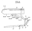
- the shape and operation of this mechanism 31, 32 with rods and shock absorbers is shown diagrammatically in FIG. 6.
- the lower position of the shelf 30 in FIG. 6 corresponds to the position that this shelf takes when it is retracted under the cushion. 33, that is to say as shown in FIG. 3.
- the upper position of the shelf 30 in FIG. 6 corresponds on the contrary to its position of use in abutment on the armrests 1a, 1b or it extends horizontally forward of the backrest 7, as shown moreover in FIGS. 2 and 4.
- Each connecting rod 31 is bent to adapt to the specific shape of the structure 9 of the seat and of the seat cushion 33, in particular twice bent in the same direction, as shown in Figure 6.
- the mechanism 31, 32 with connecting rods and dampers shown comprises two sets of connecting rod 31 and damper 32 similar and articulated to the same axes or along aligned or merged axes 34, 35, 36, 37.
- the mechanism 31, 32 with connecting rods and dampers is arranged substantially in the middle position with respect to the seat delimited by the two armrests 1a, 1b and with respect to the tablet 30.
- the structure 9 of the seat comprises a median curved bracket 38 which extends in the longitudinal median vertical plane P, and which supports at its upper free end a shaft 34 forming on the one hand an axis of pivoting for each of the connecting rods 31, and on the other hand axis 14 of articulation of the backrest 7, in particular of each half-backrest 7a, 7b at the seat 4.
- the backrest 7 between the two armrests 1a, 1b intermediate and central consists of half-files 7a, 7b which can be used either secured to one another or respectively secured to the backrest 6, 8 which immediately adjoins them.
- the shaft 34 carried by the bracket 38 supports on either side of this bracket 38 on the one hand each half-folder 7a, 7b and on the other hand a connecting rod 31 of articulation of the shelf 30.
- the bracket 38 also supports at a lower level, the pivot axis 37 of each of the shock absorbers 32 relative to the structure 9, by means of brackets or transverse rods 45 integral with this bracket 38 which is itself integral of the seat structure 9.
- the seat cushions 33 of airplane seats are generally easily removable and associated with the structure 9 of the seat by staples, or pressures or VELCRO (registered trademark) or other bands.
- VELCRO registered trademark
- to go from the tourist version to the first class version it suffices to remove this seat cushion 33, to reassemble the tablet 30 in the upper position above the armrests 1a, 1b, to bring the armrests 1a together, 1b after having unlocked them from the position where they are separated from each other, let the tablet 30 rest in abutment on each of these armrests 1a, 1b close together, and put the seat cushion 33 back.
- the same operations are carried out in reverse. These operations are illustrated in FIG. 5.
- an armrest has a rear part 39a, 39b close to the backrest 7 furnished with a comfort cushion and a front part 40a, 40b free of such a comfort cushion and which can support various accessories such as ashtray ...
- the tablet 30 is cut to bear on the front parts 40a, 40b of the armrests 1a, 1b leaving the rear parts 39a, 39b of the armrests furnished with comfort cushion free and usable. In this way, the tablet 30 does not interfere with the normal use of the armrests 1a, 1b when it is supported on these armrests.
- this shelf 30 can simply consist of a thin rigid plate of suitable shape. It can therefore be easily accommodated under the seat cushion 33, due to its small thickness.
- the front part 45 of the tablet 30 intended to rest in abutment on the front parts 40a, 40b of the armrests 1a, 1b is therefore wider than and projecting laterally with respect to the rear part 46 of the tablet 30 facing the posterior parts 39a, 39b of the armrests 1a, 1b.
- the folder 7 in the central square can be made up of half-folders 7a, 7b.
- a locking device 41, 42, 43, 44 is provided to secure each half-folder either to each other, or respectively to the folder which adjoins it.
- This blocking device can consist of an axis 41 sliding transversely horizontally inside each half-folder 7a, 7b and capable of penetrating either into an orifice 44 of the other half-folder 7b, 7a, or into a orifice 43 of the backrest 6, 8 forming the seat located immediately next to it.
- a control lever 42 can be provided along the upright of each half-backrest 7a, 7b, so as to be accessible from the outside, even when the backrest trim cushions are in place.
- the lever 42 cooperates with the axis 41 by means of a device of the threading / tapping type to control the transverse movement of this axis 41 in one direction or another when the lever 42 is tilted from one position higher than a lower position.
- a device of the threading / tapping type to control the transverse movement of this axis 41 in one direction or another when the lever 42 is tilted from one position higher than a lower position.
- the invention is advantageously applicable in the field of air transport to provide a convertible, light, low cost, high comfort, and perfectly aesthetic convertible seat in each of the tourist or first class or business class versions in which it is used. .
- the preferred embodiment described above of a three-seater seat in tourist version is given only by way of non-limiting example.
- the invention is applicable for making a seat with two seats convertible into one place, only the central armrest being articulated to be movable horizontally, or even for making a seat with more than three places.
Landscapes
- Engineering & Computer Science (AREA)
- Aviation & Aerospace Engineering (AREA)
- Transportation (AREA)
- Mechanical Engineering (AREA)
- Seats For Vehicles (AREA)
Abstract
Description
- L'invention concerne un siège de passagers de véhicule de transport en commun, notamment d'avion de ligne, du type définissant une pluralité de places dont au moins une est délimitée latéralement par deux accoudoirs écartés l'un de l'autre, et qui peut être utilisée soit en tant que place assise, soit pour le confort des passagers des autres places assises jouxtant cette place. Le besoin s'est fait sentir de pouvoir disposer d'un siège convertible selon les conditions d'utilisations souhaitées entre une version dite touriste où il procure le plus grand nombre de places et moins de confort, et une version dite première classe ou classe affaire où il procure le plus grand confort et moins de places assises.
- La demande de brevet EP-A-0335018 mentionne déjà un tel siège convertible dans lequel une tablette centrale est articulée par des bras à la structure du siège et peut être soit placée sur les accoudoirs centraux rapprochés, soit escamotée dans le dossier ou dans l'assise de la place centrale. La demande de brevet EP-A-0227239 décrit par ailleurs un mécanisme d'articulation des accoudoirs à la structure. Néanmoins ce mécanisme n'autorise que deux positions, pour les accoudoirs, et ne procure pas un verrouillage suffisament fiable dans chaque position. De plus, les articulations autour d'axes horizontaux subissent des contraintes et une usure importantes affectant la longévité du mécanisme. Egalement, lors manoeuvres, la hauteur des accoudoirs est modifiée, ce que oblige à tenir la tablette surélevée et empêche l'utilisation de tablettes de largeurs diverses. Par ailleurs, la résistance et la rigidité du mécanisme sont insuffisantes en paratique.
- L'invention a donc objet de pallier ces inconvénients, en proposant un tel siège de passagers de véhicule de transport en commun qui soit convertible aisément et rapidement entre une version touriste dans laquelle il propose un nombre maximum de places, et une version première classe ou classe affaire dans laquelle il propose une place en moins mais plus d'espace pour les autres places, et que incorpore un mécanisme de conversion léger, simple et peu onéreux tout en étant simultanément fiable, sûr et résistant. Plus précisément, l'invention vise à proposer un mécanisme permettant un verrouillage dans chaque position extrême ou dans des positions intermédiaires des accoudoirs, la largeur entre les accoudoirs pouvant être adaptée et modifiée selon notamment celle de la tablette.
- L'invention a aussi pour objet de proposer un tel siège pourvu d'une tablette de confort dite cocktail, qui, en version première classe ou classe affaire, jouxte une place assise à hauteur des accoudoirs, et qui, en version touriste, est inutilisée et intégrée et escamotée sans être encombrante, ni apparente, ni gêner les passagers, ni diminuer le confort à écart longitudinal constant entre les sièges. En particulier, l'invention a pour object de proposer un siège d'avion de ligne définissant trois places en version touriste et deux places et une tablette centrale en version première classe.
- L'invention a aussi pour objet de proposer un tel siège dont la conversion peut être effectuée sans outil, quasiment instantanément, et sans nuire aux autres caractéristiques du siège, notamment aux caractéristiques mécaniques, de sécurité, ou de confort.
- Egalement, l'invention a pour objet de proposer un tel siège qui :
. offre le même confort pour la place convertible que pour les autres en version touriste, et un véritable confort accru en version première classe, sur toute la largeur des places. . offre un confort équivalent à celui des sièges non convertibles, notamment du point de vue de l'espace longitudinal. . ait un esthétisme au moins équivalent, voire meilleur que les siège classiques non convertibles, en version touriste comme en version première classe, le caractère convertible du siège n'étant pas apparent. - Pour ce faire, l'invention concerne un siège de passagers de véhicule de transport en commun, notamment d'avion de ligne, du type définissant une pluralité de places assises dont au moins une est délimitée latéralement par deux accoudoirs, au moins un des deux accoudoirs étant associé à la structure du siège de façon à pouvoir être déplacé au moins entre une position où il est plus écarté de l'autre accoudoir et une position où il est plus rapproché de cet autre accoudoir, de sorte que la distance entre les deux accoudoirs peut être modifiée, une tablette formant plateau pouvant être placée dans une position d'utilisation en appui sur les deux accoudoirs lorsqu'ils sont rapprochés l'un de l'autre, caractérisé en ce que chaque accoudoir associé à la structure de façon à pouvoir être déplacé en translation, y est articulé par un mécanisme à bielles qui astreint l'accoudoir à conserver la même orientation longitudinale et la même hauteur lors de sa translation transversale au moins sensiblement horizontale entre deux positions.
- Selon l'invention, chacun des deux accoudoirs en question est associé à la structure du siège par un mécanisme à bielles de façon à pouvoir être déplacé en translation transversale au moins sensiblement horizontale, les deux mécanismes à bielles ayant une configuration symétrique l'un de l'autre par rapport au plan longitudinal médian P de la place assise délimitée entre les deux accoudoirs. Chaque mécanisme à bielles est constitué de deux bielles rigides et qui sont au moins sensiblement de mêmes longueur, forme, parallèles l'une à l'autre, et qui sont associées pivotantes à la structure du siège respectivement autour de deux axes de pivotement distincts au moins sensiblement verticaux, et à l'accoudoir autour de deux axes distincts au moins sensiblement verticaux, de façon à former un système déformable, notamment du type parallèlogramme déformable, imposant à l'accoudoir de conserver la même orientation générale. Les deux bielles sont coudées afin de ménager le maximum d'espace en largeur aux places assises, notamment aux places latérales lorsque les accoudoirs sont rapprochés l'un de l'autre. Les bielles sont associées à la structure au moins au voisinage de l'axe d'articulation du dossier à l'assise entre les deux dossiers séparés par l'acccoudoir, et par ailleurs sous la face inférieure de l'accoudoir correspondant. Les bielles s'étendent globalement inclinées vers le haut et vers l'avant à partir de leurs axes de pivotement et d'association à la structure. De la sorte, elles ne gênent pas les passagers et ne sont quasiment pas apparentes. Le mécanisme à bielles comporte un dispositif de blocage de l'accoudoir dans chacune des positions extrêmes ou intermédiaires plus rapproché ou plus écarté qu'il peut ou doit prendre. Ce dispositif de blocage est constitué par une extension de l'une des bielles au-delà de son axe de pivotement d'association à l'accoudoir, et par un têton porté par ladite extension et coopérant avec des lumières ménagées dans l'accoudoir pour le bloquer dans chaque position extrême ou intermédiaire.
- Selon l'invention, la tablette formant plateau est associée articulée par un mécanisme à la structure du siège entre les deux accoudoirs de façon à pouvoir être placée dans une position escamotée sous le coussin amovible de l'assise, et déplacée entre les positions escamotée et en appui sur les accoudoirs lorsque ceux-ci sont écartés l'un de l'autre.
- Selon l'invention, le mécanisme d'articulation de la tablette à la structure comporte au moins une bielle coudée associée à la structure par un axe de pivotement au moins sensiblement horizontal et confondu ou au voisinage de l'axe d'articulation du dossier à l'assise du siège, et sous la tablette par un axe de pivotement au moins sensiblement horizontal. Le mécanisme comporte également au moins un amortisseur fluide associé articulé à la bielle par un axe de pivotement au moins sensiblement horizontal situé au voisinage de l'axe de pivotement de la bielle par rapport à la structure. L'amortisseur est associé à la structure par un axe de pivotement inférieur au moins sensiblement horizontal. Le mécanisme à bielles comporte deux ensembles bielles et amortisseurs semblables et articulés aux mêmes axes ou à des axes alignés les uns aux autres. Le mécanisme à bielles et amortisseurs est disposé sensiblement en position médiane par rapport à la place assise délimitée par les deux accoudoirs , et par rapport à la tablette. La tablette est découpée pour prendre appui sur les parties antérieures des accoudoirs en laissant libres et utilisables les parties postérieures des accoudoirs garnies de coussins de confort. En combinaison avec ces caractéristiques le dossier de la place assise délimitée entre les deux accoudoirs est constitué de deux demi-dossiers qui peuvent être utilisés soit solidaires l'un de l'autre, soit solidaires respectivement du dossier qui les jouxte immédiatement.
- Ainsi, l'invention fournit un siège convertible d'une version touriste à une version première classe ou classe affaire et réciproquement. En version touriste, les deux accoudoirs sont écartés au maximum l'un de l'autre, et la tablette est escamotée sous le coussin d'assise de la place centrale délimitée par les accoudoirs. En version première classe ou classe affaire, les deux accoudoirs sont au contraire rapprochés l'un de l'autre à la largeur de la table, ménageant ainsi une plus grande largeur pour les places assises latérales jouxtant immédiatement les accoudoirs de chaque côté de la place assise centrale, et la tablette est placée en appui au-dessus des deux accoudoirs rapprochés pour le confort des deux passagers situés de part et d'autre de la tablette. Le mécanisme de conversion est simple et rigide et permet l'utilisation de tablettes de différentes largeurs.
- D'autres caractéristiques et avantages de l'invention apparaîtront à la lecture de la description suivante qui se référe aux figures annexées dans lesquelles :
- . La figure 1 est une vue en perspective d'un siège trois places en version touriste selon l'invention.
- . La figure 2 est une vue en perspective d'un siège trois places en version première classe ou classe affaire selon l'invention.
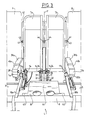
- . La figure 3 est une vue de face illustrant la position des accoudoirs et de la tablette centrale d'un siège selon l'invention en version touriste, les coussins de confort ayant été ôtés.
- . La figure 4 est une vue de face illustrant la position des accoudoirs et de la tablette centrale d'un siège selon l'invention en version première classe ou classe affaire, les coussins de confort ayant été ôtés.
- . La figure 5 est une vue schématique en perspective illustrant les mouvements de la tablette et des accoudoirs d'un siège selon l'invention lors du passage de la version touriste à la version première classe et réciproquement.
- . La figure 6 est une vue schématique partielle de profil illustrant le mécanisme à bielles et amortisseurs d'articulation de la tablette d'un siège selon l'invention.
- . La figure 7 est une vue schématique partielle de dessous illustrant les mécanismes à bielles d'articulation des accoudoirs à la structure d'un siège selon l'invention, les accoudoirs étant représentés en position rapprochés l'un de l'autre.
- L'invention concerne un siège de passagers de véhicule de transport en commun, notamment d'avion de ligne, du type définissant une pluralité de places assises dont au moins une est délimitée latéralement par deux accoudoirs 1a, 1b. Sur les figures, on a représenté à titre d'exemple non limitatif un siège de passager d'avion de ligne selon l'invention définissant normalement trois places assises en version touriste (figure 1), et deux places assises en version première classe (figure 2). Le siège selon l'invention est donc convertible entre la version représentée sur la figure 1 et celle représentée sur la figure 2 et vice-versa. L'invention permet néanmoins de réaliser de façon similaire des sièges définissant plus de places assises ou même un siège comportant deux places en version touriste et une seule place en version première classe.
- Le siège selon l'invention représenté sur les figures comporte donc deux accoudoirs 2a, 2b extrêmes associés rigidement et fixes par rapport à la structure du siège de façon connue, et deux accoudoirs centraux 1a, 1b délimitant d'une part normalement en version touriste und place assise centrale entre ces deux accoudoirs centraux 1a, 1b, et d'autre part, de chaque côte, et avec chacun des accoudoirs 2a, 2b, respectivement deux places assises latérales disposées de part et d'autre de la place assise centrale. Le siège représenté forme donc une banquette constituée de trois assises 3, 4, 5 garnies de coussins d'assise amovibles, et de trois dossiers 6, 7, 8 garnis également de coussins de dossier amovibles, de façon connue en soi.
- Le siège est par ailleurs constitué d'une structure 9 formant ossature de support des différents coussins et des différents éléments de fonctionnement de ce siège. La structure générale d'un tel siège est connue, et seuls les éléments propres à l'invention seront donc décrits en détail.
- L'invention concerne donc un siège de passager de véhicule de transport en commun, notamment d'avion de ligne, du type définissant une pluralité de places assises dont au moins une est délimitée latéralement par deux accoudoirs 1a, 1b, caractérisé en ce qu'au moins un des deux accoudoirs 1a, 1b est associé à la structure 9 du siège de façon à pouvoir être déplacé en translation transversale au moins sensiblement horizontale au moins entre une position où il est plus écarté de l'autre accoudoir, et une position où il est plus rapproché de cet autre accoudoir, de sorte que la distance entre les deux accoudoirs 1a, 1b peut être modifiée, notamment selon que la place entre ces deux accoudoirs 1a, 1b est destinée à être occupée par un passager ou non. Le siège selon l'invention comporte une tablette 30 formant plateau associée articulée à la structure 9 du siège entre les deux accoudoirs 1a, 1b par un mécanisme 31, 32 à bielles et amortisseurs de façon à pouvoir être placée dans une position d'utilisation en appui sur les deux accoudoirs 1a, 1b rapprochés l'un de l'autre, ou dans une position escamotée sous le coussin amovible 33 de l'assise 4, et déplacée entre ces deux positions lorsque les deux accoudoirs 1a, 1b sont écartés l'un de l'autre. Chacun des accoudoirs 1a, 1b qui est associé à la structure 9 de façon à pouvoir être déplacé en translation comme mentionné précédemment, y est articulé par un mécanisme à bielles 10a, 10b, 11a, 11b.
- Contrairement à ce qui est préconisé par l'art antérieur, l'inventeur a mis en évidence que le fait de prévoir la tablette 30 cocktail escamotée dans l'assise 4 du siège offre des avantages prépondérants, peut être réalisé de façon simple du point de vue mécanique sans gréver le coût et le poids du siège, et est facile à utiliser.
- Selon l'invention, chacun des accoudoirs 1a, 1b central de séparation de places assises, c'est-à-dire chacun des accoudoirs 1a, 1b autres que les accoudoirs fixes d'extrêmité 2a, 2b, est associé à la structure 9 du siège de façon à pouvoir être déplacé en translation transversale au moins sensiblement horizontale comme mentionné précédemment. Ainsi, dans le mode de réalisation représenté, chacun des deux accoudoirs 1a, 1b centraux délimitant la place centrale est articulé à la structure 9 par un mécanisme à bielles 10a, 10b, 11a, 11b qui lui est propre de façon à pouvoir être déplacé en translation transversale au moins sensiblement horizontale comme mentionné précédemment, les deux mécanismes à bielles 10a, 10b, 11a, 11b ayant des configurations symétriques l'une de l'autre par rapport au plan vertical longitudinal médian P de la place assise délimitée entre les deux accoudoirs 1a, 1b. Néanmoins, un seul des accoudoirs 1a, 1b délimitant la place assise peut être articulé de façon mobile par un tel mécanisme à bielles 10a, 10b, 11a, 11b à la structure 9 du siège, notamment dans le cas d'un siège formant normalement en version touriste uniquement deux places assises.
- La description suivante du mécanisme à bielles 10a, 10b, 11a, 11b n'est donnée que pour un des deux accoudoirs 1a, 1b, les mêmes dispositions s'appliquant aussi à l'autre accoudoir 1b, 1a dans le cas d'un siège à au moins trois places assises tel que représenté.
- Selon l'invention, le mécanisme à bielles 10a, 10b, 11a, 11b astreint l'accoudoir 1a, 1b correspondant à conserver la même orientation longitudinale (c'est-à-dire au moins sensiblement perpendiculaire au dossier 7), et au moins sensiblement la même hauteur, lors de sa translation. Chaque mécanisme à bielles 10a, 10b, 11a, 11b est constitué de deux bielles rigides 10a, 11a respectivement 10b, 11b qui sont au moins sensiblement de mêmes longueur, forme, et parallèles l'une à l'autre, et qui sont associées pivotantes à la structure 9 respectivement autour de deux axes de pivotement 12a, 12b distincts au moins sensiblement verticaux. Les deux bielles sont également associées pivotantes à l'accoudoir correspondant 1a respectivement 1b autour de deux axes de pivotement 13a, 13b distincts au moins sensiblement verticaux. Chacune des deux bielles 10a, 10b, 11a, 11b, est donc articulée à chacune de ses extrémités. Ainsi, pour chaque accoudoir 1a, 1b le mécanisme à bielles 10a, 10b, 11a, 11b forme un système déformable du type parallèlogramme déformable, imposant à l'accoudoir 1a, 1b correspondant de conserver la même orientation longitudinale et la même hauteur lors de la translation horizontale transversale. Les deux bielles 10a, 10b, 11a, 11b d'une mécanisme à bielles d'articulation d'un accoudoir 1a, 1b sont coudées (figure 7) à convexité orientée vers la place assise centrale délimitée par les accoudoirs 1a, 1b, et ce afin de ne pas gêner les passagers des places latérales situées de part et d'autre en version première classe. Les bielles 10a, 10b, 11a, 11b sont associées à la structure 9 du siège au moins au voisinage de l'axe géométrique d'articulation 14 du dossier 7 à l'assise 4 et entre les dossiers 6, 7 ou 7, 8 des places assises séparées par l'accoudoir 1a ou 1b. Les bielles 10a, 10b, 11a, 11b sont associées par ailleurs sous la face inférieure 15a, 15b de l'accoudoir correspondant 1a, 1b.
- Chacun des axes de pivotement 12a, 12b, 13a, 13b d'une bielle 10a, 10b, 11a, 11b est formé d'un alésage vertical débouchant ménagé à chacune des extrémités libres 16a, 16b, 17a, 17b de la bielle, et d'un boulon 12a, 12b, 13a, 13b serré dans cet alésage et coopérant avec un taraudage vertical ménagé dans un support 20a, 20b de la structure 9 du siège ou dans l'accoudoir 1a, 1b. Des coussinets ou des paliers appropriés peuvent être interposés entre chaque boulon 12, 13 et les alésages correspondant. Des dispositifs de blocage de chaque boulon 12, 13 en position serrée peuvent aussi être prévus (contre-écrou, goupille, rondelle...).
- Les bielles 10a, 10b, 11a, 11b s'étendent globalement inclinées par rapport à l'horizontale vers le haut et vers l'avant à partir de leurs axes de pivotement 13a, 13b d'association à la structure 9 au voisinage de l'axe géométrique d'articulation 14 du dossier 7 à l'assise 4. Les bielles 10a, 10b, 11a, 11b s'étendent inclinées entre chaque support 20a, 20b et la face inférieure 15a, 15b de l'accoudoir 1a, 1b correspondant. Chacun des supports 20a, 20b est formé à l'extrêmité arrière supérieure d'un longeron 18a, 18b séparant deux assises 3, 4 ou 4, 5. Les supports 20a, 20b sont situés ainsi au voisinage de l'axe 14 d'articulation des dossiers 6, 7, 8 aux assises 3, 4, 5.
- Par ailleurs, l'écartement transversal entre chacun des deux bielles 10a, 10b, 11a, 11b d'un même mécanisme à bielles est déterminé de façon qu'il soit suffisant pour permettre le mouvement de l'accoudoir 1a, 1b entre les deux positions extrêmes plus rapproché et plus écarté, sans pour autant conférer au dit mécanisme à bielles un encombrement trop important. En pratique, la course de déplacement de chaque accoudoir 1a, 1b est relativement faible, par exemple comprise entre 5 et 15 cm, notamment de l'ordre de 10cm. De ce fait, un écartement relativement limité, notamment de l'ordre de quelques centimètres, entre chacune des deux bielles est suffisant. Ainsi, cet écartement entre les deux bielles peut être en pratique inférieur à la largeur de chacun des accoudoirs 1a, 1b dans chacune des positions de cet accoudoir.
- Chaque mécanisme à bielles 10a, 10b, 11a, 11b propre à un accoudoir 1a, 1b comporte un dispositif de blocage 21a, 21b, 22a, 22b, 23a, 23b dudit accoudoir 1a, 1b dans chacune des positions -notamment extrêmes ou intermédiaires- plus rapproché ou plus écarté qu'il peut ou doit prendre. Ce dispositif de blocage 21a, 21b, 22a, 22b, 23a, 23b peut être commandé de l'extérieur par l'utilisateur pour d'une part bloquer l'accoudoir dans l'une et l'autre des positions extrêmes à volonté, et d'autre part, débloquer cet accoudoir à partir de chacune de ces positions en vue du passage d'une position à une autre lorsque l'on convertit le siège de la version touriste à la version première classe ou vice-versa. Un dispositif de blocage 21a, 21b, 22a, 22b, 23a, 23b selon l'invention est constitué par une extension 21a, 21b de l'extrémité libre 17a, 17b d'association à l'accoudoir 1a, 1b de l'une des bielles 10a, 10b au-delà de son axe de pivotement 13a, 13b d'association à l'accoudoir 1a, 1b (figure 7), et par un têton 22a, 22b porté par ladite extension 21a, 21b et coopérant avec des lumières 25a, 25b, 26a, 26b ménagées dans l'accoudoir 1a, 1b pour le bloquer dans chaque position extrême. L'extension 21a, 21b prolonge l'extrémité libre 17a, 17b horizontalement au-delà de l'axe de pivotement 13a, 13b sous la face inférieure 15a, 15b horizontale de l'accoudoir 1a, 1b. Chaque accoudoir 1a, 1b comporte au moins deux lumières 25a, 26a, respectivement 25b, 26b, dont l'une 25a, 25b permet le bloquage des accoudoirs 1a, 1b en position écartés l'un de l'autre, et dont l'autre 26a, 26b permet le blocage de ces accoudoirs 1a, 1b en position rapprochés l'un de l'autre. Les lumières 25a, 25b, 26a, 26b sont simplement ménagées à travers la face inférieure 15a, 15b de l'accoudoir 1a, 1b. Chacun des têtons 22a, 22b coopérant avec lesdites lumières est introduit dans un alésage vertical de l'extension 21a, 21b et saille verticalement vers le haut au-delà de cette extension 21a, 21b pour pénétrer dans les lumières 25a, 25b, 26a, 26b. Néanmoins, le têton 22a, 22b est associé à l'extension 21a, 21b de façon mobile pour pouvoir être dégagé verticalement et vers le bas de chaque lumière 25a, 25b, 26a, 26b à volonté. Pour ce faire, on peut prévoir par exemple que les extensions 21a, 21b soient creuses et renferment un ressort de compression coopérant avec une couronne en saillie radiale du têton 22a, 22b pour rappeler vers le haut ce têton 22a, 22b. Dans un tel cas, l'extension creuse 21a, 21b doit avoir au moins une paroi démontable pour permettre l'accès à et le montage d'un tel dispositif de rappel. Par ailleurs, le têton 22a, 22b saille également verticalement et vers le bas au-delà de l'extension 21a, 21b pour former un bouton 23a, 23b de préhension de ce têton 22a, 22b. Dans un tel mode de réalisation possible, les lumières 25a, 25b, 26a, 26b peuvent avoir une forme circulaire, ainsi que les extrémités supérieures des têtons 22a, 22b pénétrant dans ces lumières. Plusieurs lumières 25, 26 peuvent être prévues pour permettre le blocage des accoudoirs, dans des dispositions intermédiaires, selon la largeur de la tablette.
- Le siège selon l'invention peut être muni de tous les organes nécessaires par ailleurs à son bon fonctionnement. Ces organes connus sont supposés intégrés au siège selon l'invention, seuls les organes spécifiques à l'invention étant décrits en détail, notamment, les dossiers 6, 7, 8 sont articulés aux assises 3, 4, 5 autour d'un axe géométrique commun 14 d'articulation horizontal transversal, et l'inclinaison du dossier peut être réglé grâce à un vérin 27 commandé par un bouton de commande 28 relié au vérin 27 grâce à un câble de connexion 29. Le bouton 28 est porté de façon classique par un des accoudoirs 1a, 1b, et le câble 29 de connexion peut être inséré dans l'une des deux bielles creuses 10a, 10b, 11a, 11b du mécanisme d'association de l'accoudoir à la structure. Dans ce cas, le câble 29 de connexion du bouton 28 au vérin 27 peut être introduit dans l'accoudoir 1a, 1b à travers la face inférieure 15a, 15b au niveau de l'extrémité libre 17a, 17b portant l'axe de pivotement 13a, 13b, à travers une lumière ménagée à cet effet. Ainsi, ce câble 29 de connexion est caché, comme dans le cas des accoudoirs traditionnels.
- Le mécanisme 31, 32 à bielles et amortisseurs d'association de la tablette 30 à la structure 9 comporte au moins une bielle coudée 31 associée à la structure 9 par un axe de pivotement 34 au moins sensiblement horizontal et confondu ou au voisinage de l'axe géométrique d'articulation 14 du dossier 7 à l'assise 4 du siège. La bielle coudée 31 est associée sous la tablette 30 par un axe de pivotement 35 au moins sensiblement horizontal. Le mécanisme 31, 32 comporte par ailleurs au moins un amortisseur 32 fluide associé articulé à la bielle 31 par un axe de pivotement 36. Cet axe de pivotement 36 s'étend au moins sensiblement horizontalement et est situé au voisinage de l'axe de pivotement 34 de la bielle 31 par rapport à la structure 9. Par ailleurs, l'amortisseur 32 est associé articulé à la structure 9 par un axe de pivotement 37 inférieur qui s'étend également au moins sensiblement horizontalement. La forme et le fonctionnement de ce mécanisme 31, 32 à bielles et amortisseurs est représenté schématiquement sur la figure 6. La position inférieure de la tablette 30 sur la figure 6 correspond à la position que prend cette tablette lorsqu'elle est escamotée sous le coussin 33, c'est-à-dire comme représenté sur la figure 3. La position supérieure de la tablette 30 sur la figure 6 correspond au contraire à sa position d'utilisation en appui sur les accoudoirs 1a, 1b ou elle s'étend horizontalement vers l'avant du dossier 7, comme représenté par ailleurs sur les figures 2 et 4. Chaque bielle 31 est coudée pour s'adapter à la forme spéficique de la structure 9 du siège et du coussin d'assise 33, notamment deux fois coudée dans le même sens, comme représenté sur la figure 6.
- Le mécanisme 31, 32 à bielles et amortisseurs représenté comporte deux ensembles bielle 31 et amortisseur 32 semblables et articulés aux mêmes axes ou selon des axes alignés ou confondus 34, 35, 36, 37. Néanmoins, le mécanisme 31, 32 à bielles et amortisseurs est disposé sensiblement en position médiane par rapport à la place assise délimitée par les deux accoudoirs 1a, 1b et par rapport à la tablette 30.
- Comme représenté sur les figures 3 et 4, la structure 9 du siège comporte une potence 38 courbée médiane qui s'étend dans le plan P vertical médian longitudinal, et qui supporte à son extrémité libre supérieure un arbre 34 formant d'une part axe de pivotement pour chacune des bielles 31, et d'autre part axe 14 d'articulation du dossier 7, notamment de chaque demi-dossier 7a, 7b à l'assise 4. En effet, dans un siège selon l'invention, le dossier 7 entre les deux accoudoirs 1a, 1b intermédiaires et centraux, est constitué de demi-dossiers 7a, 7b qui peuvent être utilisés soit solidaires l'un de l'autre soit solidaires respectivement du dossier 6, 8 qui les jouxte immédiatement. Dans ce cas, l'arbre 34 porté par la potence 38 supporte de part et d'autre de cette potence 38 d'une part chaque demi-dossier 7a, 7b et d'autre part une bielle 31 d'articulation de la tablette 30. La potence 38 supporte également à un niveau inférieur, l'axe de pivotement 37 de chacun des amortisseurs 32 par rapport à la structure 9, grâce à des équerres ou tiges transversales 45 solidaires de cette potence 38 qui est elle-même solidaire de la structure 9 du siège.
- Les coussins d'assise 33 des sièges d'avion sont en général aisément amovibles et associés à la structure 9 du siège par des agrafes, ou des pressions ou des bandes VELCRO (marque déposée) ou autres. De la sorte, pour passer de la version touriste à la version première classe, il suffit d'enlever ce coussin d'assise 33, de remonter la tablette 30 en position supérieure au dessus des accoudoirs 1a, 1b, de rapprocher les accoudoirs 1a, 1b après les avoir débloqués de la position où ils sont écartés l'un de l'autre, de laisser la tablette 30 reposer en appui sur chacun de ces accoudoirs 1a, 1b rapprochés, et de remettre le coussin d'assise 33. Pour passer de la version première classe à la version touriste, les mêmes opérations sont effectuées en sens inverse. Ces opérations sont illustrées sur la figure 5.
- Généralement, un accoudoir comporte une partie postérieure 39a, 39b proche du dossier 7 garnie d'un coussin de confort et une partie antérieure 40a, 40b exempte d'un tel coussin de confort et qui peut supporter divers accessoires tels que cendrier ... Selon l'invention, la tablette 30 est découpée pour prendre appui sur les parties antérieures 40a, 40b des accoudoirs 1a, 1b en laissant libres et utilisables les parties postérieures 39a, 39b des accoudoirs garnies de coussin de confort. De la sorte, la tablette 30 ne gêne pas l'utilisation normale des accoudoirs 1a, 1b lorsqu'elle est en appui sur ces accoudoirs. De plus, cette tablette 30 peut être simplement constituée d'une plaque rigide mince de forme appropriée. Elle peut donc être logée facilement sous le coussin d'assise 33, du fait de son faible encombrement en épaisseur. La partie antérieure 45 de la tablette 30 destinée à reposer en appui sur les parties antérieures 40a, 40b des accoudoirs 1a, 1b est donc plus large que et en saillie latéralement par rapport à la partie postérieure 46 de la tablette 30 en regard des parties postérieures 39a, 39b des accoudoirs 1a, 1b.
- Comme déjà dit, le dossier 7 de la place centrale peut être constitué de demi-dossiers 7a, 7b. Un dispositif de blocage 41, 42, 43, 44 est prévu pour solidariser chaque demi-dossier soit l'un à l'autre, soit respectivement au dossier qui le jouxte. Ce dispositif de blocage peut être constitué d'un axe 41 coulissant transversalement horizontalement à l'intérieur de chaque demi-dossier 7a, 7b et susceptible de pénétrer soit dans un orifice 44 de l'autre demi-dossier 7b, 7a, soit dans un orifice 43 du dossier 6, 8 formant la place assise située immédiatement à côté. Un levier 42 de commande peut être prévu le long du montant de chaque demi-dossier 7a, 7b, de façon à être accessible de l'extérieur, même lorsque les coussins de garniture du dossier sont en place. Le levier 42 coopère avec l'axe 41 par l'intermédiaire d'un dispositif du type filetage/taraudage pour commander le déplacement transversal de cet axe 41 dans un sens ou dans un autre lorsque l'on bascule ce levier 42 d'une position supérieure à une position inférieure. Par exemple, dans la position du levier 42 représentée sur les figures 3 et 4 où il est orienté vers le haut, chacun des axes 41 des deux demi-dossiers 7a, 7b est engagé dans les orifices 43 des autres dossiers 6, 8. Au contraire, lorsque l'on abaisse les leviers 42 vers le bas, les axes 41 sortent des orifices de ces dossiers 6, 8 et l'un des axes 41 de l'un des demi-dossiers 7a, 7b pénètre dans l'orifice 44 de l'autre demi-dossier 7a, 7b.
- L'invention est avantageusement applicable dans le domaine du transport aérien pour proposer un siège multi-places convertible, léger, de faible côut, de grand confort, et parfaitement esthétique dans chacune des versions touriste ou première classe ou classe affaire dans laquelle il est utilisé. Le mode de réalisation préférentiel décrit ci-dessus d'un siège à trois places en version touriste n'est donné qu'à titre d'exemple non limitatif. Ainsi, l'invention est applicable pour réaliser un siège à deux places convertibles en une place, seul l'accoudoir central étant articulé pour être mobile horizontalement, ou encore pour réaliser un siège à plus de trois places.
Claims (13)
Applications Claiming Priority (2)
| Application Number | Priority Date | Filing Date | Title |
|---|---|---|---|
| FR8902662A FR2643870A1 (fr) | 1989-03-01 | 1989-03-01 | Siege de passagers convertible a tablette escamotable |
| FR8902662 | 1989-03-01 |
Publications (2)
| Publication Number | Publication Date |
|---|---|
| EP0385861A1 true EP0385861A1 (fr) | 1990-09-05 |
| EP0385861B1 EP0385861B1 (fr) | 1993-03-03 |
Family
ID=9379256
Family Applications (1)
| Application Number | Title | Priority Date | Filing Date |
|---|---|---|---|
| EP19900400557 Expired - Lifetime EP0385861B1 (fr) | 1989-03-01 | 1990-02-28 | Siège de passagers convertible à tablette escamotable |
Country Status (3)
| Country | Link |
|---|---|
| EP (1) | EP0385861B1 (fr) |
| DE (1) | DE69000982T2 (fr) |
| FR (1) | FR2643870A1 (fr) |
Cited By (10)
| Publication number | Priority date | Publication date | Assignee | Title |
|---|---|---|---|---|
| GB2249721B (en) * | 1989-04-06 | 1993-08-18 | Magerik Ltd | Seating |
| WO1995003969A1 (fr) * | 1993-07-29 | 1995-02-09 | Flight Equipment & Engineering Limited | Agencements d'accoudoirs dans des sieges convertibles pour passagers d'avion |
| WO1995029843A1 (fr) * | 1994-04-28 | 1995-11-09 | Flight Equipment & Engineering Limited | Accoudoirs de rangees transformables en deux ou trois sieges pour passagers d'avion |
| EP0933249A1 (fr) | 1998-01-30 | 1999-08-04 | Societe Industrielle Et Commerciale De Materiel Aeronautique (Sicma) Societe Anonyme | Dispositif d'articulation démontable, structure de siège, siège et véhicule équipé de ce dispositif |
| WO2001010671A1 (fr) * | 1999-08-07 | 2001-02-15 | Aguti Produktentwicklung & Design Gmbh | Dispositif de rangement monte sur un siege de vehicule |
| EP1566335A1 (fr) * | 2004-02-18 | 2005-08-24 | Recaro Aircraft Seating GmbH & Co.KG. | Rangée de sièges convertible pour avion |
| WO2009112673A1 (fr) * | 2008-01-17 | 2009-09-17 | Airbus | Dispositif pour tablette et siège escamotables |
| US9132918B2 (en) | 2009-01-30 | 2015-09-15 | Air New Zealand Limited | Seating arrangement, seat unit, tray table and seating system |
| FR3066083A1 (fr) * | 2017-05-12 | 2018-11-16 | Peugeot Citroen Automobiles Sa | Table escamotable en tissu a mecanisme de type enrouleur |
| CN112061401A (zh) * | 2019-06-10 | 2020-12-11 | B/E航空公司 | 飞机座椅可展开桥式桌、安装装置和储存装置 |
Families Citing this family (3)
| Publication number | Priority date | Publication date | Assignee | Title |
|---|---|---|---|---|
| DE102005042376A1 (de) | 2005-09-07 | 2007-03-08 | Recaro Aircraft Seating Gmbh & Co. Kg | Sitzsystem für Fahrzeuge zur Personenbeförderung, insbesondere für Luftfahrzeuge |
| USD665182S1 (en) | 2010-01-14 | 2012-08-14 | Air New Zealand Limited | Aircraft seat unit |
| DE102018006514A1 (de) * | 2018-08-17 | 2020-02-20 | Airbus Operations Gmbh | Sitzgruppenanordnung für eine Passagierkabine eines Flugzeuges |
Citations (4)
| Publication number | Priority date | Publication date | Assignee | Title |
|---|---|---|---|---|
| US4307913A (en) * | 1980-06-02 | 1981-12-29 | Milsco Manufacturing Company | Adjustable arm-rest for vehicle seat |
| EP0227239A1 (fr) * | 1985-10-18 | 1987-07-01 | FLIGHT EQUIPMENT & ENGINEERING LIMITED | Sièges à largeur variable pour véhicules |
| EP0294086A1 (fr) * | 1987-06-01 | 1988-12-07 | FLIGHT EQUIPMENT & ENGINEERING LIMITED | Sièges réglables en largeur pour véhicules de transport |
| EP0335018A1 (fr) * | 1988-03-29 | 1989-10-04 | FLIGHT EQUIPMENT & ENGINEERING LIMITED | Assemblage d'accoudoir pour siège de véhicule |
-
1989
- 1989-03-01 FR FR8902662A patent/FR2643870A1/fr active Pending
-
1990
- 1990-02-28 EP EP19900400557 patent/EP0385861B1/fr not_active Expired - Lifetime
- 1990-02-28 DE DE1990600982 patent/DE69000982T2/de not_active Expired - Fee Related
Patent Citations (4)
| Publication number | Priority date | Publication date | Assignee | Title |
|---|---|---|---|---|
| US4307913A (en) * | 1980-06-02 | 1981-12-29 | Milsco Manufacturing Company | Adjustable arm-rest for vehicle seat |
| EP0227239A1 (fr) * | 1985-10-18 | 1987-07-01 | FLIGHT EQUIPMENT & ENGINEERING LIMITED | Sièges à largeur variable pour véhicules |
| EP0294086A1 (fr) * | 1987-06-01 | 1988-12-07 | FLIGHT EQUIPMENT & ENGINEERING LIMITED | Sièges réglables en largeur pour véhicules de transport |
| EP0335018A1 (fr) * | 1988-03-29 | 1989-10-04 | FLIGHT EQUIPMENT & ENGINEERING LIMITED | Assemblage d'accoudoir pour siège de véhicule |
Cited By (16)
| Publication number | Priority date | Publication date | Assignee | Title |
|---|---|---|---|---|
| GB2249721B (en) * | 1989-04-06 | 1993-08-18 | Magerik Ltd | Seating |
| WO1995003969A1 (fr) * | 1993-07-29 | 1995-02-09 | Flight Equipment & Engineering Limited | Agencements d'accoudoirs dans des sieges convertibles pour passagers d'avion |
| WO1995029843A1 (fr) * | 1994-04-28 | 1995-11-09 | Flight Equipment & Engineering Limited | Accoudoirs de rangees transformables en deux ou trois sieges pour passagers d'avion |
| WO1995029844A1 (fr) * | 1994-04-28 | 1995-11-09 | Flight Equipment & Engineering Limited | Rangee de sieges transformable pour passagers d'avion |
| EP0933249A1 (fr) | 1998-01-30 | 1999-08-04 | Societe Industrielle Et Commerciale De Materiel Aeronautique (Sicma) Societe Anonyme | Dispositif d'articulation démontable, structure de siège, siège et véhicule équipé de ce dispositif |
| FR2774356A1 (fr) | 1998-01-30 | 1999-08-06 | Sicma Aero Seat | Dispositif d'articulation demontable, structure de siege, siege et vehicule equipe de ce dispositif |
| WO2001010671A1 (fr) * | 1999-08-07 | 2001-02-15 | Aguti Produktentwicklung & Design Gmbh | Dispositif de rangement monte sur un siege de vehicule |
| EP1566335A1 (fr) * | 2004-02-18 | 2005-08-24 | Recaro Aircraft Seating GmbH & Co.KG. | Rangée de sièges convertible pour avion |
| WO2009112673A1 (fr) * | 2008-01-17 | 2009-09-17 | Airbus | Dispositif pour tablette et siège escamotables |
| CN101909935B (zh) * | 2008-01-17 | 2012-11-07 | 空中客车公司 | 用于可收放式的小桌及座具的装置 |
| US9102409B2 (en) | 2008-01-17 | 2015-08-11 | Airbus | Device for retractable tablet and seat |
| US9132918B2 (en) | 2009-01-30 | 2015-09-15 | Air New Zealand Limited | Seating arrangement, seat unit, tray table and seating system |
| FR3066083A1 (fr) * | 2017-05-12 | 2018-11-16 | Peugeot Citroen Automobiles Sa | Table escamotable en tissu a mecanisme de type enrouleur |
| CN112061401A (zh) * | 2019-06-10 | 2020-12-11 | B/E航空公司 | 飞机座椅可展开桥式桌、安装装置和储存装置 |
| EP3750806A1 (fr) * | 2019-06-10 | 2020-12-16 | Be Aerospace, Inc. | Table de pontage déployable pour siège d'avion, dispositions de montage et dispositions de stockage |
| CN112061401B (zh) * | 2019-06-10 | 2024-05-07 | B/E航空公司 | 飞机座椅可展开桥式桌、安装装置和储存装置 |
Also Published As
| Publication number | Publication date |
|---|---|
| DE69000982D1 (de) | 1993-04-08 |
| EP0385861B1 (fr) | 1993-03-03 |
| FR2643870A1 (fr) | 1990-09-07 |
| DE69000982T2 (de) | 1993-09-09 |
Similar Documents
| Publication | Publication Date | Title |
|---|---|---|
| CA3033918C (fr) | Arrangement de sieges, notamment d'un avion | |
| EP1345810B1 (fr) | Fauteuil convertible en lit, notamment pour aeronef | |
| EP2878481B1 (fr) | Siège passager à structure baquet et position ajustable | |
| EP0385861B1 (fr) | Siège de passagers convertible à tablette escamotable | |
| EP1731351B1 (fr) | Accoudoir central pour sièges latéraux | |
| FR2941656A3 (en) | Seating arrangement, seat unit and seating system | |
| FR2888541A1 (fr) | Banquette arriere de vehicule automobile | |
| CH626522A5 (en) | Tilting mounting for a chair seat | |
| EP0755860A1 (fr) | Siège transformable en couchette pour aéronef | |
| EP0575243B1 (fr) | Perfectionnements aux sièges de véhicules à réglages multiples | |
| EP1152918A1 (fr) | Siege pour enfant, a dossier reglable en largeur | |
| EP0343026A2 (fr) | Agencement d'un siège sur un plancher de véhicule | |
| FR2625423A1 (fr) | Perfectionnements apportes aux canapes-lits | |
| EP0231698B1 (fr) | Perfectionnements aux sièges rabattables de véhicules | |
| EP1537805B1 (fr) | Ensemble de rélaxation pour l'ameublement ou l'automobile, du type canapé, fauteil ou siège transformable, pouvant fonctionner en étant positionne directement contre une paroi | |
| FR2832676A1 (fr) | Siege de vehicule automobile a console integree | |
| FR3115267A1 (fr) | Amenagement interieur d'une cabine d'aeronef et procede associe | |
| EP0161157A1 (fr) | Siège transformable en couchette | |
| FR2828150A1 (fr) | Siege d'automobile comportant un dossier rabattable a largeur variable | |
| FR2754496A1 (fr) | Siege pour vehicule automobile ayant une assise reglable en longueur | |
| FR2593366A1 (fr) | Siege a dossier inclinable, notamment siege arriere de vehicule automobile | |
| FR3045547A1 (fr) | Voiture de transport public a capacite d'accueil amelioree | |
| FR2651658A1 (fr) | Siege de repos repliable, notamment pour enfant. | |
| WO2002069756A1 (fr) | Bureau monobloc reglable | |
| FR2641453A1 (fr) | Fauteuil de repos |
Legal Events
| Date | Code | Title | Description |
|---|---|---|---|
| PUAI | Public reference made under article 153(3) epc to a published international application that has entered the european phase |
Free format text: ORIGINAL CODE: 0009012 |
|
| AK | Designated contracting states |
Kind code of ref document: A1 Designated state(s): DE FR GB IT |
|
| 17P | Request for examination filed |
Effective date: 19901214 |
|
| 17Q | First examination report despatched |
Effective date: 19920330 |
|
| GRAA | (expected) grant |
Free format text: ORIGINAL CODE: 0009210 |
|
| AK | Designated contracting states |
Kind code of ref document: B1 Designated state(s): DE FR GB IT |
|
| ITF | It: translation for a ep patent filed |
Owner name: BUGNION S.P.A. |
|
| REF | Corresponds to: |
Ref document number: 69000982 Country of ref document: DE Date of ref document: 19930408 |
|
| GBT | Gb: translation of ep patent filed (gb section 77(6)(a)/1977) |
Effective date: 19930423 |
|
| PLBE | No opposition filed within time limit |
Free format text: ORIGINAL CODE: 0009261 |
|
| STAA | Information on the status of an ep patent application or granted ep patent |
Free format text: STATUS: NO OPPOSITION FILED WITHIN TIME LIMIT |
|
| 26N | No opposition filed | ||
| PGFP | Annual fee paid to national office [announced via postgrant information from national office to epo] |
Ref country code: FR Payment date: 20010112 Year of fee payment: 12 |
|
| PGFP | Annual fee paid to national office [announced via postgrant information from national office to epo] |
Ref country code: DE Payment date: 20010210 Year of fee payment: 12 |
|
| PGFP | Annual fee paid to national office [announced via postgrant information from national office to epo] |
Ref country code: GB Payment date: 20010215 Year of fee payment: 12 |
|
| REG | Reference to a national code |
Ref country code: GB Ref legal event code: IF02 |
|
| PG25 | Lapsed in a contracting state [announced via postgrant information from national office to epo] |
Ref country code: GB Free format text: LAPSE BECAUSE OF NON-PAYMENT OF DUE FEES Effective date: 20020228 |
|
| PG25 | Lapsed in a contracting state [announced via postgrant information from national office to epo] |
Ref country code: DE Free format text: LAPSE BECAUSE OF NON-PAYMENT OF DUE FEES Effective date: 20020903 |
|
| GBPC | Gb: european patent ceased through non-payment of renewal fee |
Effective date: 20020228 |
|
| PG25 | Lapsed in a contracting state [announced via postgrant information from national office to epo] |
Ref country code: FR Free format text: LAPSE BECAUSE OF NON-PAYMENT OF DUE FEES Effective date: 20021031 |
|
| REG | Reference to a national code |
Ref country code: FR Ref legal event code: ST |
|
| PG25 | Lapsed in a contracting state [announced via postgrant information from national office to epo] |
Ref country code: IT Free format text: LAPSE BECAUSE OF NON-PAYMENT OF DUE FEES;WARNING: LAPSES OF ITALIAN PATENTS WITH EFFECTIVE DATE BEFORE 2007 MAY HAVE OCCURRED AT ANY TIME BEFORE 2007. THE CORRECT EFFECTIVE DATE MAY BE DIFFERENT FROM THE ONE RECORDED. Effective date: 20050228 |