EP0385359B1 - Magnetic head - Google Patents
Magnetic head Download PDFInfo
- Publication number
- EP0385359B1 EP0385359B1 EP90103718A EP90103718A EP0385359B1 EP 0385359 B1 EP0385359 B1 EP 0385359B1 EP 90103718 A EP90103718 A EP 90103718A EP 90103718 A EP90103718 A EP 90103718A EP 0385359 B1 EP0385359 B1 EP 0385359B1
- Authority
- EP
- European Patent Office
- Prior art keywords
- tape
- magnetic
- magnetic tape
- magnetic head
- traveling
- Prior art date
- Legal status (The legal status is an assumption and is not a legal conclusion. Google has not performed a legal analysis and makes no representation as to the accuracy of the status listed.)
- Expired - Lifetime
Links
- 239000000428 dust Substances 0.000 description 40
- 239000002245 particle Substances 0.000 description 34
- 239000011347 resin Substances 0.000 description 23
- 229920005989 resin Polymers 0.000 description 23
- 230000004048 modification Effects 0.000 description 22
- 238000012986 modification Methods 0.000 description 22
- 238000009825 accumulation Methods 0.000 description 6
- 239000011230 binding agent Substances 0.000 description 6
- 239000006249 magnetic particle Substances 0.000 description 6
- 230000000694 effects Effects 0.000 description 5
- 238000004519 manufacturing process Methods 0.000 description 5
- 238000010276 construction Methods 0.000 description 4
- 239000000463 material Substances 0.000 description 4
- 230000002411 adverse Effects 0.000 description 3
- 238000000926 separation method Methods 0.000 description 3
- 230000015556 catabolic process Effects 0.000 description 2
- 238000006731 degradation reaction Methods 0.000 description 2
- 238000001746 injection moulding Methods 0.000 description 2
- 239000002184 metal Substances 0.000 description 2
- 239000000853 adhesive Substances 0.000 description 1
- 230000001070 adhesive effect Effects 0.000 description 1
- 230000015572 biosynthetic process Effects 0.000 description 1
- 239000000696 magnetic material Substances 0.000 description 1
- 230000002265 prevention Effects 0.000 description 1
- 230000002195 synergetic effect Effects 0.000 description 1
Images





Classifications
-
- G—PHYSICS
- G11—INFORMATION STORAGE
- G11B—INFORMATION STORAGE BASED ON RELATIVE MOVEMENT BETWEEN RECORD CARRIER AND TRANSDUCER
- G11B5/00—Recording by magnetisation or demagnetisation of a record carrier; Reproducing by magnetic means; Record carriers therefor
- G11B5/10—Structure or manufacture of housings or shields for heads
-
- G—PHYSICS
- G11—INFORMATION STORAGE
- G11B—INFORMATION STORAGE BASED ON RELATIVE MOVEMENT BETWEEN RECORD CARRIER AND TRANSDUCER
- G11B15/00—Driving, starting or stopping record carriers of filamentary or web form; Driving both such record carriers and heads; Guiding such record carriers or containers therefor; Control thereof; Control of operating function
- G11B15/60—Guiding record carrier
- G11B15/602—Guiding record carrier for track selection, acquisition or following
-
- G—PHYSICS
- G11—INFORMATION STORAGE
- G11B—INFORMATION STORAGE BASED ON RELATIVE MOVEMENT BETWEEN RECORD CARRIER AND TRANSDUCER
- G11B15/00—Driving, starting or stopping record carriers of filamentary or web form; Driving both such record carriers and heads; Guiding such record carriers or containers therefor; Control thereof; Control of operating function
- G11B15/60—Guiding record carrier
- G11B15/62—Maintaining desired spacing between record carrier and head
Definitions
- the present invention relates to a magnetic head and more particularly a magnetic head for writing and reading out data into and/or from a magnetic tape in the magnetic recording apparatuses such as video tape recorders, audio tape recorders and the like.
- Fig. 1 illustrates a cross sectional view, a part of which is omitted, taken along the longitudinal direction of the magnetic tape of the magnetic head;
- Fig. 2 is a top view thereof;
- Fig. 3 is a side view thereof.
- Reference numeral 1 is a case which is one of the component parts of the magnetic head and is made of a magnetic shield material.
- a gap 3 is formed in a portion of a core 4 which contacts with the magnetic tape.
- the core 4 is embed in the case 1 through a resin 7.
- Tape guides 6 and 6' are provided with both sides of the case 1, respectively, in the longitudinal direction of the magnetic tape.
- the magnetic tape 5 is traveling over the upper surface of the magnetic head in which data are written into and/or read out from the magnetic tape 5.
- Concave portions 8 and 8' are formed at a portion of the upper surface of the magnetic head to which the resin 7 is exposed to avoid the magnetic tape 5 contacting with the resin 7, so that a deboning of magnetic particles from the magnetic tape 5 can be prevented.
- the tape travel surfaces defined on the upper surface of the magnetic head are represented by 2a, 2b and 2b'.
- the magnetic tape 2 is traveling in the direction indicated by the arrow A in Fig. 2.
- the magnetic tape 5 is made into contact with the inclined plane formed on a projection 6b of the tape guide 6 and is biased to the reference plane formed on a projection 6a.
- the width of the magnetic tape traveling passage defined between the inclined plane and the reference plane is narrower than that of the magnetic tape 5 and the tension is exerted to the magnetic tape 5. Therefore, in order to ensure the smooth traveling over the surface of the magnetic head, the positions of the magnetic tape 5 in the direction of its thickness must be limited so that a bottom plane 6c is provided with between the projection 6a and 6b.
- the reference plane is substantially perpendicular to the bottom plane (to be referred to as "the position control plane) 6c so that one side edge of the magnetic tape 5 is traveling along the reference plane.
- the reference planes defined on the projections 6a and 6a' are substantially perpendicular to the direction in which the gap 3 is extended so that the position of the traveling and the longitudinal direction of the magnetic tape 5 can be stabilized.
- the so-called gap angle between the tape 5 and the gap 3 can be maintained constant so that the azimuth loss due to the difference in the gap angle between a writing mode and a reading mode can be reduced.
- the tape guides are formed by the injection molding of a plastic material which is nonexpensive, thereby reducing the production cost, but almost all the tape guides thus fabricated have the rough surfaces.
- the tape guides due to the contact of the magnetic tape 5 with the bottom planes 6c and 6c' of the tape guides 6 and 6', there occurs frequently that the magnetic material and the binder of the magnetic tape 5 are separated.
- the radius of curvature of the tape travel surface defined by the travel surfaces 2a, 2b and 2b' is relatively small and furthermore the bottom planes 6c and 6c' of the tape guides are more extended than the tape travel surfaces 2b and 2b'. Therefore the passage of the tape traveling is located on the line interconnecting the bottom planes 6c and 6c' of the tape guides 6 and 6' and the top of the travel surface 2a containing the gap 3. It follows therefore that the magnetic tape 5 is almost not in contact with the tape travel surfaces 2b and 2b'.
- Fig. 4, 5 and 6 illustrate another prior art of the magnetic head.
- Fig. 4 is a top plane view thereof;
- Fig. 5 is a front view thereof and
- Fig. 6 is a perspective view thereof.
- Same reference numerals are used to designate similar parts in both the magnetic heads illustrated in Figs. 4-6 and the description of the component parts already made with reference to Figs. 1-3 shall not be repeated.
- the tape guides are not illustrated.
- the length of the magnetic core 4 perpendicular to the longitudinal direction of the magnetic tape 5 is designed to be shorter than the width of the magnetic tape 5.
- the width of the magnetic tape 5 is 3.81 - 0.05 mm to 3.81 + 0 mm so that over the surface 2a the magnetic tape 5 and the resin 7 are made into contact with each other by the designation width of 0.09 mm.
- a degree of wear at the portion, at which such dust film are formed, of the tape travel surface 2b or 2b' is different from that of wear at the portion corresponding to the center portion of the magnetic tape 5 at which no dust adhesion or accumulation occurs.
- a portion of the tape travel surfaces 2b and 2b' corresponding to the whole width of the magnetic tape 5 should be worn out uniformally, but in practice because of the nonuniform wear described above, there arises the problem that the position of the travel of the magnetic tape 5 cannot be uniformly maintained.
- the resin 7 becomes the source from which the dust particles are produced and such dust particles thus produced tend to adhere to the resin 7 compared with the tape travel surfaces.
- the area of the contact between the magnetic film 5 and the resin 7 is small, for instance, when the dust particles adhere to the resin 7 in the tape travel surface, the dust particles grow from the first adhered dust particle as a nucleus. Sometimes, such growing of the dust particles prevents the smooth traveling of the magnetic tape.
- an object of the present invention is to provide a magnetic head which can reduce the separation of dust particles from the magnetic tape so that the smooth traveling of the magnetic tape can be always ensured and therefore the degradation of the writing and reading characteristics can be prevented.
- This object is achieved by a magnetic head as claimed in claim 1.
- the radius of curvature of the type travel surfaces 12a 12b and 12b' is made greater than those of the tape travel surfaces of the prior art of the magnetic heads described above. More particularly, when the radius of curvature of the tape travel surfaces in the prior art of the magnetic heads is between 10 and 15 mm, in the first embodiment, the corresponding radius of curvature is of the order of 20 mm. In this case, the radius of curvature of the curved surface interconnecting the tape travel surfaces 12a, 12b and 12b' is so determined that the bottom plane 16c and 16c' of the tape guides 16 and 16' are slightly extended beyond the curved surface interconnecting the tape travel surfaces.
- the travel surfaces 12b and 12b' are integrally formed with the case 11 made of a magnetic shielding material. This material, metal, is ground by a grinder or the like until the surfaces become so smooth that the roughness of surface becomes in excess of 0.1 S. It follows therefore that at the travel surfaces 12b and 12b', the rate of production of dust such as magnetic particles and binder particles separated from the magnetic tape 5 is very low, and the rate of the adhesion or accumulation of dust is higher than that at the bottom surfaces 16 and 16c' of the tap guides 16 and 16', respectively.
- the projections 16a and 16b of the tape guide 16 are made into contact with the tape travel surface 12b on the side of the tape guide in assembly so that the position of the position control plane 16c relative to the tape travel surface 12b can be correctly determined.
- the projections 16a' and 16b' of the tape guide 16' can be made into contact with the tape travel surface 12b' on the side of the tape guide in assembly, the position of the position control plane 16c' relative to the tape travel surface 12b' can be correctly determined.
- the radius of curvature of the tape travel surfaces and the positions of the bottom plane 26c and 26c' of the tape guide 26 are determined in a manner substantially similar to that described above in the preliminary embodiment.
- the upper portion of the case 11 is formed with cutout portions 21a and 21a' extended on the tape travel surfaces 22b and 22b' in the widthwise direction of the magnetic tape 5 and the position control planes 26c and 26c' of the tape guides 26 and 26' are extended to the cutout portions or notches 21a and 21a', respectively.
- the pressure of contact between the position control planes 26c and 26c' on the one hand and the magnetic tape 5 on the other hand can be lowered so that the resistance to wear of the position control planes 26c and 26c' can be improved.
- the positions of the bottom planes relative to the tape travel surfaces and the radius of curvature of the tape travel surfaces are suitably determined as described above so that the magnetic tape is forced to make into contact with the inclined planes and the bottom planes of the tape guides and is forcibly biased satisfactorily toward the reference planes of the other projection, whereby the position and direction of the traveling tape can be stabilized.
- the dust particles produced at the bottom planes of the tape guides are forced to adhere to the tape travel surfaces on the side of the tape guides due to the suitable selection of the above-mentioned radius of curvature.
- the dust particles almost uniformly adhere so that the position and the direction of the traveling tape will not be adversely affected.
- Recesses 39a, 39a', 39b and 39b' are formed at the area in vicinity of the edges of the tape travel surfaces 32b and 32b', respectively, and the reference planes and inclined planes of the projections 36a, 36a' and 36b, 36b' of the tape guides 36 and 36' are defined within the recesses 39a, 39a', and 39b, 39b' respectively.
- the projections 36a, 36a', 36b and 36b' are extended by three to six millimeters from the magnetic gap 33 in the longitudinal direction of the tape, respectively.
- the reference planes and inclined planes of the projections intersect the tape travel surfaces 36b and 32b' through the recesses 39a, 39a' and 39b, 39b', respectively.
- the overall tape travel surface interconnecting the tape travel surfaces 32a, 32b and 32b' is so defined as to have a radius of curvature in excess of 20 mm.
- the magnetic tape 5 which is, traveling, initially makes into contact with the tape travel surface 32b or 32b' at the edge thereof on the side of the tape guide, that is, at the tape travel surface 32b or 32b' between the projection 36a and 36b or between the projections 36a' and 36b'.
- the magnetic tape 5 When the magnetic tape 5 is traveling in the direction indicated by the arrow A in Fig. 14, the magnetic tape initially makes contact with the tape travel surface 32b on the side of the tape guide. Under this condition, a portion of the tape travel surface 32b which is made into contact with the magnetic tape 5 is located between the inclined plane of the projection 36b and the reference plane of the projection 36a. As a result, the travel direction and the travel position can be correctly controlled by the inclined plane of the projection 36b and the reference plane of the projection 36a.
- the bottom plane 36c and 36c' of the tape guides 36 and 36', respectively are not located so as to interfere the traveling of the magnetic tape 5 so that the dust particles due to the contact between the magnetic tape 5 and the bottom planes 36c and 36c' can be prevented from being produced.
- the tape travel surface 32b are defined over the top surface of the case 31 as in the case of the preliminary embodiment and its modification described above and the case 31 is made of a metal.
- the surfaces of the case 31 are finished very smoothly. As a result, the production of the dust particles such as magnetic particles and binder particles at the tape travel surface 32b can be substantially eliminated so that unlike the conventional magnetic heads, no dust is accumulated or adhered to the surface in the vicinity of the magnetic gap 33.
- the modification of the embodiment is not especially formed with the recesses at both the side edges of the tape travel surface, but the radius of curvature of the overall tape travel surface is determined in a manner similar to the described above with reference to Figs. 13-15 (the embodiment).
- the positions of the bottom plane 46c and 46c' of the tape guides 46 and 46', respectively, are located so as not to interfere the traveling of the magnetic tape 5 while the magnetic tape 5 initially makes in contact with the tape travel surface 42b or 42b'.
- the end surfaces including the ridgelines or profile lines of the side edges of the tape travel surfaces 42b and 42b' are made into intimate contact with the side surfaces of the case 41.
- the profile lines on the sides of the guides of the tape travel surfaces 42b and 42b' are located very close to the reference planes defined by the projections 46a and 46a' and the inclined planes defined by the projections 46b and 46b'.
- the tape travel surfaces 42b and 42b' on the side of the tape guide becomes continuous with the reference planes defined by the projection 46a and 46a' and the inclined planes defined by the projections 46b and 46b', respectively.
- the direction and position of the traveling of the magnetic tape 5 can be correctly controlled.
- grooves 510 and 510' will be described in detail below.
- the distance between the inner side surfaces of the grooves 510 and 510' is made smaller than the width of the magnetic core 54 (which is 3.72 ⁇ 0.05 mm) and furthermore no resin 57 remains at the end faces of the core 54 along the boundary between the core 54 and the resin 57.
- the width of the grooves 510 and 510' is of the order of 0.2 mm and the size of the grooves 510 and 510' is so determined that both of the side edges of the magnetic tape 5 may be located within the recesses 510 and 510' and is preferably reduced as small as possible so that the contact of the sides edges of the magnetic tape 5 will not make contact with the resin 57 located outwardly of the recesses or grooves 510 and 510'.
- the depth of the recesses 510 and 510' is so determined that a shorter length of the side edges of the magnetic tape 5 remain within the recesses 510 and 510', for instance, even when the magnetic tape 55 is pressed by the pad (of the type described above), it will not be made in contact with the bottoms of the recesses 510 and 510'.
- the contact of the magnetic tape 5 with some portions of the resin 57 located on both sides of the magnetic core 54 can be prevented so that the separation and adhesion of the dust particles at these portions can be avoided.
- Figs. 22 and 23 illustrate the other embodiment provided with tape guides 56 and 56'.
- the magnetic tape 5 is pressed against the bottom plane 56c of the tape guide 56 under the tension of the magnetic tape 5, and is made into contact with the inclined plane defined by the projection 56b of the tape guide 56 and is biased toward the reference plane defined by the projection 56a of the tape guide 56.
- the reference plane is substantially perpendicular to the bottom plane 56c so that one side edges of the magnetic tape 5 is traveling along the reference surface.
- the reference plane is defined to the substantially perpendicular to the magnetic gap 53 so that the position and direction of the traveling tape can be maintained always in the stabilized conditions.
- the angle defined by the magnetic tape 5 and the magnetic gap 53 is also maintained in the stabilized condition so that the azimuth loss resulting from the difference in gap angle between the data writing mode and the data readout mode can be reduced to a minimum.
- the tape guides 56 and 56' are in general formed by the injection molding of a resin which is inexpensive, but their surfaces are almost rough. Therefore when the magnetic tape 5 is pressed against the reference planes defined by the projections 56a and 56a' of the tape guides 56 and 56', the separation of the dust particles along one side edge of the magnetic tape 5 tends to occur frequently.
- the dust particles produced from the side edges of the magnetic tape 5 adhere to the resin over the tape travel surface 52a in many cases, but the other embodiment is remarkably effective to prevent satisfactorily the dust particles from adhering the resin. More particularly, since the recesses are formed in some resin located on both sides of the core, the position and direction of the traveling tape in the modification of the other embodiment described above can be maintained in the stabilized state.
- grooves or elongated recesses 611a, 611b, 611c and 611d are formed at the top surface of the head case 61 at which are defined the tape travel surfaces 62b and 62b' so that the contact of both side edges of the magnetic tape 5 with the tape travel surfaces 62b and 62b' is prevented.
- the distance between the inside surfaces of the recesses 611a and 611c and between the recesses 611b and 611d is made smaller than the width of the magnetic core 64 (3.72 ⁇ 0.05 mm). Then the dust particles produced especially due to the contact of the side edges of the magnetic tape 5 with the resin 67 and adhered to the sides edges of the tape 5 are carried to the tape travel surface 62a or 62b', but the dust particles will not adhere to the tape travel surfaces 62b and 62b'.
- the depth of the recesses 611a, 611b, 611c and 611d is so determined that the side edges of the magnetic tape 5 will not be made into contact with the bottom of these recesses.
- the dust particles adhered to the side edges of the tape 5 can be prevented to adhere to the tape travel surface 62b or 62b' so that nonuniform wear of the head case 61 can be prevented.
- recesses 712a, 712b, 172c and 712d in such a manner that the inner distance between the opposing recesses 712a and 712c and between the opposing recesses 712b and 712d is slightly smaller than the width of the magnetic tape 5 are formed over a portion of the tape travel surface of the head case 71 at which the tape travel surfaces 72b and 72b' are defined .
- the contact of the side edges of the magnetic tape 5 with the tape travel surfaces 72b and 72b' can be prevented.
- the magnetic head modified in the manner described above can be used for a long time at high temperature without causing any adverse effects to the traveling of the magnetic tape 5.
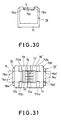
- Figs. 30 and 31 illustrates the magnetic head which is substantially similar in construction to the modification of the further embodiment described above with reference to Figs. 27, 28 and 29 and which is further provided with tape guides.
- FIG. 32, 33 and 34 A still further embodiment of a magnetic head which does not cover the present invention is illustrated in Figs. 32, 33 and 34 and is substantially similar in construction to the combination of the other and further embodiments. That is, recesses 810 and 810' are formed at the top surface of the resin 87 at which is defined the tape travel surface 82a so that the contact of the magnetic tape 5 with the resin 87 can be prevented. Moreover when the recesses 811a, 811b, 811c and 811d are formed at the top surface of the case 81 at which are defined the tape travel surfaces 82b and 82b', the side edges of the magnetic tape 5 can be prevented from making into contact with the tape travel surfaces 82b and 82b' during the traveling of the tape.
- a modification of the still further embodiment illustrated in Figs. 35, 36 and 37 is substantially similar in construction to a combination of the modification of the other and further embodiments. That is, recesses 910 and 910' are formed at the tape travel surface 92a defined over the top surface of the resin 97 and a recesses 912a, 912b, 912c and 912d are formed at the tape travel surfaces 92b and 92b' in such a way that the distance between the inner sides of the opposing recesses 912a and 912c and between the inner sides of the opposing recesses 912b and 912d is slightly narrower than the width of the magnetic tape 5.
- Figs. 38 and 39 illustrates that the magnetic tape is transported over the modified magnetic head described above with reference to Figs. 35-37.
- the production of the dust particles can be reduced to a minimum and oven when they are produced, they are almost completely prevented from adhering to the tape travel surfaces. Because of the synergetic effect obtained by the combination of the reduction in amount of the dust particles and the prevention of the dust particles to adhere to the tape travel surfaces, as compared with the other and further embodiments and their modifications, the stabilized traveling of the magnetic tape for a long period of time and the reading and writing characteristics at the magnetic gap can be satisfactorily maintained.
Landscapes
- Engineering & Computer Science (AREA)
- Manufacturing & Machinery (AREA)
- Magnetic Heads (AREA)
- Adjustment Of The Magnetic Head Position Track Following On Tapes (AREA)
Description
- The present invention relates to a magnetic head and more particularly a magnetic head for writing and reading out data into and/or from a magnetic tape in the magnetic recording apparatuses such as video tape recorders, audio tape recorders and the like.
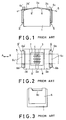
- Prior art of the magnetic head similar to the magnetic head disclosed in US-A- 4,485,420, DE-C-3518126 or EP-A- 0120518B1 is shown in Figs. 1, 2 and 3. Fig. 1 illustrates a cross sectional view, a part of which is omitted, taken along the longitudinal direction of the magnetic tape of the magnetic head; Fig. 2 is a top view thereof; and Fig. 3 is a side view thereof.
Reference numeral 1 is a case which is one of the component parts of the magnetic head and is made of a magnetic shield material. Agap 3 is formed in a portion of acore 4 which contacts with the magnetic tape. Thecore 4 is embed in thecase 1 through aresin 7.Tape guides 6 and 6' are provided with both sides of thecase 1, respectively, in the longitudinal direction of the magnetic tape. - The
magnetic tape 5 is traveling over the upper surface of the magnetic head in which data are written into and/or read out from themagnetic tape 5.Concave portions 8 and 8' are formed at a portion of the upper surface of the magnetic head to which theresin 7 is exposed to avoid themagnetic tape 5 contacting with theresin 7, so that a deboning of magnetic particles from themagnetic tape 5 can be prevented. As a result, the tape travel surfaces defined on the upper surface of the magnetic head are represented by 2a, 2b and 2b'. - It is now assumed that the magnetic tape 2 is traveling in the direction indicated by the arrow A in Fig. 2. Then the
magnetic tape 5 is made into contact with the inclined plane formed on aprojection 6b of thetape guide 6 and is biased to the reference plane formed on aprojection 6a. As best shown in Fig. 3, the width of the magnetic tape traveling passage defined between the inclined plane and the reference plane is narrower than that of themagnetic tape 5 and the tension is exerted to themagnetic tape 5. Therefore, in order to ensure the smooth traveling over the surface of the magnetic head, the positions of themagnetic tape 5 in the direction of its thickness must be limited so that abottom plane 6c is provided with between theprojection magnetic tape 5 is traveling along the reference plane. The reference planes defined on theprojections gap 3 is extended so that the position of the traveling and the longitudinal direction of themagnetic tape 5 can be stabilized. As a result, the so-called gap angle between thetape 5 and thegap 3 can be maintained constant so that the azimuth loss due to the difference in the gap angle between a writing mode and a reading mode can be reduced. - In general, the tape guides are formed by the injection molding of a plastic material which is nonexpensive, thereby reducing the production cost, but almost all the tape guides thus fabricated have the rough surfaces. As a result, due to the contact of the
magnetic tape 5 with thebottom planes tape guides 6 and 6', there occurs frequently that the magnetic material and the binder of themagnetic tape 5 are separated. - In the case of the magnetic head of the type described above, the radius of curvature of the tape travel surface defined by the
travel surfaces bottom planes tape travel surfaces bottom planes tape guides 6 and 6' and the top of thetravel surface 2a containing thegap 3. It follows therefore that themagnetic tape 5 is almost not in contact with thetape travel surfaces magnetic tape 5 separated at thebottom plane tape guides 6 and 6' are forced to reattach themagnetic tape 5 and then transported to the portion in the vicinity of thegap 3 and adhere to such the portion. As a result, such dust adversely affects a predetermined distance between thegap 3 and themagnetic tape 5 so that it becomes one of the causes which degrades the writing and reading characteristics of the magnetic head. - In general, the adhesion or accumulation of such dust tends to occur at high temperatures so that the magnetic head of the type described above cannot be used in the stereophonic audio equipment mounted on a car whose temperature becomes relatively high.
- Fig. 4, 5 and 6 illustrate another prior art of the magnetic head. Fig. 4 is a top plane view thereof; Fig. 5 is a front view thereof and Fig. 6 is a perspective view thereof. Same reference numerals are used to designate similar parts in both the magnetic heads illustrated in Figs. 4-6 and the description of the component parts already made with reference to Figs. 1-3 shall not be repeated. It should be noted here that in the second prior art of the magnetic head, the tape guides are not illustrated.
- In the second prior art of the magnetic head, the length of the
magnetic core 4 perpendicular to the longitudinal direction of themagnetic tape 5 is designed to be shorter than the width of themagnetic tape 5. For instance, while the length of themagnetic core 4 is 3.72 ± 0.05 mm, the width of themagnetic tape 5 is 3.81 - 0.05 mm to 3.81 + 0 mm so that over thesurface 2a themagnetic tape 5 and theresin 7 are made into contact with each other by the designation width of 0.09 mm. - As described above, because of the contact between the magnetic head and the magnetic tape, dust such as magnetic particles and binder particles tend to be separated from the
resin 7 so that the dust particles are transported by themagnetic tape 5 and are accumulated at thetape travel surfaces tape travel surface magnetic tape 5 so that a thin dust film is formed between themagnetic tape 5 and thetravel surface tape travel surface magnetic tape 5 at which no dust adhesion or accumulation occurs. In general, a portion of thetape travel surfaces magnetic tape 5 should be worn out uniformally, but in practice because of the nonuniform wear described above, there arises the problem that the position of the travel of themagnetic tape 5 cannot be uniformly maintained. - The
resin 7 becomes the source from which the dust particles are produced and such dust particles thus produced tend to adhere to theresin 7 compared with the tape travel surfaces. As a result, however the area of the contact between themagnetic film 5 and theresin 7 is small, for instance, when the dust particles adhere to theresin 7 in the tape travel surface, the dust particles grow from the first adhered dust particle as a nucleus. Sometimes, such growing of the dust particles prevents the smooth traveling of the magnetic tape. - In view of the above, an object of the present invention is to provide a magnetic head which can reduce the separation of dust particles from the magnetic tape so that the smooth traveling of the magnetic tape can be always ensured and therefore the degradation of the writing and reading characteristics can be prevented. This object is achieved by a magnetic head as claimed in
claim 1. - The objects effects, features and advantages of the present invention will become more apparent from the following description of embodiments thereof taken in conjunction with the accompanying drawings.
- Fig. 1 is a cross sectional view taken along the longitudinal direction of the magnetic tape illustrating a first prior art of the magnetic head;
- Fig. 2 is a top plan view thereof;
- Fig. 3 is a side view thereof;
- Fig. 4 is a top plan view of a second prior art of the magnetic head;
- Fig. 5 is a front view thereof;
- Fig. 6 is a perspective view thereof;
- Fig. 7 is a cross sectional view taken along the passage of a traveling magnetic tape illustrating a first embodiment of a magnetic head in accordance with the present invention;
- Fig. 8 is a top plan view thereof;
- Fig. 9 is a side view thereof;
- Fig. 10 is a cross sectional view taken along the passage of the traveling magnetic tape illustrating a modification of the magnetic head of the first embodiment shown in Figs. 7-9;
- Fig. 11 is a top plan view thereof;
- Fig. 12 is a side view thereof;
- Fig. 13 is a cross sectional view taken along the passage of the traveling magnetic tape illustrating a second embodiment of a magnetic head in accordance with the present invention;
- Fig. 14 is a top plan view thereof;
- Fig. 15 is a side view thereof;
- Fig. 16 is a cross sectional view, taken along the passage of the traveling magnetic tape illustrating a modification of the magnetic head of the second embodiment shown in Figs. 13-15;
- Fig. 17 is a top plan view thereof;
- Fig. 18 is a side view thereof;
- Fig. 19 is a top plan view of a third embodiment of a magnetic head in accordance with the present invention;
- Fig. 20 is a front view thereof;
- Fig. 21 is a perspective view thereof;
- Fig. 22 is a side view illustrating the magnetic head shown in Fig. 19 having tape guides;
- Fig. 23 is a top plan view of the magnetic head shown in Fig. 22;
- Fig. 24 is a top plan view of a fourth embodiment of a magnetic head in accordance with the present invention;
- Fig. 25 is a front view thereof;
- Fig. 26 is a perspective view thereof;
- Fig. 27 is a top plan view illustrating a modification of the magnetic head of the fourth embodiment shown in Figs. 24-26;
- Fig. 28 is a front view thereof;
- Fig. 29 is a perspective view thereof;
- Fig. 30 is a side view illustrating the magnetic head shown in Fig. 27 having tape guides;
- Fig. 31 is a top plan view thereof;
- Fig. 32 is a top plan view illustrating a fifth embodiment of a magnetic head in accordance with the present invention;
- Fig. 33 is a front view thereof;
- Fig. 34 is a perspective view thereof;
- Fig. 35 is a top plan view illustrating a modification of the magnetic head of the fifth embodiment shown in Figs. 32-34;
- Fig. 36 is a front view thereof;
- Fig. 37 is a perspective view thereof;
- Fig. 38 is a side view illustrating the magnetic head shown in Fig. 25 having tape guides; and
- Fig. 39 is a top plan view thereof.
- In the following embodiments and their modifications, like reference numerals prefixed with the various number represent corresponding parts in the several views. For instance, the case designated by the
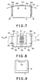
reference numeral 1 in Figs. 1-6 is changed to 11. These component parts have been already described in detail so that the component part corresponding to those in Figs. 1-6 shall not be described hereinafter except when their explanation is especially needed. - In the preliminary embodiment, which does not cover the present invention, shown in Figs. 7-9, the radius of curvature of the
type 12b and 12b' is made greater than those of the tape travel surfaces of the prior art of the magnetic heads described above. More particularly, when the radius of curvature of the tape travel surfaces in the prior art of the magnetic heads is between 10 and 15 mm, in the first embodiment, the corresponding radius of curvature is of the order of 20 mm. In this case, the radius of curvature of the curved surface interconnecting thetravel surfaces 12atape travel surfaces bottom plane - When it is assumed that the
magnetic tape 5 is traveling in the direction indicated by the arrow A in Fig. 8, because of the increase in radius of curvature of the curved surface interconnecting thetape travel surface bottom plane 16c and thetape travel surface 12b, thebottom plane 16c' and thetape travel surface 12b' being substantially aligned with each other, first themagnetic tape 5 is made into contact with the bottom 16c of thetape guide 16 so that the direction and position of the traveling magnetic tape can be correctly controlled. Thereafter themagnetic tape 5 is made into contact with almost all thetape travel surface 12b. Then the dust particles produced at thebottom plane 16c are reattached to themagnetic tape 5 and almost all of them attach or adhere to thetape travel surface 12b. Therefore, there exists almost no chance that the dust particles reach thetape travel surface 12a through which themagnetic gap 13 is defined. As a result, even when the magnetic head is used for a long time under the high temperature condition, the writing and reading characteristics can be prevented from being degraded due to the adhesion or accumulation of the dust in the vicinity of the magnetic gap. - The travel surfaces 12b and 12b' are integrally formed with the
case 11 made of a magnetic shielding material. This material, metal, is ground by a grinder or the like until the surfaces become so smooth that the roughness of surface becomes in excess of 0.1 S. It follows therefore that at the travel surfaces 12b and 12b', the rate of production of dust such as magnetic particles and binder particles separated from themagnetic tape 5 is very low, and the rate of the adhesion or accumulation of dust is higher than that at the bottom surfaces 16 and 16c' of the tap guides 16 and 16', respectively. - Same is true when the
magnetic tape 5 is traveling in the direction indicated by the arrow B in Fig. 8. That is, the dust particles produced at thebottom surface 16c' of the tap guide 16' almost attach or adhere to thetape travel surface 12b' so that the degradation of the magnetic characteristics due to the adhesion or accumulation of the dust particles in the vicinity of the magnetic gap can be prevented. - In order to slightly extend upwardly the bottom surfaces 16c and 16c' of the
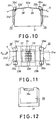
tape guide 16 beyond the tape travel surfaces, the precise position adjustment is required. Otherwise the above-described merit cannot be satisfactorily attained. On the other hand, in accordance with the preliminary embodiment, as best shown in Figs. 7 and 8, theprojections tape guide 16 are made into contact with thetape travel surface 12b on the side of the tape guide in assembly so that the position of theposition control plane 16c relative to thetape travel surface 12b can be correctly determined. In the same manner, theprojections 16a' and 16b' of the tape guide 16' can be made into contact with thetape travel surface 12b' on the side of the tape guide in assembly, the position of theposition control plane 16c' relative to thetape travel surface 12b' can be correctly determined. - In the case of a modification of the preliminary embodiment illustrated in Figs. 10, 11 and 12, the radius of curvature of the tape travel surfaces and the positions of the
bottom plane tape guide 26 are determined in a manner substantially similar to that described above in the preliminary embodiment. In addition, as best shown in Figs. 10 and 11, the upper portion of thecase 11 is formed withcutout portions magnetic tape 5 and the position control planes 26c and 26c' of the tape guides 26 and 26' are extended to the cutout portions ornotches - When the length of the
position control plane magnetic tape 5 on the other hand can be lowered so that the resistance to wear of the position control planes 26c and 26c' can be improved. - In the preliminary embodiment and its modification, the positions of the bottom planes relative to the tape travel surfaces and the radius of curvature of the tape travel surfaces are suitably determined as described above so that the magnetic tape is forced to make into contact with the inclined planes and the bottom planes of the tape guides and is forcibly biased satisfactorily toward the reference planes of the other projection, whereby the position and direction of the traveling tape can be stabilized.
- Furthermore, in the case of the preliminary embodiment and its modification, the dust particles produced at the bottom planes of the tape guides are forced to adhere to the tape travel surfaces on the side of the tape guides due to the suitable selection of the above-mentioned radius of curvature. Thus the dust particles almost uniformly adhere so that the position and the direction of the traveling tape will not be adversely affected.
- Next referring to Figs. 13, 14 and 15, the embodiment of a magnetic head in accordance with the present invention will be described.
Recesses projections recesses projections magnetic gap 33 in the longitudinal direction of the tape, respectively. In the embodiment, the reference planes and inclined planes of the projections intersect the tape travel surfaces 36b and 32b' through therecesses - When the length of the magnetic head along the longitudinal direction of the tape is determined 11.4 mm and the quantity of the projection of the magnetic head is 1.8 mm in the embodiment, the overall tape travel surface interconnecting the
tape travel surfaces magnetic tape 5, which is, traveling, initially makes into contact with thetape travel surface tape travel surface projection projections 36a' and 36b'. - Next when the
magnetic tape 5 is traveling in the direction indicated by the arrow A in Fig. 14, the magnetic tape initially makes contact with thetape travel surface 32b on the side of the tape guide. Under this condition, a portion of thetape travel surface 32b which is made into contact with themagnetic tape 5 is located between the inclined plane of theprojection 36b and the reference plane of theprojection 36a. As a result, the travel direction and the travel position can be correctly controlled by the inclined plane of theprojection 36b and the reference plane of theprojection 36a. - As best shown in Fig. 13, the
bottom plane magnetic tape 5 so that the dust particles due to the contact between themagnetic tape 5 and the bottom planes 36c and 36c' can be prevented from being produced. Furthermore, thetape travel surface 32b are defined over the top surface of thecase 31 as in the case of the preliminary embodiment and its modification described above and thecase 31 is made of a metal. In addition, the surfaces of thecase 31 are finished very smoothly. As a result, the production of the dust particles such as magnetic particles and binder particles at thetape travel surface 32b can be substantially eliminated so that unlike the conventional magnetic heads, no dust is accumulated or adhered to the surface in the vicinity of themagnetic gap 33. - Same is true for the case in which the
magnetic tape 5 is traveling in the direction indicated by the arrow B in Fig. 14 so that there is no fear that the production of the dust particles such as magnetic particles and binder particles resulting from the traveling of the magnetic tape occurs. - Next referring to Figs. 16, 17 and 18, a modification of the embodiment of a magnetic head in accordance with the present invention will be described in detail hereinafter. Unlike the embodiment described above, the modification of the embodiment is not especially formed with the recesses at both the side edges of the tape travel surface, but the radius of curvature of the overall tape travel surface is determined in a manner similar to the described above with reference to Figs. 13-15 (the embodiment). The positions of the
bottom plane magnetic tape 5 while themagnetic tape 5 initially makes in contact with thetape travel surface case 41. As a result, the profile lines on the sides of the guides of the tape travel surfaces 42b and 42b' are located very close to the reference planes defined by theprojections projections magnetic tape 5, the tape travel surfaces 42b and 42b' on the side of the tape guide becomes continuous with the reference planes defined by theprojection projections magnetic tape 5 can be correctly controlled. - When the tape travel surfaces 42b and 42b' on the sides of the tape guides are continuous with or merge with the reference planes defined by the
projections projections magnetic tape 5 can be correctly controlled. - When the tape travel surfaces 42b and 42b' on the sides of the tape guides, respectively, merge with the reference planes defined by the
projections projections case 41 on the other hand are taken into consideration, but the discontinuity among them may be tolerated as long as the effects described above is not reduced. - Referring next to the Figs. 19, 20 and 21, another embodiment of a magnetic head which does not cover the present invention will be described. First the other embodiment is formed with
grooves 510 and 510' at thetape travel surface 52a defined by theresin 57 so that the contact of themagnetic tape 5 and theresin 57 is avoided. - These
grooves 510 and 510' will be described in detail below. The distance between the inner side surfaces of thegrooves 510 and 510' is made smaller than the width of the magnetic core 54 (which is 3.72 ± 0.05 mm) and furthermore noresin 57 remains at the end faces of thecore 54 along the boundary between the core 54 and theresin 57. - The width of the
grooves 510 and 510' is of the order of 0.2 mm and the size of thegrooves 510 and 510' is so determined that both of the side edges of themagnetic tape 5 may be located within therecesses 510 and 510' and is preferably reduced as small as possible so that the contact of the sides edges of themagnetic tape 5 will not make contact with theresin 57 located outwardly of the recesses orgrooves 510 and 510'. When the width of therecesses 510 and 510' is determined in excess of 1 mm, a portion of a pad (not shown) which presses against thetape travel surface 52a from the upper side of the core 54 falls into therecesses 510 and 510' so that themagnetic tape 5 is bent within therecesses 510 and 510'. As a result, there occur various problems that the writing and reading characteristics are degraded due to the failure of the correct determination of the azimuth and that the side edges of themagnetic tape 5 are twisted, causing the damage to themagnetic tape 5. - The depth of the
recesses 510 and 510' is so determined that a shorter length of the side edges of themagnetic tape 5 remain within therecesses 510 and 510', for instance, even when themagnetic tape 55 is pressed by the pad (of the type described above), it will not be made in contact with the bottoms of therecesses 510 and 510'. - With the magnetic head with the above-described construction, the contact of the
magnetic tape 5 with some portions of theresin 57 located on both sides of themagnetic core 54 can be prevented so that the separation and adhesion of the dust particles at these portions can be avoided. - When the other embodiment is provided with the tape guides 56 and 56' as shown in Figs. 22 and 23, more advantageous effects can be attained.
- Figs. 22 and 23 illustrate the other embodiment provided with tape guides 56 and 56'. First, the function of the tape guides 56 and 56' will be described. The
magnetic tape 5 is pressed against thebottom plane 56c of thetape guide 56 under the tension of themagnetic tape 5, and is made into contact with the inclined plane defined by theprojection 56b of thetape guide 56 and is biased toward the reference plane defined by theprojection 56a of thetape guide 56. The reference plane is substantially perpendicular to thebottom plane 56c so that one side edges of themagnetic tape 5 is traveling along the reference surface. In this case, the reference plane is defined to the substantially perpendicular to themagnetic gap 53 so that the position and direction of the traveling tape can be maintained always in the stabilized conditions. The angle defined by themagnetic tape 5 and themagnetic gap 53 is also maintained in the stabilized condition so that the azimuth loss resulting from the difference in gap angle between the data writing mode and the data readout mode can be reduced to a minimum. - As described above, the tape guides 56 and 56' are in general formed by the injection molding of a resin which is inexpensive, but their surfaces are almost rough. Therefore when the
magnetic tape 5 is pressed against the reference planes defined by theprojections magnetic tape 5 tends to occur frequently. As a result, in the case of the conventional magnetic head of the type described above, the dust particles produced from the side edges of themagnetic tape 5 adhere to the resin over thetape travel surface 52a in many cases, but the other embodiment is remarkably effective to prevent satisfactorily the dust particles from adhering the resin. More particularly, since the recesses are formed in some resin located on both sides of the core, the position and direction of the traveling tape in the modification of the other embodiment described above can be maintained in the stabilized state. - Next referring to Figs. 24, 25 and 26, a further embodiment of a magnetic head which does not cover the present invention will be described. In the further embodiment, grooves or
elongated recesses head case 61 at which are defined the tape travel surfaces 62b and 62b' so that the contact of both side edges of themagnetic tape 5 with the tape travel surfaces 62b and 62b' is prevented. - The function of the
recesses recesses recesses magnetic tape 5 with theresin 67 and adhered to the sides edges of thetape 5 are carried to thetape travel surface - As described in the other embodiment, the depth of the
recesses magnetic tape 5 will not be made into contact with the bottom of these recesses. - With the magnetic head of the type described above, the dust particles adhered to the side edges of the
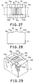
tape 5 can be prevented to adhere to thetape travel surface head case 61 can be prevented. - Referring now to Figs. 27, 28 and 29, a modification of the further embodiment of a magnetic head which does not cover the present invention will be described. According to the further embodiment, recesses 712a, 712b, 172c and 712d in such a manner that the inner distance between the opposing
recesses recesses magnetic tape 5 are formed over a portion of the tape travel surface of thehead case 71 at which the tape travel surfaces 72b and 72b' are defined . Thus the contact of the side edges of themagnetic tape 5 with the tape travel surfaces 72b and 72b' can be prevented. - Therefore, like the further embodiment shown in Figs. 24, 25 and 26 the magnetic head modified in the manner described above can be used for a long time at high temperature without causing any adverse effects to the traveling of the
magnetic tape 5. - Moreover when the magnetic head of the further embodiment and its modification is provided with tape guides as will be described below with reference to Figs. 30 and 31, it can attain more remarkable effects.
- Figs. 30 and 31 illustrates the magnetic head which is substantially similar in construction to the modification of the further embodiment described above with reference to Figs. 27, 28 and 29 and which is further provided with tape guides.
- As described above with reference to Figs. 22 and 23, because of the formation of the
recesses tape travel surface - In the case of the further embodiment and its modification described above, when the longitudinal direction of the tape is always maintained in a predetermined direction, it is apparent to those skilled in the art that they may be formed at the downstream side of the direction of the traveling tape.
- A still further embodiment of a magnetic head which does not cover the present invention is illustrated in Figs. 32, 33 and 34 and is substantially similar in construction to the combination of the other and further embodiments. That is, recesses 810 and 810' are formed at the top surface of the
resin 87 at which is defined thetape travel surface 82a so that the contact of themagnetic tape 5 with theresin 87 can be prevented. Moreover when therecesses case 81 at which are defined the tape travel surfaces 82b and 82b', the side edges of themagnetic tape 5 can be prevented from making into contact with the tape travel surfaces 82b and 82b' during the traveling of the tape. - A modification of the still further embodiment illustrated in Figs. 35, 36 and 37 is substantially similar in construction to a combination of the modification of the other and further embodiments. That is, recesses 910 and 910' are formed at the
tape travel surface 92a defined over the top surface of theresin 97 and arecesses recesses recesses magnetic tape 5. - Figs. 38 and 39 illustrates that the magnetic tape is transported over the modified magnetic head described above with reference to Figs. 35-37.
- In the cases of the still further embodiment and its modification with or without the tape guides, the production of the dust particles can be reduced to a minimum and oven when they are produced, they are almost completely prevented from adhering to the tape travel surfaces. Because of the synergetic effect obtained by the combination of the reduction in amount of the dust particles and the prevention of the dust particles to adhere to the tape travel surfaces, as compared with the other and further embodiments and their modifications, the stabilized traveling of the magnetic tape for a long period of time and the reading and writing characteristics at the magnetic gap can be satisfactorily maintained.
Claims (3)
- A magnetic head for writing and/or reading data into and/or from a magnetic tape (5), comprising:a) a magnetic core (34; 44);b) a case member (31; 41) for holding said magnetic core; andc) a tape guide (36, 36'; 46, 46') having a reference surface which determines a position of an edge of said magnetic tape and an inclined surface which is disposed opposite to said reference surface for urging said magnetic tape to said reference surface, said reference surface and said inclined surface being provided on respective projections (36a,b, 36a',b'; 46a,b, 46a',b') of said tape guide, said tape guide further having a bottom surface (36c,c'; 46c,c') which is located between said respective projections; andd) a tape slide surface (32) on which said magnetic tape slides in contact therewith,
said magnetic head being characterized in thate) said bottom surface of said tape guide is lowered with respect to said tape slide surface such that it does not interfere the traveling of said magnetic tape. - A magnetic head according to claim 1,
characterized by recesses (39a, 39a', 39b, 39b') formed into a section of saic tape slide surface (32) arranged between said reference surface and said inclined surface at the edges of said case member (31) in order to enable an intersection of said reference and said inclined surface with the tape travel surface plane within said recesses (39a, 39a', 39b, 39b'). - A magnetic head according to claim 2,
characterized in that said section is arranged between a top of said inclined surface and a bottom thereof in a direction of thickness of said magnetic tape (5).
Applications Claiming Priority (10)
| Application Number | Priority Date | Filing Date | Title |
|---|---|---|---|
| JP48916/89 | 1989-02-28 | ||
| JP1048917A JPH02227858A (en) | 1989-02-28 | 1989-02-28 | Magnetic head device |
| JP48917/89 | 1989-02-28 | ||
| JP1048916A JPH02227857A (en) | 1989-02-28 | 1989-02-28 | Magnetic head device |
| JP126385/89 | 1989-05-19 | ||
| JP12638489A JPH02306405A (en) | 1989-05-19 | 1989-05-19 | Magnetic head |
| JP12638689A JPH02306407A (en) | 1989-05-19 | 1989-05-19 | Magnetic head |
| JP126384/89 | 1989-05-19 | ||
| JP126386/89 | 1989-05-19 | ||
| JP12638589A JPH02306406A (en) | 1989-05-19 | 1989-05-19 | Magnetic head |
Publications (3)
| Publication Number | Publication Date |
|---|---|
| EP0385359A2 EP0385359A2 (en) | 1990-09-05 |
| EP0385359A3 EP0385359A3 (en) | 1992-04-15 |
| EP0385359B1 true EP0385359B1 (en) | 1996-01-10 |
Family
ID=27522754
Family Applications (1)
| Application Number | Title | Priority Date | Filing Date |
|---|---|---|---|
| EP90103718A Expired - Lifetime EP0385359B1 (en) | 1989-02-28 | 1990-02-26 | Magnetic head |
Country Status (3)
| Country | Link |
|---|---|
| US (1) | US5574606A (en) |
| EP (1) | EP0385359B1 (en) |
| DE (1) | DE69024676T2 (en) |
Families Citing this family (15)
| Publication number | Priority date | Publication date | Assignee | Title |
|---|---|---|---|---|
| US5982592A (en) * | 1995-11-20 | 1999-11-09 | Sony Corporation | Magnetic tape stabilizer for a recording and playback device |
| JP2928168B2 (en) * | 1996-08-28 | 1999-08-03 | ティーディーケイ株式会社 | Thin film magnetic head |
| US5831792A (en) * | 1997-04-11 | 1998-11-03 | Western Digital Corporation | Slider having a debris barrier surrounding a transducer |
| JP3237751B2 (en) * | 1997-04-11 | 2001-12-10 | ティーディーケイ株式会社 | Magnetic head |
| US5883770A (en) * | 1997-07-18 | 1999-03-16 | International Business Machines Corporation | Partial width mass produced linear tape recording head |
| US6587305B2 (en) * | 2001-03-28 | 2003-07-01 | Quantum Corporation | Tape head with transducer supports having raised, wear-resistant surfaces at edges of softer core |
| JP2004342211A (en) * | 2003-05-15 | 2004-12-02 | Fuji Photo Film Co Ltd | Magnetic head assembly and servo writer |
| US6937435B2 (en) * | 2003-05-16 | 2005-08-30 | Quantum Corporation | Tape head with thin support surface and method of manufacture |
| US7154691B2 (en) * | 2003-12-18 | 2006-12-26 | Quantum Corporation | Multi-format thinfilm head and associated methods |
| US7271983B2 (en) * | 2004-09-16 | 2007-09-18 | Quantum Corporation | Magnetic head with mini-outriggers and method of manufacture |
| US7256963B2 (en) * | 2004-09-16 | 2007-08-14 | Quantum Corporation | Magnetic head with adaptive data island and mini-outrigger and methods of manufacture |
| US20070183091A1 (en) * | 2006-02-03 | 2007-08-09 | Saliba George A | Read/write head having varying wear regions and methods of manufacture |
| US20100196739A1 (en) * | 2009-02-05 | 2010-08-05 | Tdk Corporation | Magnetic head, manufacturing method therefor and magnetic tape device |
| US9214164B2 (en) * | 2013-09-16 | 2015-12-15 | International Business Machines Corporation | Miniskirt tape head having quasi-statically tilted transducer arrays |
| US9984720B1 (en) | 2017-01-10 | 2018-05-29 | International Business Machines Corporation | Damping lateral tape motion disturbances |
Family Cites Families (35)
| Publication number | Priority date | Publication date | Assignee | Title |
|---|---|---|---|---|
| DK104262C (en) * | 1962-12-10 | 1966-04-25 | Bang & Olufsen Produktionssels | Tone head for tape recorders. |
| US3435442A (en) * | 1965-03-26 | 1969-03-25 | Ampex | Fluid lubricated magnetic tape transducer |
| US3643037A (en) * | 1969-04-14 | 1972-02-15 | Ibm | Separation control for record media transducer with transverse slots to supply ambient pressure |
| SU415708A1 (en) * | 1971-09-13 | 1974-02-15 | ||
| JPS5320917A (en) * | 1976-08-11 | 1978-02-25 | Hitachi Ltd | Multielement magnetic head |
| SU595775A1 (en) * | 1976-10-04 | 1978-02-28 | Предприятие П/Я А-3593 | Magnetic head |
| JPS5449104A (en) * | 1977-09-27 | 1979-04-18 | Nec Corp | Magnetic head and magnetic tape apparatus |
| JPS55117728A (en) * | 1979-03-06 | 1980-09-10 | Victor Co Of Japan Ltd | Magnetic head |
| NL8200175A (en) * | 1981-04-13 | 1982-11-01 | Philips Nv | MAGNETIC BAND TAPE DEVICE AND MAGNETIC UNIT APPLICABLE TO SUCH A DEVICE. |
| JPS57200922A (en) * | 1981-06-03 | 1982-12-09 | Mitsubishi Electric Corp | Multitrack magnetic head |
| JPS5880122A (en) * | 1981-11-04 | 1983-05-14 | Canon Electronics Inc | Magnetic head |
| JPS5888824A (en) * | 1981-11-24 | 1983-05-27 | Nec Corp | Magnetic tape device |
| JPS5888825A (en) * | 1981-11-24 | 1983-05-27 | Nec Corp | Magnetic head |
| JPS593718A (en) * | 1982-06-30 | 1984-01-10 | Toshiba Corp | Magnetic head |
| NL8300730A (en) * | 1983-02-28 | 1984-09-17 | Philips Nv | MAGNETIC BAND TAPE DEVICE AND MAGNET HEAD UNIT APPLICABLE TO SUCH APPARATUS. |
| JPS60191403A (en) * | 1984-03-12 | 1985-09-28 | Canon Electronics Inc | Magnetic head |
| JPS60223013A (en) * | 1984-04-20 | 1985-11-07 | Canon Electronics Inc | Magnetic head |
| JPS6148110A (en) * | 1984-08-16 | 1986-03-08 | Canon Electronics Inc | Magnetic head |
| JPS61216103A (en) * | 1984-08-24 | 1986-09-25 | Canon Electronics Inc | Magnetic head |
| JPS6154011A (en) * | 1984-08-24 | 1986-03-18 | Canon Electronics Inc | Magnetic head |
| JPS61187150A (en) * | 1985-02-15 | 1986-08-20 | Akai Electric Co Ltd | Reverse type tape running device |
| JPS61214109A (en) * | 1985-03-20 | 1986-09-24 | Hitachi Maxell Ltd | Magnetic head and its manufacture |
| DE3518126C1 (en) * | 1985-05-21 | 1986-07-31 | Philips Patentverwaltung Gmbh, 2000 Hamburg | Magnetic head unit for a magnetic tape device with a plastic holder |
| JPH0778855B2 (en) * | 1985-09-05 | 1995-08-23 | キヤノン株式会社 | Magnetic head |
| JPS62117112A (en) * | 1985-11-18 | 1987-05-28 | Teac Co | Magnetic head |
| JPH0727615B2 (en) * | 1986-11-25 | 1995-03-29 | キャノン電子株式会社 | Magnetic head |
| US4894737A (en) * | 1986-12-05 | 1990-01-16 | Canon Kabushiki Kaisha | Magnetic head apparatus having projections extending from at least a front side thereof |
| JP2802620B2 (en) * | 1987-07-31 | 1998-09-24 | キヤノン電子 株式会社 | Magnetic head |
| US4888657A (en) * | 1987-12-28 | 1989-12-19 | Eastman Kodak Company | Contoured head assembly for use in a cassette loaded recorder |
| SU1527661A1 (en) * | 1988-03-21 | 1989-12-07 | Предприятие П/Я А-3593 | Magnetic head for measuring signalograms |
| DE3812362A1 (en) * | 1988-04-14 | 1989-10-26 | Philips Patentverwaltung | MAGNETIC TAPE CASSETTE DEVICE WITH A HEAD PLATE AND A MAGNETIC HEAD UNIT FOR THIS MAGNETIC TAPE CASSETTE DEVICE |
| JP2761214B2 (en) * | 1988-06-17 | 1998-06-04 | キヤノン電子株式会社 | Magnetic head device |
| JP2678019B2 (en) * | 1988-07-08 | 1997-11-17 | シャープ株式会社 | Magnetic recording / reproducing device |
| US4956737A (en) * | 1989-04-04 | 1990-09-11 | Eastman Kodak Company | Magnetic head contour utilizing facets for air film skiving |
| US5124866A (en) * | 1990-02-01 | 1992-06-23 | Minnesota Mining And Manufacturing Company | Recording head core yoke with full length core support |
-
1990
- 1990-02-26 EP EP90103718A patent/EP0385359B1/en not_active Expired - Lifetime
- 1990-02-26 DE DE69024676T patent/DE69024676T2/en not_active Expired - Fee Related
-
1995
- 1995-04-14 US US08/422,651 patent/US5574606A/en not_active Expired - Fee Related
Also Published As
| Publication number | Publication date |
|---|---|
| EP0385359A2 (en) | 1990-09-05 |
| US5574606A (en) | 1996-11-12 |
| DE69024676T2 (en) | 1996-05-30 |
| DE69024676D1 (en) | 1996-02-22 |
| EP0385359A3 (en) | 1992-04-15 |
Similar Documents
| Publication | Publication Date | Title |
|---|---|---|
| US5574606A (en) | Magnetic head having dust handling tape slide surface | |
| KR100270281B1 (en) | Bidirectional flat contour linear tape recording head and drive | |
| US4888657A (en) | Contoured head assembly for use in a cassette loaded recorder | |
| US5430591A (en) | Negative pressure flying head slider having siderails with narrow width portion | |
| US5426551A (en) | Magnetic contact head having a composite wear surface | |
| CA1094220A (en) | Magnetic tape casssette | |
| JPH08203166A (en) | Magnetic head device | |
| US5781383A (en) | Magnetic head for stable tip to tape contact pressure despite head wear and tape tension variation | |
| US5091810A (en) | Floating type magnetic head having head core affixed to outside surface of slider | |
| EP0397713B1 (en) | Contoured head assembly for use in a cassette loaded recorder | |
| US6359753B1 (en) | Floating magnetic head for use with flexible disks | |
| US4602307A (en) | Compound type magnetic head | |
| JP2803659B2 (en) | Magnetic head slider | |
| US5644449A (en) | Magnetic head slider assembly | |
| EP0176131A1 (en) | Magnetic head | |
| US4237505A (en) | Combined recording and playback magnetic tape head with shield cases and a flat chip for controlling tape wrap angle | |
| JPH02306406A (en) | Magnetic head | |
| JPH02306405A (en) | Magnetic head | |
| JPH02227858A (en) | Magnetic head device | |
| US5528441A (en) | Magnetic head including track edges having a cut-end face | |
| JPH02306407A (en) | Magnetic head | |
| US4263633A (en) | Combined magnetic tape head | |
| JP2000155905A (en) | Multitrack magnetic head | |
| JP3017001B2 (en) | Magnetic head | |
| US5949626A (en) | Magnetic head having a C-type core and an I-type core |
Legal Events
| Date | Code | Title | Description |
|---|---|---|---|
| PUAI | Public reference made under article 153(3) epc to a published international application that has entered the european phase |
Free format text: ORIGINAL CODE: 0009012 |
|
| AK | Designated contracting states |
Kind code of ref document: A2 Designated state(s): DE FR GB NL |
|
| 17P | Request for examination filed |
Effective date: 19901016 |
|
| PUAL | Search report despatched |
Free format text: ORIGINAL CODE: 0009013 |
|
| AK | Designated contracting states |
Kind code of ref document: A3 Designated state(s): DE FR GB NL |
|
| 17Q | First examination report despatched |
Effective date: 19931203 |
|
| GRAA | (expected) grant |
Free format text: ORIGINAL CODE: 0009210 |
|
| AK | Designated contracting states |
Kind code of ref document: B1 Designated state(s): DE FR GB NL |
|
| REF | Corresponds to: |
Ref document number: 69024676 Country of ref document: DE Date of ref document: 19960222 |
|
| ET | Fr: translation filed | ||
| PLBE | No opposition filed within time limit |
Free format text: ORIGINAL CODE: 0009261 |
|
| STAA | Information on the status of an ep patent application or granted ep patent |
Free format text: STATUS: NO OPPOSITION FILED WITHIN TIME LIMIT |
|
| 26N | No opposition filed | ||
| REG | Reference to a national code |
Ref country code: GB Ref legal event code: IF02 |
|
| PGFP | Annual fee paid to national office [announced via postgrant information from national office to epo] |
Ref country code: FR Payment date: 20020212 Year of fee payment: 13 |
|
| PGFP | Annual fee paid to national office [announced via postgrant information from national office to epo] |
Ref country code: GB Payment date: 20020227 Year of fee payment: 13 |
|
| PGFP | Annual fee paid to national office [announced via postgrant information from national office to epo] |
Ref country code: NL Payment date: 20020228 Year of fee payment: 13 |
|
| PGFP | Annual fee paid to national office [announced via postgrant information from national office to epo] |
Ref country code: DE Payment date: 20020314 Year of fee payment: 13 |
|
| PG25 | Lapsed in a contracting state [announced via postgrant information from national office to epo] |
Ref country code: GB Free format text: LAPSE BECAUSE OF NON-PAYMENT OF DUE FEES Effective date: 20030226 |
|
| PG25 | Lapsed in a contracting state [announced via postgrant information from national office to epo] |
Ref country code: NL Free format text: LAPSE BECAUSE OF NON-PAYMENT OF DUE FEES Effective date: 20030901 |
|
| PG25 | Lapsed in a contracting state [announced via postgrant information from national office to epo] |
Ref country code: DE Free format text: LAPSE BECAUSE OF NON-PAYMENT OF DUE FEES Effective date: 20030902 |
|
| GBPC | Gb: european patent ceased through non-payment of renewal fee | ||
| PG25 | Lapsed in a contracting state [announced via postgrant information from national office to epo] |
Ref country code: FR Free format text: LAPSE BECAUSE OF NON-PAYMENT OF DUE FEES Effective date: 20031031 |
|
| NLV4 | Nl: lapsed or anulled due to non-payment of the annual fee |
Effective date: 20030901 |
|
| REG | Reference to a national code |
Ref country code: FR Ref legal event code: ST |