EP0384346A1 - Unterbrechungsvorrichtung für Hochspannungsgleichstrom - Google Patents
Unterbrechungsvorrichtung für Hochspannungsgleichstrom Download PDFInfo
- Publication number
- EP0384346A1 EP0384346A1 EP90103134A EP90103134A EP0384346A1 EP 0384346 A1 EP0384346 A1 EP 0384346A1 EP 90103134 A EP90103134 A EP 90103134A EP 90103134 A EP90103134 A EP 90103134A EP 0384346 A1 EP0384346 A1 EP 0384346A1
- Authority
- EP
- European Patent Office
- Prior art keywords
- windings
- superconductive
- current
- cryostat
- capacitor
- Prior art date
- Legal status (The legal status is an assumption and is not a legal conclusion. Google has not performed a legal analysis and makes no representation as to the accuracy of the status listed.)
- Withdrawn
Links
- 238000004804 winding Methods 0.000 claims abstract description 62
- 239000003990 capacitor Substances 0.000 claims abstract description 21
- 230000007704 transition Effects 0.000 claims description 16
- 238000010438 heat treatment Methods 0.000 claims description 3
- 230000000694 effects Effects 0.000 claims description 2
- 239000002887 superconductor Substances 0.000 claims 1
- 239000004020 conductor Substances 0.000 description 5
- 239000007788 liquid Substances 0.000 description 4
- 239000012530 fluid Substances 0.000 description 3
- 238000012546 transfer Methods 0.000 description 3
- 238000007796 conventional method Methods 0.000 description 2
- 238000010586 diagram Methods 0.000 description 2
- 238000011144 upstream manufacturing Methods 0.000 description 2
- RYGMFSIKBFXOCR-UHFFFAOYSA-N Copper Chemical compound [Cu] RYGMFSIKBFXOCR-UHFFFAOYSA-N 0.000 description 1
- 229910001275 Niobium-titanium Inorganic materials 0.000 description 1
- 230000001174 ascending effect Effects 0.000 description 1
- 239000010949 copper Substances 0.000 description 1
- 229910052802 copper Inorganic materials 0.000 description 1
- 238000001514 detection method Methods 0.000 description 1
- 238000011161 development Methods 0.000 description 1
- 229910052734 helium Inorganic materials 0.000 description 1
- 239000001307 helium Substances 0.000 description 1
- SWQJXJOGLNCZEY-UHFFFAOYSA-N helium atom Chemical compound [He] SWQJXJOGLNCZEY-UHFFFAOYSA-N 0.000 description 1
- 239000000463 material Substances 0.000 description 1
- 238000000034 method Methods 0.000 description 1
- RJSRQTFBFAJJIL-UHFFFAOYSA-N niobium titanium Chemical compound [Ti].[Nb] RJSRQTFBFAJJIL-UHFFFAOYSA-N 0.000 description 1
- 238000013021 overheating Methods 0.000 description 1
- 239000007787 solid Substances 0.000 description 1
- 230000001052 transient effect Effects 0.000 description 1
Images
Classifications
-
- H—ELECTRICITY
- H02—GENERATION; CONVERSION OR DISTRIBUTION OF ELECTRIC POWER
- H02H—EMERGENCY PROTECTIVE CIRCUIT ARRANGEMENTS
- H02H9/00—Emergency protective circuit arrangements for limiting excess current or voltage without disconnection
- H02H9/02—Emergency protective circuit arrangements for limiting excess current or voltage without disconnection responsive to excess current
- H02H9/023—Current limitation using superconducting elements
-
- H—ELECTRICITY
- H01—ELECTRIC ELEMENTS
- H01H—ELECTRIC SWITCHES; RELAYS; SELECTORS; EMERGENCY PROTECTIVE DEVICES
- H01H33/00—High-tension or heavy-current switches with arc-extinguishing or arc-preventing means
- H01H33/02—Details
- H01H33/04—Means for extinguishing or preventing arc between current-carrying parts
- H01H33/16—Impedances connected with contacts
-
- H—ELECTRICITY
- H01—ELECTRIC ELEMENTS
- H01F—MAGNETS; INDUCTANCES; TRANSFORMERS; SELECTION OF MATERIALS FOR THEIR MAGNETIC PROPERTIES
- H01F6/00—Superconducting magnets; Superconducting coils
- H01F2006/001—Constructive details of inductive current limiters
-
- H—ELECTRICITY
- H01—ELECTRIC ELEMENTS
- H01H—ELECTRIC SWITCHES; RELAYS; SELECTORS; EMERGENCY PROTECTIVE DEVICES
- H01H33/00—High-tension or heavy-current switches with arc-extinguishing or arc-preventing means
- H01H33/02—Details
- H01H33/59—Circuit arrangements not adapted to a particular application of the switch and not otherwise provided for, e.g. for ensuring operation of the switch at a predetermined point in the ac cycle
- H01H33/596—Circuit arrangements not adapted to a particular application of the switch and not otherwise provided for, e.g. for ensuring operation of the switch at a predetermined point in the ac cycle for interrupting dc
-
- Y—GENERAL TAGGING OF NEW TECHNOLOGICAL DEVELOPMENTS; GENERAL TAGGING OF CROSS-SECTIONAL TECHNOLOGIES SPANNING OVER SEVERAL SECTIONS OF THE IPC; TECHNICAL SUBJECTS COVERED BY FORMER USPC CROSS-REFERENCE ART COLLECTIONS [XRACs] AND DIGESTS
- Y02—TECHNOLOGIES OR APPLICATIONS FOR MITIGATION OR ADAPTATION AGAINST CLIMATE CHANGE
- Y02E—REDUCTION OF GREENHOUSE GAS [GHG] EMISSIONS, RELATED TO ENERGY GENERATION, TRANSMISSION OR DISTRIBUTION
- Y02E40/00—Technologies for an efficient electrical power generation, transmission or distribution
- Y02E40/60—Superconducting electric elements or equipment; Power systems integrating superconducting elements or equipment
Definitions
- the present invention relates to a switching device for high voltage direct current.
- the conventional method for cutting direct current under high and very high voltage consists in creating an artificial zero crossing of the current by means of an oscillating discharge current of opposite direction.
- This discharge current is obtained for example from a previously charged capacitor (see for example: Development of HVDC Circuit Breaker and its interrupting, IEEE 81 SM 473-8, Portland, Oregon). Note that the higher the fault current to be cut, the greater the power of the capacitor used.
- An object of the present invention is to provide a high voltage direct current circuit breaker allowing the interruption of direct current of any value.
- the invention is based on a combination of the conventional technique using the discharge of a capacitor and the technique using superconductivity.
- the subject of the invention is a breaking device for high voltage direct current, intended to be inserted in a direct current line provided with a conventional circuit breaker of low breaking capacity, characterized in that it comprises a cryostat having a first and second bushings each comprising two current leads connected in pairs inside the cryostat by first and second superconductive windings wound in opposite directions to each other, the outputs of the first and second bushings constituting terminals of the cut-off device, said terminals being connected, outside of said cryostat, by an assembly comprising in series a capacitor and a fast-operating switch, the point common to said capacitor and to said switch being earthed by a resistor high ohmic value, means being provided for limiting the overvoltage and for absorbing electromagnetic energy during of the transition of said superconductive windings.
- the breaking device of the invention comprises a cryostat comprising a first, a second and a third bushing each having two current leads, the first and second bushings being connected by first and second superconductive windings, the second and third crossings being connected by a third and a fourth superconductive windings, the third and fourth superconductive windings having critical current values slightly higher than the residual current value of the first and second superconductive windings when these are in the non-superconductive state, the first and second bushings being connected, outside said cryostat, by an assembly comprising in series a capacitor and a fast-operating switch, the point common to said capacitor and to said switch being earthed by a resistor of high ohmic value, the second and third bushings being connected, outside said cryostat, by a disconnector, the third and fourth superconductive windings being connected together, at the output of said third bushing, at a point constituting one of the terminals of said cut-off device, the other terminal being the output of said first bushing
- said means for successively passing said third and fourth superconductive windings consist of a switch connected in series with the fourth winding and shunted by a resistor.
- said means consists in associating with each of said third and fourth windings an electrical resistance, said resistors having different variations in heating by Joule effect.
- the means for limiting the overvoltage during the transitions of the superconductive windings is a varistor connected to the terminals of said device.
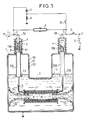
- the reference 1 designates a metallic cryostat consisting of two walls 50 and 51 separated by a space 52 maintained under vacuum.
- the cryostat is partially filled with a fluid 2 at a temperature allowing the winding used to take on the superconductive state.
- the fluid used is liquid helium.
- the tank is surmounted by two insulating bushings 3 and 4 through which conductors 5A and 5B pass respectively, each provided with an insulating sheath 10A, 10B.
- the conductor 5A, 5B is made of solid copper.
- the cryostat is inserted in line L to be cut between a point F (connected to bushing 3) and a point G (connected to crossing 4).
- a circuit breaker D with low breaking capacity, is inserted in series in the line on the use side.
- the conductor 5A is split over its entire length into two equal parts 5 ′ and 5 ⁇ , up to a point Q in the liquid part of the fluid.
- the parts 5 'and 5' are isolated from each other and surrounded by an insulating sheath 10A, coated, inside the cryostat, by a conductive layer 30A connected to the potential of the tank.
- the end of this layer 30A is electrically connected to a guard ring 31A, placed in the liquid part.
- the conductors 5 ′ and 5 ⁇ are respectively connected to conductors of superconductive material 7 and 8, wound respectively around two coaxial cylindrical insulating sleeves 14 and 15, held by insulating supports 16 and 17 fixed to the tank. Holes 18 and 19 in the supports allow the cryogenic liquid to circulate inside the sleeves.
- the winding of the two wires 7 and 8 on their respective sleeves is carried out in the opposite direction to cancel the value of the self-inductance of the assembly.
- a circuit comprising, connected in series, a capacitor C and an IF switch with rapid closure.
- the point common to the capacitor C and to the switch IF is connected to earth by a resistor R of high ohmic value.
- a variable value resistor with the voltage across its terminals such as a varistor V, is connected between the terminals of the cryostat.
- the operation of the device is as follows: - in normal line operation, the circuit breaker D is closed and the IF switch is open. The capacitor C is thus permanently charged by the line on the upstream side through the resistor R. - during a fault, symbolized in the figure by the broken line E, the current I in the line increases rapidly and very quickly reaches the critical value Ic, causing the transition of the windings 7 and 8 which become highly resistive. An overvoltage then occurs and the varistor V operates. A large part of the electromagnetic energy is absorbed by the varistor V. The residual current in the windings is easily cut by the circuit breaker D. The discharge of the capacitor n is not necessary in this case and does not intervene. The line is immediately protected without the need for rapid fault detection.
- the switch IF is closed. This closure causes the capacitor C to discharge through the superconductive windings, which produces an additional current which is added to the current to be cut; in this way, the current in the windings reaches a value slightly greater than the critical value, which produces the transition from the windings to the resistive state.
- the residual current in the windings is easily cut by the circuit breaker D.
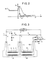
- FIG. 2 is a diagram showing, in solid lines, the shape of the current in the superconductive windings before and after the closing of the switch IF, which is carried out at time to; there is shown in dashed lines the shape that the discharge current of the capacitor would have if the transition did not occur.
- the ascending part of the first half-pseudo period is added to the current to be cut, the value of which can thus reach the critical value.
- the dashed line shows the total current flowing through the circuit breaker D after the varistor V has operated.
- Time t1 is the instant at which the residual current is cut by circuit breaker D.
- the device can operate with a discharge current of 1000 amps for the first peak value, which is perfectly achievable with a low power capacitor. To cut a current lower than the nominal current, it will be necessary to increase the intensity of the discharge current to reach the critical current Ic.
- the circuit breaker D will be opened as quickly as possible, then the IF switch will be opened.
- the circuit breaker After the transient regime, at the voltage restored on the windings, the varistor returns to its normal state and no longer conducts a very weak current.
- the circuit breaker has a breaking capacity calculated to cut the residual resistive current flowing in the windings increased by the current on in the varistor.
- the cryostat 1 comprises a third crossing referenced 100 by which the connecting wires exit from two superconductive windings 70 and 80 arranged like the windings 7 and 8. These windings are connected on one side at point G at the end of the crossing 4 and, on the other side, at a point H of the line via, on the winding 80, a switch O shunted by a resistor R1 and, optionally, on each of the branches 70 and 80, respectively two resistors R2 and R3 having low and equal initial values.
- the circuit breaker D is placed downstream of point H; varistor V is placed between bushings 3 and 100; a disconnector S connects points G and H.
- the windings 70 and 80 have a smaller section than the windings 7 and 8 and therefore a lower value of the critical current, a lower nominal current and a higher value of resistance in the non-superconductive state.
- the value of the critical current of the windings 70 and 80 is chosen to be slightly greater than the residual current of the windings 7 and 8 when the latter have passed in the non-superconductive state.
- the operation of the device is as follows: - in operating mode of the line, the devices S and D as well as the switch O are closed.
- the nominal current In passes through the windings 7 and 8, the disconnector S and the circuit breaker D.
- the windings 7 and 8 pass in the non-superconductive state, as has been explained with reference to FIG. 1.
- the disconnector S is then opened.
- the residual current then passes through the windings 70 and 80; the switch O is then opened; the value of the resistance of the branch 80 increases because of the arc resistance, which causes the transfer of all the residual current in the winding 70 and the transition to the non-superconductive state of the latter, followed by the transfer of all of the above-mentioned residual current to the winding 80 which in turn transits to the non-superconductive state.
- a high-value resistor has thus been introduced into the line, which greatly reduces the residual current which the circuit breaker D is then able to cut without having a high breaking capacity. It is noted that the varistor V also limits the overvoltage caused by the transition of the winding 80, after that of the windings 7 and 8.
- the DC circuit breakers according to the invention make it possible to cut the DC currents whatever their intensity.
- they have the following two advantages compared to circuit breakers of known type: - They make it possible to limit the fault current of large amplitude in a very short time, of the order of a millisecond instead of fifty milliseconds, or even more, in the prior art.
- Conventional circuit breakers do not offer the possibility of limiting the current so that the large amplitude of current flows over the network.
Landscapes
- Engineering & Computer Science (AREA)
- Power Engineering (AREA)
- Emergency Protection Circuit Devices (AREA)
- Containers, Films, And Cooling For Superconductive Devices (AREA)
- Driving Mechanisms And Operating Circuits Of Arc-Extinguishing High-Tension Switches (AREA)
Applications Claiming Priority (2)
| Application Number | Priority Date | Filing Date | Title |
|---|---|---|---|
| FR8902408A FR2643743B1 (fr) | 1989-02-24 | 1989-02-24 | Dispositif de coupure pour courant continu a haute tension |
| FR8902408 | 1989-02-24 |
Publications (1)
| Publication Number | Publication Date |
|---|---|
| EP0384346A1 true EP0384346A1 (de) | 1990-08-29 |
Family
ID=9379089
Family Applications (1)
| Application Number | Title | Priority Date | Filing Date |
|---|---|---|---|
| EP90103134A Withdrawn EP0384346A1 (de) | 1989-02-24 | 1990-02-19 | Unterbrechungsvorrichtung für Hochspannungsgleichstrom |
Country Status (3)
| Country | Link |
|---|---|
| EP (1) | EP0384346A1 (de) |
| JP (1) | JPH02260343A (de) |
| FR (1) | FR2643743B1 (de) |
Cited By (5)
| Publication number | Priority date | Publication date | Assignee | Title |
|---|---|---|---|---|
| WO2016092182A1 (fr) * | 2014-12-11 | 2016-06-16 | Supergrid Institute | Dispositif de coupure de courant continu haute tension |
| FR3094136A1 (fr) | 2019-03-22 | 2020-09-25 | Supergrid Institute | Dispositif de coupure de courant pour courant continu haute tension avec résonateur et commutation |
| US10998710B2 (en) | 2017-01-31 | 2021-05-04 | Supergrid Institute | High-voltage DC cut-off device |
| US11791617B2 (en) | 2018-12-27 | 2023-10-17 | Supergrid Institute | Current cut-off device for high-voltage direct current with capacitive buffer circuit, and control method |
| US11824346B2 (en) | 2018-12-27 | 2023-11-21 | Supergrid Institute | Current cut-off device for high-voltage direct current with adaptive oscillatory circuit, and control method |
Citations (4)
| Publication number | Priority date | Publication date | Assignee | Title |
|---|---|---|---|---|
| CH495074A (de) * | 1965-08-31 | 1970-08-15 | Siemens Ag | Schaltvorrichtung für supraleitende Starkstromkabel |
| FR2105430A5 (de) * | 1970-09-07 | 1972-04-28 | Comp Generale Electricite | |
| US3704391A (en) * | 1970-11-10 | 1972-11-28 | Ite Imperial Corp | Cryogenic current limiting switch |
| US3736439A (en) * | 1969-05-23 | 1973-05-29 | Siemens Ag | Current-limiting switch employing low temperature resistor |
-
1989
- 1989-02-24 FR FR8902408A patent/FR2643743B1/fr not_active Expired - Lifetime
-
1990
- 1990-02-19 EP EP90103134A patent/EP0384346A1/de not_active Withdrawn
- 1990-02-20 JP JP2039559A patent/JPH02260343A/ja active Pending
Patent Citations (4)
| Publication number | Priority date | Publication date | Assignee | Title |
|---|---|---|---|---|
| CH495074A (de) * | 1965-08-31 | 1970-08-15 | Siemens Ag | Schaltvorrichtung für supraleitende Starkstromkabel |
| US3736439A (en) * | 1969-05-23 | 1973-05-29 | Siemens Ag | Current-limiting switch employing low temperature resistor |
| FR2105430A5 (de) * | 1970-09-07 | 1972-04-28 | Comp Generale Electricite | |
| US3704391A (en) * | 1970-11-10 | 1972-11-28 | Ite Imperial Corp | Cryogenic current limiting switch |
Cited By (11)
| Publication number | Priority date | Publication date | Assignee | Title |
|---|---|---|---|---|
| WO2016092182A1 (fr) * | 2014-12-11 | 2016-06-16 | Supergrid Institute | Dispositif de coupure de courant continu haute tension |
| FR3030105A1 (fr) * | 2014-12-11 | 2016-06-17 | Inst Supergrid | Dispositif de coupure de courant continu haute tension |
| CN107005045A (zh) * | 2014-12-11 | 2017-08-01 | 超级电力研究所 | 高压直流电流断路装置 |
| CN107005045B (zh) * | 2014-12-11 | 2019-09-27 | 超级电力研究所 | 高压直流电流断路装置 |
| US10468873B2 (en) | 2014-12-11 | 2019-11-05 | Supergrid Institute | High voltage DC current tripout device |
| US10998710B2 (en) | 2017-01-31 | 2021-05-04 | Supergrid Institute | High-voltage DC cut-off device |
| US11791617B2 (en) | 2018-12-27 | 2023-10-17 | Supergrid Institute | Current cut-off device for high-voltage direct current with capacitive buffer circuit, and control method |
| US11824346B2 (en) | 2018-12-27 | 2023-11-21 | Supergrid Institute | Current cut-off device for high-voltage direct current with adaptive oscillatory circuit, and control method |
| FR3094136A1 (fr) | 2019-03-22 | 2020-09-25 | Supergrid Institute | Dispositif de coupure de courant pour courant continu haute tension avec résonateur et commutation |
| WO2020193906A1 (fr) | 2019-03-22 | 2020-10-01 | Supergrid Institute | Dispositif de coupure de courant pour courant continu haute tension avec résonateur et commutation |
| US11798763B2 (en) | 2019-03-22 | 2023-10-24 | Supergrid Institute | Current cut-off device for high-voltage direct current with resonator and switching |
Also Published As
| Publication number | Publication date |
|---|---|
| JPH02260343A (ja) | 1990-10-23 |
| FR2643743B1 (fr) | 1991-05-10 |
| FR2643743A1 (fr) | 1990-08-31 |
Similar Documents
| Publication | Publication Date | Title |
|---|---|---|
| FR2655767A1 (fr) | Disjoncteur limiteur a courant continu a haute tension. | |
| EP0228584B1 (de) | Einrichtung zur Wechselstrombegrenzung | |
| CH676067A5 (de) | ||
| FR2666912A1 (fr) | Dispositif limiteur de courant a supraconducteur. | |
| WO2009063150A1 (fr) | Systeme de creation d'un champ magnetique via un aimant supraconducteur | |
| EP3942585B1 (de) | Stromabschaltvorrichtung für hochspannungsgleichstrom mit resonator und schaltung | |
| FR3062512A1 (fr) | Dispositif de coupure de courant continu haute tension | |
| CA2040983A1 (fr) | Limiteur de courant hybride | |
| EP0817346B1 (de) | Schutzvorrichtung gegen die Folgen von internen Fehlern in einem elektrischen Gerät | |
| FR3042656A1 (fr) | Equipement d’interconnexion pour reseau haute tension continue | |
| EP0224535B1 (de) | Statischer schalter oder schaltgerät zur geschützten versorgung einer last und ihrer leitung | |
| EP0384346A1 (de) | Unterbrechungsvorrichtung für Hochspannungsgleichstrom | |
| EP1102379A1 (de) | Schutzsystem für einen Dreiphasenverteiltransformator mit einer durch ein dielektrisches Fluidum unterstützten Isolierung mit einem Mikroschalter | |
| FR2661288A1 (fr) | Limiteur de courant hybride. | |
| EP0749140B1 (de) | Unterbrechungsvorrichtung für Hochspannungsgleichstrom | |
| FR2659805A1 (fr) | Limiteur de courant a bobine supraconductrice. | |
| FR2686466A1 (fr) | Dispositif supraconducteur a limitation de courant controlee. | |
| FR2621749A1 (fr) | Limiteur de courant de defaut pour ligne triphasee | |
| FR2733353A1 (fr) | Limiteur de courant de court-circuit pour reseau a haute tension | |
| FR2621734A1 (fr) | Disjoncteur a haute tension a courant continu | |
| FR2636477A1 (fr) | Limiteur de courant cryogenique | |
| EP4385107A1 (de) | Vorrichtung und verfahren zum trennen eines hochspannungsgleichstroms mit einer sicherung und schwingstromüberlastungssystem | |
| WO2022029379A2 (fr) | Dispositif de coupure de courant pour courant électrique sous haute tension continue, installation avec un tel dispositif, procede de pilotage, et processus d'evaluation de l'integrite d'un conducteur electrique | |
| FR2723247A1 (fr) | Limiteur de courant inductif avec supraconducteur a haute temperature critique | |
| FR2650078A1 (fr) | Systeme de detection de defaut d'isolement d'une ligne de distribution d'energie electrique moyenne tension |
Legal Events
| Date | Code | Title | Description |
|---|---|---|---|
| PUAI | Public reference made under article 153(3) epc to a published international application that has entered the european phase |
Free format text: ORIGINAL CODE: 0009012 |
|
| AK | Designated contracting states |
Kind code of ref document: A1 Designated state(s): AT BE CH DE DK ES FR GB GR IT LI LU NL SE |
|
| 17P | Request for examination filed |
Effective date: 19901227 |
|
| STAA | Information on the status of an ep patent application or granted ep patent |
Free format text: STATUS: THE APPLICATION IS DEEMED TO BE WITHDRAWN |
|
| 18D | Application deemed to be withdrawn |
Effective date: 19920902 |