EP0384316A2 - Embossed plate heat exchanger - Google Patents
Embossed plate heat exchanger Download PDFInfo
- Publication number
- EP0384316A2 EP0384316A2 EP90103022A EP90103022A EP0384316A2 EP 0384316 A2 EP0384316 A2 EP 0384316A2 EP 90103022 A EP90103022 A EP 90103022A EP 90103022 A EP90103022 A EP 90103022A EP 0384316 A2 EP0384316 A2 EP 0384316A2
- Authority
- EP
- European Patent Office
- Prior art keywords
- plate
- projections
- heat exchanger
- fin type
- type heat
- Prior art date
- Legal status (The legal status is an assumption and is not a legal conclusion. Google has not performed a legal analysis and makes no representation as to the accuracy of the status listed.)
- Granted
Links
- 239000012530 fluid Substances 0.000 claims abstract description 23
- 230000002093 peripheral effect Effects 0.000 claims abstract description 16
- 230000013011 mating Effects 0.000 claims description 8
- 230000007423 decrease Effects 0.000 claims description 3
- 229910003460 diamond Inorganic materials 0.000 claims description 2
- 239000010432 diamond Substances 0.000 claims description 2
- 239000010705 motor oil Substances 0.000 abstract description 6
- 230000005540 biological transmission Effects 0.000 abstract description 3
- 238000001816 cooling Methods 0.000 abstract description 3
- 229910052782 aluminium Inorganic materials 0.000 description 6
- XAGFODPZIPBFFR-UHFFFAOYSA-N aluminium Chemical compound [Al] XAGFODPZIPBFFR-UHFFFAOYSA-N 0.000 description 6
- 239000000463 material Substances 0.000 description 6
- 239000007788 liquid Substances 0.000 description 5
- 210000002445 nipple Anatomy 0.000 description 5
- 238000004519 manufacturing process Methods 0.000 description 4
- 238000004378 air conditioning Methods 0.000 description 3
- 239000011324 bead Substances 0.000 description 2
- 230000003247 decreasing effect Effects 0.000 description 2
- 229910052751 metal Inorganic materials 0.000 description 2
- 239000002184 metal Substances 0.000 description 2
- 239000003507 refrigerant Substances 0.000 description 2
- 229910001369 Brass Inorganic materials 0.000 description 1
- 229910045601 alloy Inorganic materials 0.000 description 1
- 239000000956 alloy Substances 0.000 description 1
- 239000010951 brass Substances 0.000 description 1
- 238000005219 brazing Methods 0.000 description 1
- 238000005253 cladding Methods 0.000 description 1
- 238000004049 embossing Methods 0.000 description 1
- 230000008020 evaporation Effects 0.000 description 1
- 238000001704 evaporation Methods 0.000 description 1
- 238000000034 method Methods 0.000 description 1
- 238000012986 modification Methods 0.000 description 1
- 230000004048 modification Effects 0.000 description 1
- 239000010935 stainless steel Substances 0.000 description 1
- 229910001220 stainless steel Inorganic materials 0.000 description 1
- 230000008016 vaporization Effects 0.000 description 1
Images

Classifications
-
- F—MECHANICAL ENGINEERING; LIGHTING; HEATING; WEAPONS; BLASTING
- F28—HEAT EXCHANGE IN GENERAL
- F28F—DETAILS OF HEAT-EXCHANGE AND HEAT-TRANSFER APPARATUS, OF GENERAL APPLICATION
- F28F3/00—Plate-like or laminated elements; Assemblies of plate-like or laminated elements
- F28F3/02—Elements or assemblies thereof with means for increasing heat-transfer area, e.g. with fins, with recesses, with corrugations
- F28F3/04—Elements or assemblies thereof with means for increasing heat-transfer area, e.g. with fins, with recesses, with corrugations the means being integral with the element
- F28F3/042—Elements or assemblies thereof with means for increasing heat-transfer area, e.g. with fins, with recesses, with corrugations the means being integral with the element in the form of local deformations of the element
- F28F3/044—Elements or assemblies thereof with means for increasing heat-transfer area, e.g. with fins, with recesses, with corrugations the means being integral with the element in the form of local deformations of the element the deformations being pontual, e.g. dimples
-
- F—MECHANICAL ENGINEERING; LIGHTING; HEATING; WEAPONS; BLASTING
- F28—HEAT EXCHANGE IN GENERAL
- F28D—HEAT-EXCHANGE APPARATUS, NOT PROVIDED FOR IN ANOTHER SUBCLASS, IN WHICH THE HEAT-EXCHANGE MEDIA DO NOT COME INTO DIRECT CONTACT
- F28D1/00—Heat-exchange apparatus having stationary conduit assemblies for one heat-exchange medium only, the media being in contact with different sides of the conduit wall, in which the other heat-exchange medium is a large body of fluid, e.g. domestic or motor car radiators
- F28D1/02—Heat-exchange apparatus having stationary conduit assemblies for one heat-exchange medium only, the media being in contact with different sides of the conduit wall, in which the other heat-exchange medium is a large body of fluid, e.g. domestic or motor car radiators with heat-exchange conduits immersed in the body of fluid
- F28D1/03—Heat-exchange apparatus having stationary conduit assemblies for one heat-exchange medium only, the media being in contact with different sides of the conduit wall, in which the other heat-exchange medium is a large body of fluid, e.g. domestic or motor car radiators with heat-exchange conduits immersed in the body of fluid with plate-like or laminated conduits
- F28D1/0308—Heat-exchange apparatus having stationary conduit assemblies for one heat-exchange medium only, the media being in contact with different sides of the conduit wall, in which the other heat-exchange medium is a large body of fluid, e.g. domestic or motor car radiators with heat-exchange conduits immersed in the body of fluid with plate-like or laminated conduits the conduits being formed by paired plates touching each other
- F28D1/0325—Heat-exchange apparatus having stationary conduit assemblies for one heat-exchange medium only, the media being in contact with different sides of the conduit wall, in which the other heat-exchange medium is a large body of fluid, e.g. domestic or motor car radiators with heat-exchange conduits immersed in the body of fluid with plate-like or laminated conduits the conduits being formed by paired plates touching each other the plates having lateral openings therein for circulation of the heat-exchange medium from one conduit to another
- F28D1/0333—Heat-exchange apparatus having stationary conduit assemblies for one heat-exchange medium only, the media being in contact with different sides of the conduit wall, in which the other heat-exchange medium is a large body of fluid, e.g. domestic or motor car radiators with heat-exchange conduits immersed in the body of fluid with plate-like or laminated conduits the conduits being formed by paired plates touching each other the plates having lateral openings therein for circulation of the heat-exchange medium from one conduit to another the plates having integrated connecting members
-
- F—MECHANICAL ENGINEERING; LIGHTING; HEATING; WEAPONS; BLASTING
- F28—HEAT EXCHANGE IN GENERAL
- F28F—DETAILS OF HEAT-EXCHANGE AND HEAT-TRANSFER APPARATUS, OF GENERAL APPLICATION
- F28F3/00—Plate-like or laminated elements; Assemblies of plate-like or laminated elements
- F28F3/02—Elements or assemblies thereof with means for increasing heat-transfer area, e.g. with fins, with recesses, with corrugations
- F28F3/025—Elements or assemblies thereof with means for increasing heat-transfer area, e.g. with fins, with recesses, with corrugations the means being corrugated, plate-like elements
-
- F—MECHANICAL ENGINEERING; LIGHTING; HEATING; WEAPONS; BLASTING
- F28—HEAT EXCHANGE IN GENERAL
- F28D—HEAT-EXCHANGE APPARATUS, NOT PROVIDED FOR IN ANOTHER SUBCLASS, IN WHICH THE HEAT-EXCHANGE MEDIA DO NOT COME INTO DIRECT CONTACT
- F28D21/00—Heat-exchange apparatus not covered by any of the groups F28D1/00 - F28D20/00
- F28D2021/0019—Other heat exchangers for particular applications; Heat exchange systems not otherwise provided for
- F28D2021/008—Other heat exchangers for particular applications; Heat exchange systems not otherwise provided for for vehicles
- F28D2021/0089—Oil coolers
-
- Y—GENERAL TAGGING OF NEW TECHNOLOGICAL DEVELOPMENTS; GENERAL TAGGING OF CROSS-SECTIONAL TECHNOLOGIES SPANNING OVER SEVERAL SECTIONS OF THE IPC; TECHNICAL SUBJECTS COVERED BY FORMER USPC CROSS-REFERENCE ART COLLECTIONS [XRACs] AND DIGESTS
- Y10—TECHNICAL SUBJECTS COVERED BY FORMER USPC
- Y10S—TECHNICAL SUBJECTS COVERED BY FORMER USPC CROSS-REFERENCE ART COLLECTIONS [XRACs] AND DIGESTS
- Y10S165/00—Heat exchange
- Y10S165/454—Heat exchange having side-by-side conduits structure or conduit section
- Y10S165/464—Conduits formed by joined pairs of matched plates
- Y10S165/465—Manifold space formed in end portions of plates
-
- Y—GENERAL TAGGING OF NEW TECHNOLOGICAL DEVELOPMENTS; GENERAL TAGGING OF CROSS-SECTIONAL TECHNOLOGIES SPANNING OVER SEVERAL SECTIONS OF THE IPC; TECHNICAL SUBJECTS COVERED BY FORMER USPC CROSS-REFERENCE ART COLLECTIONS [XRACs] AND DIGESTS
- Y10—TECHNICAL SUBJECTS COVERED BY FORMER USPC
- Y10S—TECHNICAL SUBJECTS COVERED BY FORMER USPC CROSS-REFERENCE ART COLLECTIONS [XRACs] AND DIGESTS
- Y10S165/00—Heat exchange
- Y10S165/916—Oil cooler
Definitions
- This invention relates to heat exchangers, and in particular, to air cooled exchangers for cooling viscous fluids such as automotive engine oils, transmission fluid and power steering fluid.
- heat exchangers employed for liquid-to-air heat exchange of high viscosity/low thermal conductivity fluids such as engine oil, transmission fluid, transaxle fluids or hydraulic fluids have been commonly produced in three main designs.
- the first design is an extruded tube and fin design wherein one or more tubular channels is extruded with integral internal fins.
- a difficulty with this design is that the heat transfer per volume of fluid flowing through the exchanger is usually relatively low, although the flow resistance or pressure drop through the exchanger also tends to be relatively low.
- the second common design consists of a bank of extruded or weld-seam tubes with expanded metal turbulizers located inside each tube and exterior cooling fins located between and in contact with the exterior of the tubes.
- This type of heat exchanger generally exhibits higher heat transfer due to the greater liquid flow turbulization by the turbulizer inside the tubes, however, the flow resistance or pressure drop in the liquid flow through the tubes is undesirably high, and the use of a turbulizer naturally increases the manufacturing costs of the heat exchanger.
- the third common design for these liquid-to-air heat exchangers is a plate and fin design in which an expanded metal turbulizer is installed between a pair of mating elongate plates.
- this type of heat exchanger produces undesirably high liquid flow resistance and the manufacturing cost is high because of the extra steps involved in inserting the turbulizer and the necessity of ensuring that a good bond is achieved between the turbulizer and the plate.
- Plate and fin type heat exchangers without turbulizers have been used in other applications, such as automotive air conditioning evaporators.
- An example of such a device is shown in United States Patent No. 4,470,455 issued September 11, 1984 to DEMETRIO B. SACCA.
- This patent shows a heat exchanger formed of a plurality of stacked pairs of plates, the plates having rows of overlapping ribs angled obliquely to the flow path. This provides a circuitous or tortuous flow path through the plate pair. While this may be good for the evaporation of refrigerant, it would not be acceptable for high viscosity/low thermal conductivity fluids such as engine oils or hydraulic fluids, because the pressure drop through this type of exchanger would be unacceptably high.
- the present invention is a plate and fin heat exchanger which achieves a high heat transfer performance-to-liquid side pressure drop ratio and a high heat transfer performance-to-weight ratio through the use of non-overlapping, uniformly spaced-apart mating projections formed in the plates.
- a plate and fin type heat exchanger comprising a plurality of elongate plates each having a planar central portion, a raised co-planar peripheral edge portion located above the plane of the central portion, and opposed co-planar end bosses located below the plane of the central portion.
- the plates are arranged face-to-face in a plurality of stacked pairs, the bosses having openings formed therein to form respective headers at each end of the plates for flow of fluid through the plate pairs.
- the central portions have a plurality of uniformly spaced-apart projections extending to the plane of the peripheral edge portions, the projections and the peripheral edge portions of each plate pair being joined together, the projections being spaced-apart so that there is no overlap therebetween longitudinally or transversely of the plates.
- corrugated fins are located between each plate pair extending between the end bosses and in contact with the respective plate central portions.
- Heat exchanger 10 has a plurality of stacked plate pairs including an upper plate pair 12, a plurality of intermediate plate pairs 14 and a lower plate pair 16. Fin strips 18 are located between the adjacent plate pairs.
- An upper mounting plate 20 is attached to upper plate pair 12 and a lower mounting plate 22 is attached to lower plate pair 16.
- Upper mounting plate 20 includes nipples 24 which communicate with flow headers 26 formed by bosses 28 on each plate pair as will be described further below.
- One of the nipples 24 acts as a flow inlet and the other nipple 24 acts as a flow outlet.
- mounting plates 20, 22 can be eliminated and other inlet and outlet means could be employed for flow of fluid between the headers 26, as will be apparent to those skilled in the art.
- an intermediate plate pair 14 (only one of which is shown in Figure 2 for clarity) includes a pair of identical elongate plates 30 arranged face-to-face.
- Each plate 30 includes a planar central portion 32, a raised co-planar peripheral edge portion 34 located above the plane of central portion 32 and, as mentioned above, opposed, co-planar end bosses 28 located below the plane of central portion 32 when plate 30 is shown face up, and above the plane of central portion 32 when plate 30 is shown face down.
- Bosses 28 have openings 36 formed therein, so that when a plurality of plate pairs 14 are stacked vertically, the bosses at respective ends of the plate pairs form respective headers 26 (see Figure 1) for parallel flow of fluid through the plate pairs.
- the planar central portions 32 are formed with a plurality of uniformly spaced-apart projections 38, which extend inwardly to the plane of the peripheral edge portions 34.
- the projections 38 and the peripheral edge portions 34 are joined together when the plate pairs are assembled.
- Projections 38 have generally flat tops 40 and vertical side walls 42, so that the mating projections 38 form symmetrical blunt-sided flow restrictions inside the plate pairs.
- vertical is used in association with vertical sides 42, it will be appreciated that some angle is required to suit the draw and tool requirements for forming plates 30. However, the angle from the vertical of sides 40 should not exceed 10 degrees. Also, some slight rounding of flat tops 40 may occur during manufacture of plates 30 depending upon the thickness of the material used to form the plates.
- the terms “vertical sides” and “flat tops” are intended to include respectively, some angle to the vertical and some rounding as mentioned above.
- Projections 38 are formed in central plate portions 32 by an embossing process.
- projections 38 are located in longitudinal rows and are spaced apart or at least juxtaposed, so that there is no longitudinal or transverse overlap with respect to the projections in the adjacent rows.
- the longitudinal rows thus provide longitudinal flow passages between the rows of projections.
- Projections 38 are circular in plan view and are spaced apart such that adjacent projections are located in a diamond pattern, any three adjacent projections being located at the apexes of an equilateral triangle.
- half projections 44 are formed partially in central portions 32 and partially in the peripheral edge portions 34. Half projections 44 are spaced equidistant from the adjacent full projections 38 in planar central portions 32, again maintaining the equilateral triangle spacing relationship mentioned above.
- the thermal resistance of plates 30 decreases, or in other words, the heat transfer efficiency or performance increases.
- increasing the number of projections and decreasing the spacing therebetween also increases the flow resistance or pressure drop through the heat exchanger. In the preferred embodiment, for any given or predetermined pressure drop limit for heat exchanger 10, the number of projections is maximized.
- upper plate pair 12 and lower plate pair 16 have elongate plates 46 adjacent to respective mounting plates 20, 22.
- Plates 46 are identical to plates 30, except that the bosses 28 are eliminated, so that plates 46 fit flush against the mating surfaces of mounting plates 20, 22.
- Lower mounting plate 22 covers openings 36 in its adjacent plate 46 and thus acts as a baffle.
- Upper mounting plate 20 acts in a similar manner as a baffle, so that fluid flows downwardly through one nipple 24 into header 26, and then continues to flow in parallel fashion through all of the plate pairs to the opposite header and then exits through the other nipple 24.
- corrugated fin strips 18 are shown having a plurality of transverse louvers 48 formed therein. Louvers 48 are disposed perpendicularly to the flow of fluid through fins 18. It will be noted that the louvers 48 decrease in length toward the peripheral sides of the fins. This improves heat transfer through the fins where the fins overly the dimples formed in plate central portions 32 by projections 38, 44, by improving transverse heat flow in the fin to the louvres.
- the assembly of heat exchanger 10 involves the stacking of plate pairs 12, 14 and 16 with fin strips 18 located therebetween. Mounting plates 20, 22 are then added and the entire assembly is furnace brazed to join all contacting surfaces.
- plates 30, 46 are formed of aluminum with an aluminum brazing alloy cladding or layer formed thereon.
- Fin strips 18 are formed of plain aluminum and mounting plates 20, 22 are also formed of plain aluminum or any other material that can be brazed to the adjacent plates 46.
- plates 30, 46 are about 28 centimeters in length and 2 centimeters in width and are formed of aluminum sheet material which is about 0.05 centimeters in thickness.
- Fin strips 18 are formed of any suitable aluminum finning material. Fin strips 18 are typically 2 centimeters in width, 22 centimeters in length and 0.5 centimeters in height.
- heat exchanger 10 could be varied in length, width or height.
- mounting plates 20, 22 can be eliminated or replaced with other means to direct the liquid flow through the heat exchanger.
- plate 46 of the lower plate pair 16 can be produced without openings 36 and it may be desirable to do this if there is a potential leak problem.
- Baffling could be incorporated into the heat exchanger to vary the flow path or circuit therein and change the heat transfer and pressure drop characteristics of the heat exchanger to suit particular needs.
- Other materials could be used for heat exchanger 10, such as stainless steel or brass.
- the size and spacing of the projections may be varied somewhat in keeping with the parameters discussed above.
- the heat exchanger of the present invention is a high performance liquid-to-air heat exchanger that does not require a turbulizer and which is easy to manufacture.
Abstract
Description
- This invention relates to heat exchangers, and in particular, to air cooled exchangers for cooling viscous fluids such as automotive engine oils, transmission fluid and power steering fluid.
- In the past, heat exchangers employed for liquid-to-air heat exchange of high viscosity/low thermal conductivity fluids such as engine oil, transmission fluid, transaxle fluids or hydraulic fluids have been commonly produced in three main designs. The first design is an extruded tube and fin design wherein one or more tubular channels is extruded with integral internal fins. A difficulty with this design is that the heat transfer per volume of fluid flowing through the exchanger is usually relatively low, although the flow resistance or pressure drop through the exchanger also tends to be relatively low. There is also a practical limitation as to the depth of the integral internal fins in the tubes that can be extruded and the weight of this type of exchanger is relatively high.
- The second common design consists of a bank of extruded or weld-seam tubes with expanded metal turbulizers located inside each tube and exterior cooling fins located between and in contact with the exterior of the tubes. This type of heat exchanger generally exhibits higher heat transfer due to the greater liquid flow turbulization by the turbulizer inside the tubes, however, the flow resistance or pressure drop in the liquid flow through the tubes is undesirably high, and the use of a turbulizer naturally increases the manufacturing costs of the heat exchanger.
- The third common design for these liquid-to-air heat exchangers is a plate and fin design in which an expanded metal turbulizer is installed between a pair of mating elongate plates. Again, this type of heat exchanger produces undesirably high liquid flow resistance and the manufacturing cost is high because of the extra steps involved in inserting the turbulizer and the necessity of ensuring that a good bond is achieved between the turbulizer and the plate.
- Plate and fin type heat exchangers without turbulizers have been used in other applications, such as automotive air conditioning evaporators. An example of such a device is shown in United States Patent No. 4,470,455 issued September 11, 1984 to DEMETRIO B. SACCA. This patent shows a heat exchanger formed of a plurality of stacked pairs of plates, the plates having rows of overlapping ribs angled obliquely to the flow path. This provides a circuitous or tortuous flow path through the plate pair. While this may be good for the evaporation of refrigerant, it would not be acceptable for high viscosity/low thermal conductivity fluids such as engine oils or hydraulic fluids, because the pressure drop through this type of exchanger would be unacceptably high.
- Another example of an automotive air conditioning evaporator using stacked plate pairs without a turbulizer is disclosed in United States Patent No. 4,600,053 issued July 15, 1986 to R. L. PATEL et al. This patent shows a plurality of rows of overlapping dissimilar mating beads said to increase the heat transfer co-efficient of the heat exchanger. Again, however, since this is an air conditioning evaporator for vaporizing refrigerant, flow resistance and pressure drop is not a major concern. This type of heat exchanger could not be used for high viscosity/low thermal conductivity fluids such as engine oils or hydraulic fluids, again because the pressure drop through the exchanger would be unacceptably high, or in other words, the heat transfer efficiency of the exchanger would be unacceptably low. Also, the dissimilar mating beads would not produce sufficient vorticity or turbulence for engine oils and hydraulic fluids.
- The present invention is a plate and fin heat exchanger which achieves a high heat transfer performance-to-liquid side pressure drop ratio and a high heat transfer performance-to-weight ratio through the use of non-overlapping, uniformly spaced-apart mating projections formed in the plates.
- According to the invention, there is provided a plate and fin type heat exchanger comprising a plurality of elongate plates each having a planar central portion, a raised co-planar peripheral edge portion located above the plane of the central portion, and opposed co-planar end bosses located below the plane of the central portion. The plates are arranged face-to-face in a plurality of stacked pairs, the bosses having openings formed therein to form respective headers at each end of the plates for flow of fluid through the plate pairs. The central portions have a plurality of uniformly spaced-apart projections extending to the plane of the peripheral edge portions, the projections and the peripheral edge portions of each plate pair being joined together, the projections being spaced-apart so that there is no overlap therebetween longitudinally or transversely of the plates. Also, corrugated fins are located between each plate pair extending between the end bosses and in contact with the respective plate central portions.
- A preferred embodiment of the invention will now be described, by way of example, with reference to the accompanying drawings, in which:
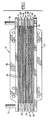
- Figure 1 is an elevational view broken away to indicate indeterminate length of a preferred embodiment of a heat exchanger according to the present invention;
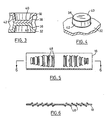
- Figure 2 is an exploded perspective view of the heat exchanger of Figure 1 showing only three plate pairs for the purposes of simplicity of illustration;
- Figure 3 is a cross sectional view of a pair of mating projections taken along lines 3-3 of Figure 2;
- Figure 4 is a perspective view of a single projection as indicated by circle 4 in Figure 2;
- Figure 5 is an elevational view taken along
arrow 5 in Figure 2 showing one leg of the fin strip; and - Figure 6 is a cross sectional view taken along lines 6-6 of Figure 5.
- Referring to the drawings, a preferred embodiment of a heat exchanger according to the present invention is generally indicated in Figure 1 by
reference numeral 10.Heat exchanger 10 has a plurality of stacked plate pairs including anupper plate pair 12, a plurality ofintermediate plate pairs 14 and alower plate pair 16.Fin strips 18 are located between the adjacent plate pairs. Anupper mounting plate 20 is attached toupper plate pair 12 and alower mounting plate 22 is attached tolower plate pair 16. -
Upper mounting plate 20 includesnipples 24 which communicate withflow headers 26 formed bybosses 28 on each plate pair as will be described further below. One of thenipples 24 acts as a flow inlet and theother nipple 24 acts as a flow outlet. If desired,mounting plates headers 26, as will be apparent to those skilled in the art. - Referring in particular to Figures 2, 3 and 4, an intermediate plate pair 14 (only one of which is shown in Figure 2 for clarity) includes a pair of identical
elongate plates 30 arranged face-to-face. Eachplate 30 includes a planarcentral portion 32, a raised co-planarperipheral edge portion 34 located above the plane ofcentral portion 32 and, as mentioned above, opposed,co-planar end bosses 28 located below the plane ofcentral portion 32 whenplate 30 is shown face up, and above the plane ofcentral portion 32 whenplate 30 is shown face down.Bosses 28 haveopenings 36 formed therein, so that when a plurality ofplate pairs 14 are stacked vertically, the bosses at respective ends of the plate pairs form respective headers 26 (see Figure 1) for parallel flow of fluid through the plate pairs. - Referring in particular to Figures 3 and 4, the planar
central portions 32 are formed with a plurality of uniformly spaced-apart projections 38, which extend inwardly to the plane of theperipheral edge portions 34. Theprojections 38 and theperipheral edge portions 34 are joined together when the plate pairs are assembled.Projections 38 have generallyflat tops 40 andvertical side walls 42, so that themating projections 38 form symmetrical blunt-sided flow restrictions inside the plate pairs. Although the term "vertical" is used in association withvertical sides 42, it will be appreciated that some angle is required to suit the draw and tool requirements for formingplates 30. However, the angle from the vertical ofsides 40 should not exceed 10 degrees. Also, some slight rounding offlat tops 40 may occur during manufacture ofplates 30 depending upon the thickness of the material used to form the plates. For the purposes of this disclosure, the terms "vertical sides" and "flat tops" are intended to include respectively, some angle to the vertical and some rounding as mentioned above.Projections 38 are formed incentral plate portions 32 by an embossing process. - As seen best in Figure 2,
projections 38 are located in longitudinal rows and are spaced apart or at least juxtaposed, so that there is no longitudinal or transverse overlap with respect to the projections in the adjacent rows. The longitudinal rows thus provide longitudinal flow passages between the rows of projections.Projections 38 are circular in plan view and are spaced apart such that adjacent projections are located in a diamond pattern, any three adjacent projections being located at the apexes of an equilateral triangle. - At the peripheral edges of
central portions 32,half projections 44 are formed partially incentral portions 32 and partially in theperipheral edge portions 34.Half projections 44 are spaced equidistant from the adjacentfull projections 38 in planarcentral portions 32, again maintaining the equilateral triangle spacing relationship mentioned above. - As the number of
projections plates 30 decreases, or in other words, the heat transfer efficiency or performance increases. However, increasing the number of projections and decreasing the spacing therebetween also increases the flow resistance or pressure drop through the heat exchanger. In the preferred embodiment, for any given or predetermined pressure drop limit forheat exchanger 10, the number of projections is maximized. - Referring again to Figure 2,
upper plate pair 12 andlower plate pair 16 haveelongate plates 46 adjacent torespective mounting plates Plates 46 are identical toplates 30, except that thebosses 28 are eliminated, so thatplates 46 fit flush against the mating surfaces ofmounting plates Lower mounting plate 22 coversopenings 36 in itsadjacent plate 46 and thus acts as a baffle.Upper mounting plate 20 acts in a similar manner as a baffle, so that fluid flows downwardly through onenipple 24 intoheader 26, and then continues to flow in parallel fashion through all of the plate pairs to the opposite header and then exits through theother nipple 24. - Referring next to Figures 2, 5 and 6, corrugated
fin strips 18 are shown having a plurality oftransverse louvers 48 formed therein. Louvers 48 are disposed perpendicularly to the flow of fluid throughfins 18. It will be noted that thelouvers 48 decrease in length toward the peripheral sides of the fins. This improves heat transfer through the fins where the fins overly the dimples formed in platecentral portions 32 byprojections - The assembly of
heat exchanger 10 involves the stacking of plate pairs 12, 14 and 16 with fin strips 18 located therebetween. Mountingplates - In the preferred embodiment,
plates plates adjacent plates 46. - In the preferred embodiment,
plates - Having described preferred embodiments of the invention, it will be appreciated that various modifications may be made to the structures described. For example,
heat exchanger 10 could be varied in length, width or height. As mentioned above, mountingplates plate 46 of thelower plate pair 16 can be produced withoutopenings 36 and it may be desirable to do this if there is a potential leak problem. However, it is made this way in the preferred embodiment so that only two types of plates are required to be manufactured to produceheat exchanger 10. Baffling could be incorporated into the heat exchanger to vary the flow path or circuit therein and change the heat transfer and pressure drop characteristics of the heat exchanger to suit particular needs. Other materials could be used forheat exchanger 10, such as stainless steel or brass. Also, the size and spacing of the projections may be varied somewhat in keeping with the parameters discussed above. - From the above, it will be appreciated that the heat exchanger of the present invention is a high performance liquid-to-air heat exchanger that does not require a turbulizer and which is easy to manufacture.
- The features disclosed in the foregoing description, in the following claims and/or in the accompanying drawings may, both separately and in any combination thereof, be material for realising the invention in diverse forms thereof.
Claims (10)
a plurality of elongate plates each having a planar central portion, a raised co-planar peripheral edge portion located above the plane of the central portion, and opposed co-planar end bosses located below the plane of the central portion, said plates being arranged face-to-face in a plurality of stacked pairs, the bosses having openings formed therein to form respective headers at each end of the plates for flow of fluid through the plate pairs;
the central portions having a plurality of uniformly spaced-apart projections extending to the plane of the peripheral edge portions, the projections and the peripheral edge portions of each plate pair being joined together, the projections being spaced-apart so that there is no overlap therebetween longitudinally or transversely of the plates; and
corrugated fins located between each plate pair extending between the end bosses and in contact with the respective plate central portions.
Applications Claiming Priority (2)
| Application Number | Priority Date | Filing Date | Title |
|---|---|---|---|
| CA000592042A CA1313183C (en) | 1989-02-24 | 1989-02-24 | Embossed plate heat exchanger |
| CA592042 | 1989-02-24 |
Publications (3)
| Publication Number | Publication Date |
|---|---|
| EP0384316A2 true EP0384316A2 (en) | 1990-08-29 |
| EP0384316A3 EP0384316A3 (en) | 1990-11-14 |
| EP0384316B1 EP0384316B1 (en) | 1994-06-29 |
Family
ID=4139689
Family Applications (1)
| Application Number | Title | Priority Date | Filing Date |
|---|---|---|---|
| EP90103022A Expired - Lifetime EP0384316B1 (en) | 1989-02-24 | 1990-02-16 | Embossed plate heat exchanger |
Country Status (6)
| Country | Link |
|---|---|
| US (1) | US5036911A (en) |
| EP (1) | EP0384316B1 (en) |
| JP (1) | JPH0748040B2 (en) |
| CA (1) | CA1313183C (en) |
| DE (1) | DE69010230T2 (en) |
| ES (1) | ES2058628T3 (en) |
Cited By (12)
| Publication number | Priority date | Publication date | Assignee | Title |
|---|---|---|---|---|
| DE9104178U1 (en) * | 1991-04-06 | 1991-06-13 | Funke Waermeaustauscher Apparatebau Gmbh, 3212 Gronau, De | |
| DE4122961A1 (en) * | 1991-07-11 | 1993-01-14 | Kloeckner Humboldt Deutz Ag | HEAT EXCHANGER |
| DE4308858A1 (en) * | 1993-03-19 | 1994-09-22 | Behr Gmbh & Co | Disc-type heat exchanger |
| EP0622600A1 (en) * | 1993-04-24 | 1994-11-02 | Knecht Filterwerke Gmbh | Flat plate oil cooler assembly |
| US5363823A (en) * | 1993-07-02 | 1994-11-15 | Michael Gittlein | Oil cooler |
| WO1995033967A1 (en) * | 1994-06-06 | 1995-12-14 | Valeo Engine Cooling Ab | Heat exchanger for fitting in a tank which forms part of a vehicle radiator |
| DE4437877A1 (en) * | 1994-10-22 | 1996-04-25 | Behr Gmbh & Co | Heat=exchanging oil cooler as stacked and vented tubes |
| DE4441503A1 (en) * | 1994-11-22 | 1996-05-23 | Behr Gmbh & Co | Heat exchanger esp. for motor vehicles |
| EP1067350A3 (en) * | 1999-07-09 | 2002-07-31 | Ford Motor Company | Beaded plate for a heat exchanger and method of making same |
| WO2003102482A1 (en) * | 2002-06-04 | 2003-12-11 | Dana Canada Corporation | Stacked plate heat exchanger |
| US6938686B2 (en) | 2003-03-24 | 2005-09-06 | Dana Canada Corporation | Lateral plate surface cooled heat exchanger |
| US7004242B2 (en) | 2004-06-14 | 2006-02-28 | Advanced Heat Transfer, Llc | Enhanced heat exchanger apparatus and method |
Families Citing this family (49)
| Publication number | Priority date | Publication date | Assignee | Title |
|---|---|---|---|---|
| US5369883A (en) * | 1989-02-24 | 1994-12-06 | Long Manufacturing Ltd. | Method for making an in tank oil cooler |
| US5538077A (en) * | 1989-02-24 | 1996-07-23 | Long Manufacturing Ltd. | In tank oil cooler |
| US5148863A (en) * | 1992-01-15 | 1992-09-22 | Earl's Supply Co. | Modular cooler |
| DE4227122C2 (en) * | 1992-08-17 | 2001-12-20 | Deutz Ag | Air-liquid heat exchanger |
| US5325915A (en) * | 1993-07-14 | 1994-07-05 | Earl's Supply Co. | Modular cooler |
| US5582241A (en) * | 1994-02-14 | 1996-12-10 | Yoho; Robert W. | Heat exchanging fins with fluid circulation lines therewithin |
| US5718281A (en) * | 1994-05-13 | 1998-02-17 | Contech Division, Spx Corporation | Cooler reservoir/filter holder |
| JPH08204006A (en) * | 1995-01-27 | 1996-08-09 | Mitsubishi Electric Corp | Multilayer interconnection device |
| JP2593879Y2 (en) * | 1995-11-01 | 1999-04-19 | ロング マニファクチャリング リミテッド | Plate heat exchanger |
| SE511071C2 (en) * | 1996-11-19 | 1999-08-02 | Valeo Engine Cooling Ab | Flat oil coolers where flow reducing means are arranged in the closest inside the outer oil channels |
| US6273183B1 (en) * | 1997-08-29 | 2001-08-14 | Long Manufacturing Ltd. | Heat exchanger turbulizers with interrupted convolutions |
| CA2215173C (en) * | 1997-09-11 | 2004-04-06 | Thomas F. Seiler | Stepped dimpled mounting brackets for heat exchangers |
| EP0932011B1 (en) * | 1998-01-27 | 2004-04-14 | Calsonic Kansei Corporation | Oil cooler structure |
| US6241012B1 (en) | 1999-12-10 | 2001-06-05 | Visteon Global Technologies, Inc. | Folded tube for a heat exchanger and method of making same |
| US6364006B1 (en) | 1999-12-23 | 2002-04-02 | Visteon Global Technologies, Inc. | Beaded plate for a heat exchanger and method of making same |
| EP1193462A3 (en) * | 2000-09-29 | 2006-04-12 | Calsonic Kansei Corporation | Heat exchanger |
| US6341649B1 (en) * | 2001-02-12 | 2002-01-29 | Delphi Technologies, Inc. | Aluminum plate oil cooler |
| US6478080B2 (en) * | 2001-03-29 | 2002-11-12 | Standard Motor Products, Inc. | Fluid cooling device |
| US6629561B2 (en) * | 2001-06-08 | 2003-10-07 | Visteon Global Technologies, Inc. | Module for a heat exchanger having improved thermal characteristics |
| US6856037B2 (en) * | 2001-11-26 | 2005-02-15 | Sony Corporation | Method and apparatus for converting dissipated heat to work energy |
| TW531634B (en) * | 2002-03-08 | 2003-05-11 | Ching-Feng Wang | Counter flow type heat exchanger with integrally formed fin and tube |
| DE10214467A1 (en) * | 2002-03-30 | 2003-10-09 | Modine Mfg Co | Exhaust gas heat exchanger for motor vehicles |
| US20040173341A1 (en) * | 2002-04-25 | 2004-09-09 | George Moser | Oil cooler and production method |
| DE10218912A1 (en) * | 2002-04-27 | 2003-11-06 | Modine Mfg Co | Corrugated heat exchanger body |
| US6793012B2 (en) * | 2002-05-07 | 2004-09-21 | Valeo, Inc | Heat exchanger |
| US7337832B2 (en) * | 2003-04-30 | 2008-03-04 | Valeo, Inc. | Heat exchanger |
| US6904963B2 (en) * | 2003-06-25 | 2005-06-14 | Valeo, Inc. | Heat exchanger |
| US7527087B2 (en) * | 2003-06-30 | 2009-05-05 | Valeo, Inc. | Heat exchanger |
| CN1826503A (en) * | 2003-07-15 | 2006-08-30 | 奥托库姆普铜产品公司 | Pressure containing heat transfer tube and method of making thereof |
| US7013962B2 (en) * | 2004-07-23 | 2006-03-21 | Homayoun Sanatgar | High pressure fluid cooler |
| US20060113068A1 (en) * | 2004-11-30 | 2006-06-01 | Valeo, Inc. | Multi fluid heat exchanger assembly |
| US20070044953A1 (en) * | 2005-08-31 | 2007-03-01 | Valeo, Inc. | Heat exchanger |
| US20070199685A1 (en) * | 2006-02-28 | 2007-08-30 | Valeo, Inc. | Two-fold combo-cooler |
| US20070240865A1 (en) * | 2006-04-13 | 2007-10-18 | Zhang Chao A | High performance louvered fin for heat exchanger |
| US20080078538A1 (en) * | 2006-09-28 | 2008-04-03 | Ali Jalilevand | Heat exchanger plate having integrated turbulation feature |
| US20080185130A1 (en) | 2007-02-07 | 2008-08-07 | Behr America | Heat exchanger with extruded cooling tubes |
| US8678076B2 (en) | 2007-11-16 | 2014-03-25 | Christopher R. Shore | Heat exchanger with manifold strengthening protrusion |
| RU2502932C2 (en) | 2010-11-19 | 2013-12-27 | Данфосс А/С | Heat exchanger |
| RU2511779C2 (en) * | 2010-11-19 | 2014-04-10 | Данфосс А/С | Heat exchanger |
| US20120125580A1 (en) * | 2010-11-19 | 2012-05-24 | Te-Jen Ho aka James Ho | Embossed plate external oil cooler |
| US8911620B2 (en) | 2010-11-29 | 2014-12-16 | Vesa S. Silegren | Universal spin-on oil filter adapter |
| US8919512B2 (en) | 2011-03-30 | 2014-12-30 | Borgwarner Inc. | Wet clutch module with integrated heat exchanger |
| US20130048261A1 (en) * | 2011-08-26 | 2013-02-28 | Hs Marston Aerospace Ltd. | Heat exhanger |
| DE112014003010T5 (en) * | 2013-06-27 | 2016-03-10 | Dana Canada Corporation | Fluid channels with performance enhancement features and devices containing them |
| DE102014005149B4 (en) * | 2014-04-08 | 2016-01-21 | Modine Manufacturing Company | Brazed heat exchanger |
| JP6767637B2 (en) * | 2016-10-21 | 2020-10-14 | パナソニックIpマネジメント株式会社 | Heat exchanger and freezing system using it |
| DE102018216708A1 (en) * | 2018-09-28 | 2020-04-02 | Robert Bosch Gmbh | Cooling plate for tempering at least one battery cell and battery system |
| KR20200124577A (en) * | 2019-04-24 | 2020-11-03 | 현대자동차주식회사 | Cooling system for power conversion device |
| CN111238285B (en) * | 2020-01-19 | 2021-03-02 | 西安交通大学 | Self-adaptive filling structure for high-strength and high-rigidity enhanced heat exchange |
Citations (4)
| Publication number | Priority date | Publication date | Assignee | Title |
|---|---|---|---|---|
| US2359288A (en) * | 1942-07-20 | 1944-10-03 | Young Radiator Co | Turbulence strip for heat exchangers |
| FR2123195A1 (en) * | 1971-01-28 | 1972-09-08 | Chausson Usines Sa | |
| FR2272362A1 (en) * | 1975-05-23 | 1975-12-19 | Borg Warner | Vehicle air conditioner heat exchanger - has alternate vertically corrugated liq circulating plates with horizontal air circulation inbetween |
| FR2428809A1 (en) * | 1978-06-14 | 1980-01-11 | Piemontese Radiatori | PLATE HEAT EXCHANGER |
Family Cites Families (23)
| Publication number | Priority date | Publication date | Assignee | Title |
|---|---|---|---|---|
| US1690501A (en) * | 1926-10-08 | 1928-11-06 | Vickers Ltd | Heat exchanger |
| FR760888A (en) * | 1933-09-15 | 1934-03-05 | Anciens Etablissements Lamblin | Process for manufacturing cooling radiator elements and elements obtained |
| GB490556A (en) * | 1937-03-25 | 1938-08-17 | Frederic Randle | Cores for motor-vehicle radiators or other heat-exchangers, and the manufacture thereof |
| GB977579A (en) * | 1962-03-01 | 1964-12-09 | Serck Radiators Ltd | Heat exchanger |
| US3250325A (en) * | 1963-02-19 | 1966-05-10 | Ford Motor Co | Heat exchange device |
| DE1501537A1 (en) * | 1965-07-17 | 1969-06-26 | Inst Leichtbau Und Oekonomisch | Cross-flow heat exchanger |
| US3757856A (en) * | 1971-10-15 | 1973-09-11 | Union Carbide Corp | Primary surface heat exchanger and manufacture thereof |
| US4002201A (en) * | 1974-05-24 | 1977-01-11 | Borg-Warner Corporation | Multiple fluid stacked plate heat exchanger |
| SU553439A1 (en) * | 1975-01-27 | 1977-04-05 | Предприятие П/Я Р-6208 | Plate heat exchanger |
| JPS54155654U (en) * | 1978-04-21 | 1979-10-29 | ||
| US4470455A (en) * | 1978-06-19 | 1984-09-11 | General Motors Corporation | Plate type heat exchanger tube pass |
| FR2494418A1 (en) * | 1980-11-17 | 1982-05-21 | Chausson Usines Sa | Liq. or gas heat exchanger - has collecting chambers and flow channels formed by pairs of joined half-strips, with apertures in strips receiving tubes |
| DE3142028A1 (en) * | 1981-10-23 | 1983-05-05 | Süddeutsche Kühlerfabrik Julius Fr. Behr GmbH & Co KG, 7000 Stuttgart | OIL COOLER |
| DE3215961A1 (en) * | 1982-04-29 | 1983-11-03 | Dieter 9050 Steinegg-Appenzell Steeb | Heat exchanger |
| JPS5919874U (en) * | 1982-07-28 | 1984-02-07 | 大安金属株式会社 | Locking device for rotating doors in furniture |
| IT1179639B (en) * | 1984-05-04 | 1987-09-16 | Piemontese Radiatori | MOTOR VEHICLE RADIATOR |
| US4600053A (en) * | 1984-11-23 | 1986-07-15 | Ford Motor Company | Heat exchanger structure |
| JPS6226494A (en) * | 1985-07-24 | 1987-02-04 | Matsushita Electric Ind Co Ltd | Finned heat exchanger |
| JPS6213994A (en) * | 1985-07-10 | 1987-01-22 | Sakae Sangyo Kk | Heat exchanger of panel type |
| DE3544921A1 (en) * | 1985-12-19 | 1987-07-02 | Sueddeutsche Kuehler Behr | Disc cooler, in particular oil cooler |
| JPS6349188U (en) * | 1986-09-12 | 1988-04-02 | ||
| JPS6396496A (en) * | 1986-10-14 | 1988-04-27 | Nippon Denso Co Ltd | Heat exchanger |
| US4800954A (en) * | 1986-12-18 | 1989-01-31 | Diesel Kiki Co., Ltd. | Laminated heat exchanger |
-
1989
- 1989-02-24 CA CA000592042A patent/CA1313183C/en not_active Expired - Lifetime
- 1989-06-19 US US07/367,977 patent/US5036911A/en not_active Expired - Lifetime
-
1990
- 1990-02-16 DE DE69010230T patent/DE69010230T2/en not_active Expired - Lifetime
- 1990-02-16 EP EP90103022A patent/EP0384316B1/en not_active Expired - Lifetime
- 1990-02-16 ES ES90103022T patent/ES2058628T3/en not_active Expired - Lifetime
- 1990-02-21 JP JP2040845A patent/JPH0748040B2/en not_active Expired - Fee Related
Patent Citations (4)
| Publication number | Priority date | Publication date | Assignee | Title |
|---|---|---|---|---|
| US2359288A (en) * | 1942-07-20 | 1944-10-03 | Young Radiator Co | Turbulence strip for heat exchangers |
| FR2123195A1 (en) * | 1971-01-28 | 1972-09-08 | Chausson Usines Sa | |
| FR2272362A1 (en) * | 1975-05-23 | 1975-12-19 | Borg Warner | Vehicle air conditioner heat exchanger - has alternate vertically corrugated liq circulating plates with horizontal air circulation inbetween |
| FR2428809A1 (en) * | 1978-06-14 | 1980-01-11 | Piemontese Radiatori | PLATE HEAT EXCHANGER |
Cited By (15)
| Publication number | Priority date | Publication date | Assignee | Title |
|---|---|---|---|---|
| DE9104178U1 (en) * | 1991-04-06 | 1991-06-13 | Funke Waermeaustauscher Apparatebau Gmbh, 3212 Gronau, De | |
| DE4122961A1 (en) * | 1991-07-11 | 1993-01-14 | Kloeckner Humboldt Deutz Ag | HEAT EXCHANGER |
| DE4308858C2 (en) * | 1993-03-19 | 2003-04-30 | Behr Gmbh & Co | Disc heat exchangers |
| DE4308858A1 (en) * | 1993-03-19 | 1994-09-22 | Behr Gmbh & Co | Disc-type heat exchanger |
| EP0622600A1 (en) * | 1993-04-24 | 1994-11-02 | Knecht Filterwerke Gmbh | Flat plate oil cooler assembly |
| US5363823A (en) * | 1993-07-02 | 1994-11-15 | Michael Gittlein | Oil cooler |
| WO1995033967A1 (en) * | 1994-06-06 | 1995-12-14 | Valeo Engine Cooling Ab | Heat exchanger for fitting in a tank which forms part of a vehicle radiator |
| DE4437877A1 (en) * | 1994-10-22 | 1996-04-25 | Behr Gmbh & Co | Heat=exchanging oil cooler as stacked and vented tubes |
| DE4441503C2 (en) * | 1994-11-22 | 2000-01-05 | Behr Gmbh & Co | Heat exchangers, in particular for motor vehicles |
| DE4441503A1 (en) * | 1994-11-22 | 1996-05-23 | Behr Gmbh & Co | Heat exchanger esp. for motor vehicles |
| EP1067350A3 (en) * | 1999-07-09 | 2002-07-31 | Ford Motor Company | Beaded plate for a heat exchanger and method of making same |
| WO2003102482A1 (en) * | 2002-06-04 | 2003-12-11 | Dana Canada Corporation | Stacked plate heat exchanger |
| US6889758B2 (en) | 2002-06-04 | 2005-05-10 | Dana Canada Corporation | Lateral plate finned heat exchanger |
| US6938686B2 (en) | 2003-03-24 | 2005-09-06 | Dana Canada Corporation | Lateral plate surface cooled heat exchanger |
| US7004242B2 (en) | 2004-06-14 | 2006-02-28 | Advanced Heat Transfer, Llc | Enhanced heat exchanger apparatus and method |
Also Published As
| Publication number | Publication date |
|---|---|
| EP0384316A3 (en) | 1990-11-14 |
| CA1313183C (en) | 1993-01-26 |
| JPH031093A (en) | 1991-01-07 |
| DE69010230D1 (en) | 1994-08-04 |
| ES2058628T3 (en) | 1994-11-01 |
| US5036911A (en) | 1991-08-06 |
| DE69010230T2 (en) | 1994-10-20 |
| EP0384316B1 (en) | 1994-06-29 |
| JPH0748040B2 (en) | 1995-05-24 |
Similar Documents
| Publication | Publication Date | Title |
|---|---|---|
| US5036911A (en) | Embossed plate oil cooler | |
| US5538077A (en) | In tank oil cooler | |
| US4815534A (en) | Plate type heat exchanger | |
| EP0479775B1 (en) | Condenser | |
| EP0206836B1 (en) | Plate-type heat exchanger | |
| CA2272804C (en) | Heat exchanger with dimpled bypass channel | |
| EP1231448B1 (en) | Heat exchanger | |
| US20050269066A1 (en) | Heat exchanger | |
| US4936379A (en) | Condenser for use in a car cooling system | |
| JPH0611280A (en) | Evaporator or condenser functioning as evaporator in combination | |
| US20030178188A1 (en) | Micro-channel heat exchanger | |
| US5369883A (en) | Method for making an in tank oil cooler | |
| US5246064A (en) | Condenser for use in a car cooling system | |
| US5190100A (en) | Condenser for use in a car cooling system | |
| KR960005784B1 (en) | In tank oil cooler | |
| US20040050531A1 (en) | Heat exchanger | |
| EP1067350B1 (en) | Beaded plate for a heat exchanger and method of making same | |
| JP3403544B2 (en) | Heat exchanger | |
| JPH05215482A (en) | Heat exchanger | |
| AU2920792A (en) | In tank oil cooler | |
| WO1997014927A1 (en) | Heat exchanger | |
| JP2542253Y2 (en) | Heat exchanger | |
| AU2002233641A1 (en) | Heat exchanger |
Legal Events
| Date | Code | Title | Description |
|---|---|---|---|
| PUAI | Public reference made under article 153(3) epc to a published international application that has entered the european phase |
Free format text: ORIGINAL CODE: 0009012 |
|
| AK | Designated contracting states |
Kind code of ref document: A2 Designated state(s): DE ES FR GB IT SE |
|
| PUAL | Search report despatched |
Free format text: ORIGINAL CODE: 0009013 |
|
| AK | Designated contracting states |
Kind code of ref document: A3 Designated state(s): DE ES FR GB IT SE |
|
| 17P | Request for examination filed |
Effective date: 19901221 |
|
| 17Q | First examination report despatched |
Effective date: 19920205 |
|
| GRAA | (expected) grant |
Free format text: ORIGINAL CODE: 0009210 |
|
| RAP1 | Party data changed (applicant data changed or rights of an application transferred) |
Owner name: LONG MANUFACTURING LTD. |
|
| AK | Designated contracting states |
Kind code of ref document: B1 Designated state(s): DE ES FR GB IT SE |
|
| RAP2 | Party data changed (patent owner data changed or rights of a patent transferred) |
Owner name: LONG MANUFACTURING LTD. |
|
| REF | Corresponds to: |
Ref document number: 69010230 Country of ref document: DE Date of ref document: 19940804 |
|
| RAP2 | Party data changed (patent owner data changed or rights of a patent transferred) |
Owner name: LONG MANUFACTURING LTD. |
|
| RAP2 | Party data changed (patent owner data changed or rights of a patent transferred) |
Owner name: LONG MANUFACTURING LTD. |
|
| ITF | It: translation for a ep patent filed |
Owner name: STUDIO TORTA SOCIETA' SEMPLICE |
|
| ET | Fr: translation filed | ||
| REG | Reference to a national code |
Ref country code: ES Ref legal event code: FG2A Ref document number: 2058628 Country of ref document: ES Kind code of ref document: T3 |
|
| EAL | Se: european patent in force in sweden |
Ref document number: 90103022.1 |
|
| PLBE | No opposition filed within time limit |
Free format text: ORIGINAL CODE: 0009261 |
|
| STAA | Information on the status of an ep patent application or granted ep patent |
Free format text: STATUS: NO OPPOSITION FILED WITHIN TIME LIMIT |
|
| 26N | No opposition filed | ||
| REG | Reference to a national code |
Ref country code: GB Ref legal event code: IF02 |
|
| PGFP | Annual fee paid to national office [announced via postgrant information from national office to epo] |
Ref country code: GB Payment date: 20050209 Year of fee payment: 16 |
|
| PGFP | Annual fee paid to national office [announced via postgrant information from national office to epo] |
Ref country code: SE Payment date: 20050222 Year of fee payment: 16 |
|
| PGFP | Annual fee paid to national office [announced via postgrant information from national office to epo] |
Ref country code: ES Payment date: 20050309 Year of fee payment: 16 |
|
| PG25 | Lapsed in a contracting state [announced via postgrant information from national office to epo] |
Ref country code: GB Free format text: LAPSE BECAUSE OF NON-PAYMENT OF DUE FEES Effective date: 20060216 |
|
| PG25 | Lapsed in a contracting state [announced via postgrant information from national office to epo] |
Ref country code: SE Free format text: LAPSE BECAUSE OF NON-PAYMENT OF DUE FEES Effective date: 20060217 Ref country code: ES Free format text: LAPSE BECAUSE OF NON-PAYMENT OF DUE FEES Effective date: 20060217 |
|
| EUG | Se: european patent has lapsed | ||
| GBPC | Gb: european patent ceased through non-payment of renewal fee |
Effective date: 20060216 |
|
| REG | Reference to a national code |
Ref country code: ES Ref legal event code: FD2A Effective date: 20060217 |
|
| PGFP | Annual fee paid to national office [announced via postgrant information from national office to epo] |
Ref country code: IT Payment date: 20090226 Year of fee payment: 20 Ref country code: DE Payment date: 20090331 Year of fee payment: 20 |
|
| PGFP | Annual fee paid to national office [announced via postgrant information from national office to epo] |
Ref country code: FR Payment date: 20090217 Year of fee payment: 20 |
|
| PG25 | Lapsed in a contracting state [announced via postgrant information from national office to epo] |
Ref country code: DE Free format text: LAPSE BECAUSE OF EXPIRATION OF PROTECTION Effective date: 20100216 |