EP0384107B1 - Adjusting device for bearings - Google Patents
Adjusting device for bearings Download PDFInfo
- Publication number
- EP0384107B1 EP0384107B1 EP90100326A EP90100326A EP0384107B1 EP 0384107 B1 EP0384107 B1 EP 0384107B1 EP 90100326 A EP90100326 A EP 90100326A EP 90100326 A EP90100326 A EP 90100326A EP 0384107 B1 EP0384107 B1 EP 0384107B1
- Authority
- EP
- European Patent Office
- Prior art keywords
- crank
- pointer
- tapered roller
- torque
- adjusting
- Prior art date
- Legal status (The legal status is an assumption and is not a legal conclusion. Google has not performed a legal analysis and makes no representation as to the accuracy of the status listed.)
- Expired - Lifetime
Links
Images
Classifications
-
- B—PERFORMING OPERATIONS; TRANSPORTING
- B25—HAND TOOLS; PORTABLE POWER-DRIVEN TOOLS; MANIPULATORS
- B25B—TOOLS OR BENCH DEVICES NOT OTHERWISE PROVIDED FOR, FOR FASTENING, CONNECTING, DISENGAGING OR HOLDING
- B25B23/00—Details of, or accessories for, spanners, wrenches, screwdrivers
- B25B23/14—Arrangement of torque limiters or torque indicators in wrenches or screwdrivers
- B25B23/142—Arrangement of torque limiters or torque indicators in wrenches or screwdrivers specially adapted for hand operated wrenches or screwdrivers
- B25B23/1422—Arrangement of torque limiters or torque indicators in wrenches or screwdrivers specially adapted for hand operated wrenches or screwdrivers torque indicators or adjustable torque limiters
- B25B23/1427—Arrangement of torque limiters or torque indicators in wrenches or screwdrivers specially adapted for hand operated wrenches or screwdrivers torque indicators or adjustable torque limiters by mechanical means
Definitions
- the invention relates to a torque wrench with dial gauge and drag pointer.
- Torque wrenches especially those with a pointer, are well known, see e.g. DE-PS 709 212.
- dial gauges or devices with drag pointers for measuring torque for various purposes, see the prospectus of the Stenzel company: “Waters Torque Dial Gauges", 1975; Skornjakow: “Devices for measuring torque” in “Fine equipment technology", 5th year, 1956, issue 4, pages 174 to 175.
- preloaded bearings are provided in the motor vehicle pinion and differential or similar places.
- a precise, constant and effective method of bearing adjustment is achieved by using the bearing friction torque.
- DE-AS 15 25 256 provides an indication of such a method for determining the frictional torque of a rolling bearing arrangement corresponding to a desired preload force. The method can be used regardless of whether internal clearance or preload is required as the final setting.
- the value for the bearing friction torque is a measure of the preload.
- the object of the invention is therefore to provide an inexpensive, accurate and easy-to-use device for adjusting tapered roller bearings.
- a crank is arranged on the power arm. This causes the fitter to carry out the required sluggish rotary movement, so that an uncontrolled tearing torque is avoided.
- the crank has a handle that is rotatable relative to the crank arm that is fixed to the power arm. In this way, an improved sensitivity to the required slow rotational movement is achieved.
- the invention is shown in one embodiment.
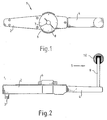
- the precision coefficient of friction meter 1 has on its load arm 2 an engagement element 3 for the adjustment of the tapered roller inner ring to the tapered roller outer ring and on its power arm 4 a crank 5 for initiating a slow rotational movement.
- the crank 5, which is firmly connected to the end of the power arm 4, consists of a crank rod 10 and a handle 9, for example a ball head, which is rotatably arranged on it.
- a rotatable scale 6 with a pointer 7 and a drag pointer 8.
Abstract
Description
Die Erfindung bezieht sich auf einen Drehmomentenschlüssel mit Skalenmeßuhr und Schleppzeiger. Drehmomentenschlüssel, insbesondere auch mit Schleppzeiger sind hinreichend bekannt, siehe hierzu z.B. DE-PS 709 212. Es sind auch Meßuhren bzw. -Vorrichtungen mit Schleppzeigern zur Messung von Drehmomenten für verschiedene Einsatzzwecke bekannt, siehe hierzu Prospekt der Firma Stenzel: "Waters Drehmoment-Meßuhren", 1975; Skornjakow: "Geräte zur Messung von Drehmomenten" in "Feingerätetechnik", 5. Jahrgang, 1956, Heft 4, Seite 174 bis 175.The invention relates to a torque wrench with dial gauge and drag pointer. Torque wrenches, especially those with a pointer, are well known, see e.g. DE-PS 709 212. There are also dial gauges or devices with drag pointers for measuring torque for various purposes, see the prospectus of the Stenzel company: "Waters Torque Dial Gauges", 1975; Skornjakow: "Devices for measuring torque" in "Fine equipment technology", 5th year, 1956,
Im Kraftfahrzeugbau werden beim Kraftfahrzeug-Ritzel und -Differential oder ähnlichen Stellen vorgespannte Lager vorgesehen. Eine genaue, konstante und wirksame Methode der Lagereinstellung wird durch die Benutzung des Lagereibmomentes erzielt. Mit der DE-AS 15 25 256 ist der Hinweis auf ein derartiges Verfahren zur Ermittlung des einer gewünschten Vorspannkraft entsprechenden Reibmomentes einer Wälzlageranordnung gegeben. Das Verfahren ist unabhängig davon anwendbar, ob Lagerluft oder Vorspannung als endgültige Einstellung gewünscht wird. Der Wert für das Lagerreibmoment ist ein Maß für die Vorspannung.In motor vehicle construction, preloaded bearings are provided in the motor vehicle pinion and differential or similar places. A precise, constant and effective method of bearing adjustment is achieved by using the bearing friction torque. DE-AS 15 25 256 provides an indication of such a method for determining the frictional torque of a rolling bearing arrangement corresponding to a desired preload force. The method can be used regardless of whether internal clearance or preload is required as the final setting. The value for the bearing friction torque is a measure of the preload.
Aufgabe der Erfindung ist es daher, eine preisgünstige, genaue und einfach handhabbare Vorrichtung zur Einstellung von Kegelrollenlagern anzugeben.The object of the invention is therefore to provide an inexpensive, accurate and easy-to-use device for adjusting tapered roller bearings.
Diese Aufgabe wird durch die im Anspruch 1 angegebene Verwendung eines Drehmomentschlüssels gelöst.This object is achieved by the use of a torque wrench specified in claim 1.
Die beanspruchte Verwendung eines Drehmomentenschlüssels als Reibwertmesser gestattet nun eine wesentliche Vergrößerung des Meßbereiches, eine große Genauigkeit wie auch eine bessere Ablesbarkeit durch den Schleppzeiger. Hervorzuheben ist, daß auf ein handelsübliches Instrument zurückgegriffen werden kann, dem nunmehr ein doppeltes Einsatzgebiet zugeordnet werden kann (2. Indikation), wodurch neben den vorbeschriebenen technischen Vorteilen auch Kosten reduziert werden und Werkzeughaltung reduziert wird.The claimed use of a torque wrench as a coefficient of friction now permits a substantial enlargement of the measuring range, great accuracy as well as better readability by the drag pointer. It should be emphasized that a commercially available instrument can be used, which can now be assigned to a double area of application (2nd indication), which, in addition to the technical advantages described above, also reduces costs and tool holding.
Am Kraftarm ist eine Kurbel angeordnet. Dies veranlaßt den Monteur zu der erforderlichen schleppenden Drehbewegung, so daß ein unkontrolliertes Losreißmoment vermieden wird.A crank is arranged on the power arm. This causes the fitter to carry out the required sluggish rotary movement, so that an uncontrolled tearing torque is avoided.
Die Kurbel weist eine Griff auf, der gegenüber der kraftarmfesten Kurbelstange drehbar ist. Solcherart wird ein verbessertes Feingefühl für die erforderliche schleppende Drehbewegung erzielt.The crank has a handle that is rotatable relative to the crank arm that is fixed to the power arm. In this way, an improved sensitivity to the required slow rotational movement is achieved.
Die Erfindung ist in einem Ausführungsbeispiel dargestellt.The invention is shown in one embodiment.
Es zeigen:
- Fig. 1
- einen Präzisions-Reibwertmesser in der Draufsicht,
- Fig. 2
- einen Präzisions-Reibwertmesser in der Seitenansicht.
- Fig. 1
- a precision friction meter in top view,
- Fig. 2
- a precision friction meter in side view.
Der Präzisions-Reibwertmesser 1 weist an seinem Lastarm 2 ein Eingriffselement 3 für die Anstellung von Kegelrollen-Innenring zu Kegelrollen-Außenring auf und an seinem Kraftarm 4 ein Kurbel 5 zur Einleitung einer schleppenden Drehbewegung. Die fest mit dem Ende des Kraftarmes 4 verbundene Kurbel 5 besteht aus einer Kurbelstange 10 und einem an ihr drehbar angeordneten Griff 9, z.B. einem Kugelkopf. Ungefähr in der Mitte des Reibwertmessers befindet sich eine drehbare Skala 6 mit einem Zeiger 7 und einem Schleppzeiger 8.The precision coefficient of friction meter 1 has on its
Claims (1)
- Use of a torque spanner (1) with a direct-reading dial gauge (6) and a settable pointer (8) as precision friction-value gauge for adjusting tapered roller bearings in axles and gearings, the engaging end (2) of the torque spanner (1) having an engaging member (3) for adjusting the inner ring of the tapered roller relative to the outer ring of the tapered roller, and the handle end (4) of the torque spanner (1) having a grip-type crank (5) which extends parallel to the axis of the engaging member (3).
Applications Claiming Priority (2)
| Application Number | Priority Date | Filing Date | Title |
|---|---|---|---|
| DE3905302A DE3905302C1 (en) | 1989-02-21 | 1989-02-21 | |
| DE3905302 | 1989-02-21 |
Publications (2)
| Publication Number | Publication Date |
|---|---|
| EP0384107A1 EP0384107A1 (en) | 1990-08-29 |
| EP0384107B1 true EP0384107B1 (en) | 1994-04-20 |
Family
ID=6374594
Family Applications (1)
| Application Number | Title | Priority Date | Filing Date |
|---|---|---|---|
| EP90100326A Expired - Lifetime EP0384107B1 (en) | 1989-02-21 | 1990-01-09 | Adjusting device for bearings |
Country Status (7)
| Country | Link |
|---|---|
| EP (1) | EP0384107B1 (en) |
| JP (1) | JPH02269578A (en) |
| AT (1) | ATE104582T1 (en) |
| DE (2) | DE3905302C1 (en) |
| DK (1) | DK0384107T3 (en) |
| ES (1) | ES2052074T3 (en) |
| NO (1) | NO900797L (en) |
Families Citing this family (1)
| Publication number | Priority date | Publication date | Assignee | Title |
|---|---|---|---|---|
| CN108098668A (en) * | 2017-11-29 | 2018-06-01 | 中国航发沈阳黎明航空发动机有限责任公司 | A kind of torque wrench measuring index selection method of equipped adapter |
Family Cites Families (4)
| Publication number | Priority date | Publication date | Assignee | Title |
|---|---|---|---|---|
| DE709212C (en) * | 1939-06-04 | 1941-08-09 | Bernhard Steinborn | Tension wrench with hydraulic clamping force display device |
| DE1108628B (en) * | 1956-02-04 | 1961-06-08 | Daimler Benz Ag | Device for adjusting axial pressure or axial and radial pressure roller bearings |
| US3318176A (en) * | 1965-10-21 | 1967-05-09 | Jr Herbert F Geier | Wrench having a pentagonal socket with threaded adjustment means |
| DE1525256B2 (en) * | 1965-12-08 | 1973-03-29 | Skf Kugellagerfabriken Gmbh, 8720 Schweinfurt | PROCEDURE FOR DETERMINING THE FRICTION MOMENT OF A ROLLER BEARING ARRANGEMENT, CORRESPONDING TO A DESIRED PRELOADING FORCE |
-
1989
- 1989-02-21 DE DE3905302A patent/DE3905302C1/de not_active Expired - Fee Related
-
1990
- 1990-01-09 ES ES90100326T patent/ES2052074T3/en not_active Expired - Lifetime
- 1990-01-09 DE DE59005397T patent/DE59005397D1/en not_active Expired - Fee Related
- 1990-01-09 EP EP90100326A patent/EP0384107B1/en not_active Expired - Lifetime
- 1990-01-09 DK DK90100326.9T patent/DK0384107T3/en active
- 1990-01-09 AT AT9090100326T patent/ATE104582T1/en active
- 1990-02-19 JP JP2036426A patent/JPH02269578A/en active Pending
- 1990-02-20 NO NO90900797A patent/NO900797L/en unknown
Also Published As
| Publication number | Publication date |
|---|---|
| DE59005397D1 (en) | 1994-05-26 |
| DE3905302C1 (en) | 1990-04-12 |
| NO900797L (en) | 1990-08-22 |
| ATE104582T1 (en) | 1994-05-15 |
| ES2052074T3 (en) | 1994-07-01 |
| NO900797D0 (en) | 1990-02-20 |
| EP0384107A1 (en) | 1990-08-29 |
| DK0384107T3 (en) | 1994-05-24 |
| JPH02269578A (en) | 1990-11-02 |
Similar Documents
| Publication | Publication Date | Title |
|---|---|---|
| DE2734182A1 (en) | DEVICE FOR MEASURING STEERING TORQUE AND STEERING ANGLE IN VEHICLES | |
| EP0384107B1 (en) | Adjusting device for bearings | |
| EP0162992B1 (en) | Single-handle torque wrench | |
| CH635680A5 (en) | BRAKE TEST FOR MOTOR VEHICLES. | |
| DE1930769B2 (en) | DEVICE FOR MEASURING THE RADIUS OF CURVATURE OF DISCS | |
| EP0075779B1 (en) | Brake testing stand | |
| DE2651636A1 (en) | Torque wrench with slide potentiometer to measure torque - has bending rod connected to potentiometer and running parallel to wrench shaft | |
| DE849308C (en) | Measuring device for height measurements on flat surfaces | |
| DE52767C (en) | Dimension and drawing angles, particularly useful for recording the development figures of conical bodies | |
| DE146966C (en) | ||
| DE4344565C1 (en) | Device for measuring loads | |
| DE313087C (en) | ||
| DE182963C (en) | ||
| DE377687C (en) | Reading device for measuring instruments | |
| DE2150364C (en) | Measuring and display device | |
| DE1100300B (en) | Length measuring device | |
| DE748696C (en) | Display profile instrument with a particularly long scale and deflection on both sides for remote speed measuring systems in both directions of rotation | |
| DE7635688U1 (en) | TORQUE TESTING DEVICE FOR TOOLS, ESPECIALLY WRENCHES | |
| CH637467A5 (en) | Portable angle-measuring or monitoring instrument | |
| DD153628A1 (en) | INCREMENTAL LENGTH MEASUREMENT DEVICE | |
| DE1548237A1 (en) | Device for length measurement, especially for inside and outside measurements | |
| DE2148962A1 (en) | CONTACT MEASURING DEVICE | |
| DD269216A1 (en) | DIRECTION INDICATORS TILTING KNIVES FOR PRESSURE BONDING EQUIPMENT | |
| DE1708431U (en) | MEASURING DEVICE FOR RUNNING MEASUREMENT OF DISTANCES. | |
| CH400612A (en) | Spring tester |
Legal Events
| Date | Code | Title | Description |
|---|---|---|---|
| PUAI | Public reference made under article 153(3) epc to a published international application that has entered the european phase |
Free format text: ORIGINAL CODE: 0009012 |
|
| AK | Designated contracting states |
Kind code of ref document: A1 Designated state(s): AT BE CH DE DK ES FR GB IT LI NL SE |
|
| 17P | Request for examination filed |
Effective date: 19900914 |
|
| 17Q | First examination report despatched |
Effective date: 19920519 |
|
| ITF | It: translation for a ep patent filed |
Owner name: DE DOMINICIS & MAYER S. |
|
| GRAA | (expected) grant |
Free format text: ORIGINAL CODE: 0009210 |
|
| AK | Designated contracting states |
Kind code of ref document: B1 Designated state(s): AT BE CH DE DK ES FR GB IT LI NL SE |
|
| REF | Corresponds to: |
Ref document number: 104582 Country of ref document: AT Date of ref document: 19940515 Kind code of ref document: T |
|
| REG | Reference to a national code |
Ref country code: DK Ref legal event code: T3 |
|
| REF | Corresponds to: |
Ref document number: 59005397 Country of ref document: DE Date of ref document: 19940526 |
|
| ET | Fr: translation filed | ||
| GBT | Gb: translation of ep patent filed (gb section 77(6)(a)/1977) |
Effective date: 19940504 |
|
| REG | Reference to a national code |
Ref country code: ES Ref legal event code: FG2A Ref document number: 2052074 Country of ref document: ES Kind code of ref document: T3 |
|
| PGFP | Annual fee paid to national office [announced via postgrant information from national office to epo] |
Ref country code: CH Payment date: 19941124 Year of fee payment: 6 |
|
| PGFP | Annual fee paid to national office [announced via postgrant information from national office to epo] |
Ref country code: SE Payment date: 19941130 Year of fee payment: 6 |
|
| PGFP | Annual fee paid to national office [announced via postgrant information from national office to epo] |
Ref country code: BE Payment date: 19941215 Year of fee payment: 6 |
|
| PGFP | Annual fee paid to national office [announced via postgrant information from national office to epo] |
Ref country code: GB Payment date: 19950103 Year of fee payment: 6 |
|
| PGFP | Annual fee paid to national office [announced via postgrant information from national office to epo] |
Ref country code: DK Payment date: 19950104 Year of fee payment: 6 |
|
| PGFP | Annual fee paid to national office [announced via postgrant information from national office to epo] |
Ref country code: ES Payment date: 19950105 Year of fee payment: 6 Ref country code: AT Payment date: 19950105 Year of fee payment: 6 |
|
| PGFP | Annual fee paid to national office [announced via postgrant information from national office to epo] |
Ref country code: DE Payment date: 19950118 Year of fee payment: 6 |
|
| EAL | Se: european patent in force in sweden |
Ref document number: 90100326.9 |
|
| PGFP | Annual fee paid to national office [announced via postgrant information from national office to epo] |
Ref country code: NL Payment date: 19950131 Year of fee payment: 6 Ref country code: FR Payment date: 19950131 Year of fee payment: 6 |
|
| PLBE | No opposition filed within time limit |
Free format text: ORIGINAL CODE: 0009261 |
|
| STAA | Information on the status of an ep patent application or granted ep patent |
Free format text: STATUS: NO OPPOSITION FILED WITHIN TIME LIMIT |
|
| 26N | No opposition filed | ||
| PG25 | Lapsed in a contracting state [announced via postgrant information from national office to epo] |
Ref country code: GB Effective date: 19960109 Ref country code: DK Effective date: 19960109 Ref country code: AT Effective date: 19960109 |
|
| REG | Reference to a national code |
Ref country code: DK Ref legal event code: EBP |
|
| PG25 | Lapsed in a contracting state [announced via postgrant information from national office to epo] |
Ref country code: SE Effective date: 19960110 Ref country code: ES Free format text: LAPSE BECAUSE OF NON-PAYMENT OF DUE FEES Effective date: 19960110 |
|
| PG25 | Lapsed in a contracting state [announced via postgrant information from national office to epo] |
Ref country code: LI Effective date: 19960131 Ref country code: CH Effective date: 19960131 Ref country code: BE Effective date: 19960131 |
|
| BERE | Be: lapsed |
Owner name: MAN NUTZFAHRZEUGE A.G. Effective date: 19960131 |
|
| PG25 | Lapsed in a contracting state [announced via postgrant information from national office to epo] |
Ref country code: NL Effective date: 19960801 |
|
| GBPC | Gb: european patent ceased through non-payment of renewal fee |
Effective date: 19960109 |
|
| REG | Reference to a national code |
Ref country code: CH Ref legal event code: PL |
|
| PG25 | Lapsed in a contracting state [announced via postgrant information from national office to epo] |
Ref country code: FR Effective date: 19960930 |
|
| NLV4 | Nl: lapsed or anulled due to non-payment of the annual fee |
Effective date: 19960801 |
|
| PG25 | Lapsed in a contracting state [announced via postgrant information from national office to epo] |
Ref country code: DE Effective date: 19961001 |
|
| EUG | Se: european patent has lapsed |
Ref document number: 90100326.9 |
|
| REG | Reference to a national code |
Ref country code: FR Ref legal event code: ST |
|
| REG | Reference to a national code |
Ref country code: ES Ref legal event code: FD2A Effective date: 19990503 |
|
| PG25 | Lapsed in a contracting state [announced via postgrant information from national office to epo] |
Ref country code: IT Free format text: LAPSE BECAUSE OF NON-PAYMENT OF DUE FEES;WARNING: LAPSES OF ITALIAN PATENTS WITH EFFECTIVE DATE BEFORE 2007 MAY HAVE OCCURRED AT ANY TIME BEFORE 2007. THE CORRECT EFFECTIVE DATE MAY BE DIFFERENT FROM THE ONE RECORDED. Effective date: 20050109 |