EP0384085B1 - Vorrichtung zur Halterung eines Tanks für Wärmeaustauscher - Google Patents
Vorrichtung zur Halterung eines Tanks für Wärmeaustauscher Download PDFInfo
- Publication number
- EP0384085B1 EP0384085B1 EP89313716A EP89313716A EP0384085B1 EP 0384085 B1 EP0384085 B1 EP 0384085B1 EP 89313716 A EP89313716 A EP 89313716A EP 89313716 A EP89313716 A EP 89313716A EP 0384085 B1 EP0384085 B1 EP 0384085B1
- Authority
- EP
- European Patent Office
- Prior art keywords
- strip
- hook
- heat exchanger
- flange
- apertures
- Prior art date
- Legal status (The legal status is an assumption and is not a legal conclusion. Google has not performed a legal analysis and makes no representation as to the accuracy of the status listed.)
- Expired - Lifetime
Links
- 230000015572 biosynthetic process Effects 0.000 claims description 30
- 238000005755 formation reaction Methods 0.000 claims description 30
- 210000001331 nose Anatomy 0.000 claims description 19
- 230000002093 peripheral effect Effects 0.000 claims description 10
- 238000010276 construction Methods 0.000 description 10
- 238000010494 dissociation reaction Methods 0.000 description 8
- 230000005593 dissociations Effects 0.000 description 8
- 238000007789 sealing Methods 0.000 description 5
- 239000000463 material Substances 0.000 description 3
- 239000002184 metal Substances 0.000 description 3
- 229910052751 metal Inorganic materials 0.000 description 3
- 238000007906 compression Methods 0.000 description 2
- 239000007788 liquid Substances 0.000 description 2
- 229910001369 Brass Inorganic materials 0.000 description 1
- WYTGDNHDOZPMIW-RCBQFDQVSA-N alstonine Natural products C1=CC2=C3C=CC=CC3=NC2=C2N1C[C@H]1[C@H](C)OC=C(C(=O)OC)[C@H]1C2 WYTGDNHDOZPMIW-RCBQFDQVSA-N 0.000 description 1
- 239000004411 aluminium Substances 0.000 description 1
- 229910052782 aluminium Inorganic materials 0.000 description 1
- XAGFODPZIPBFFR-UHFFFAOYSA-N aluminium Chemical compound [Al] XAGFODPZIPBFFR-UHFFFAOYSA-N 0.000 description 1
- 230000000903 blocking effect Effects 0.000 description 1
- 239000010951 brass Substances 0.000 description 1
- 230000001351 cycling effect Effects 0.000 description 1
- 239000000446 fuel Substances 0.000 description 1
- 238000009434 installation Methods 0.000 description 1
- 230000014759 maintenance of location Effects 0.000 description 1
Images


Classifications
-
- F—MECHANICAL ENGINEERING; LIGHTING; HEATING; WEAPONS; BLASTING
- F28—HEAT EXCHANGE IN GENERAL
- F28F—DETAILS OF HEAT-EXCHANGE AND HEAT-TRANSFER APPARATUS, OF GENERAL APPLICATION
- F28F9/00—Casings; Header boxes; Auxiliary supports for elements; Auxiliary members within casings
-
- F—MECHANICAL ENGINEERING; LIGHTING; HEATING; WEAPONS; BLASTING
- F28—HEAT EXCHANGE IN GENERAL
- F28F—DETAILS OF HEAT-EXCHANGE AND HEAT-TRANSFER APPARATUS, OF GENERAL APPLICATION
- F28F9/00—Casings; Header boxes; Auxiliary supports for elements; Auxiliary members within casings
- F28F9/02—Header boxes; End plates
- F28F9/0219—Arrangements for sealing end plates into casing or header box; Header box sub-elements
- F28F9/0224—Header boxes formed by sealing end plates into covers
- F28F9/0226—Header boxes formed by sealing end plates into covers with resilient gaskets
-
- F—MECHANICAL ENGINEERING; LIGHTING; HEATING; WEAPONS; BLASTING
- F28—HEAT EXCHANGE IN GENERAL
- F28F—DETAILS OF HEAT-EXCHANGE AND HEAT-TRANSFER APPARATUS, OF GENERAL APPLICATION
- F28F2275/00—Fastening; Joining
- F28F2275/08—Fastening; Joining by clamping or clipping
-
- Y—GENERAL TAGGING OF NEW TECHNOLOGICAL DEVELOPMENTS; GENERAL TAGGING OF CROSS-SECTIONAL TECHNOLOGIES SPANNING OVER SEVERAL SECTIONS OF THE IPC; TECHNICAL SUBJECTS COVERED BY FORMER USPC CROSS-REFERENCE ART COLLECTIONS [XRACs] AND DIGESTS
- Y10—TECHNICAL SUBJECTS COVERED BY FORMER USPC
- Y10T—TECHNICAL SUBJECTS COVERED BY FORMER US CLASSIFICATION
- Y10T403/00—Joints and connections
- Y10T403/70—Interfitted members
- Y10T403/7045—Interdigitated ends
Definitions
- each of the formations is hook-like with the hook-part of the hook-like formation lodged against a side of the upstanding flange oppositely of the strip.
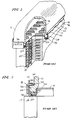
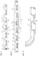
- Figs. 10 and 11 show still another embodiment of the invention.
- This embodiment also makes use of the resiliency of the seal 30.
- trapezoidal apertures 90 are utilized and have their major bases 92 downwardly and their minor bases 94 remote from the surface 28.
- the hook-like formations are T-shaped as shown at 96 and have oppositely directed noses 98 extending from the base of the finger 100.
Landscapes
- Engineering & Computer Science (AREA)
- Physics & Mathematics (AREA)
- Thermal Sciences (AREA)
- Mechanical Engineering (AREA)
- General Engineering & Computer Science (AREA)
- Heat-Exchange Devices With Radiators And Conduit Assemblies (AREA)
- Filling Or Discharging Of Gas Storage Vessels (AREA)
- Details Of Heat-Exchange And Heat-Transfer (AREA)
Claims (15)
- Wärmetauscher umfassend eine Kopfplatte (14) mit einer dichtungsaufnehmenden Umfangsrille (22), einer elastischen, in der Rille (22) angeordneten Dichtung (30), mit einem aufgerichteten Flansch (26), der die Rille (22) umgibt, mit einer ausgerichteten Reihe von Öffnungen (36; 70; 80; 90) in dem Flansch (26) oberhalb des Bodens der Rille (22), mit einem Tank (10), der einen umfangsmäßig nach außen gerichteten und in der Rille (22) angeordneten Flansch (11) aufweist, und der eine erste Fläche (32) aufweist, die mit der Dichtung (30) abdichtet und diese und eine gegenüberliegende Fläche (34), die nominal mit der Reihe von Öffnungen (36; 70; 80; 90) ausgerichtet ist, zusammendrückt, und mit einem Tankflansch-Halter (50), der einen langgestreckten Streifen (52; 38) mit einer Mehrzahl von Formationen (54; 96) umfaßt, die auf der Seite des aufgerichteten Flansches (26) gegenüber der Rille (22) angeordnet sind, wobei sich die Formationen (54; 96) durch die Öffnungen (36; 70; 80; 90) erstrecken, gegenüber des Streifens (52; 38) in über dem Tankflansch (11) liegender Beziehung, um in die gegenüberliegende Fläche (34) des Tankflansches (11) einzugreifen, dadurch gekennzeichnet, daß jede der Formationen (54; 96) hakenartig ausgebildet ist, wobei der Hakenteil (60; 98) der hakenartigen Formation (54; 96) an einer Seite des aufgerichteten Flansches (26) gegenüber dem Streifen (52; 38) anliegt.
- Wärmetauscher gemäß Anspruch 1, bei dem jede der hakenartigen Formationen (54; 96) eine Nase (60; 98) umfaßt, und bei dem sich jede der Nasen (60; 98) in der Erstreckungsrichtung des Streifens (52; 38) erstreckt.
- Wärmetauscher gemäß Anspruch 1 oder 2, der ferner einen Clip (66) in einer (36) der genannten Öffnungen (36) umfaßt, der an der betreffenden hakenartigen Formation (54) anliegt, um eine merkliche Bewegung derselben in der genannten einen Öffnung (36) zu verhindern und um so eine merkliche Bewegung des Streifens (52) in bezug auf den aufgerichteten Flansch (26) zu verhindern.
- Wärmetauscher gemäß Anspruch 1 oder 2, bei dem die Öffnungen (90) an ihrer von der Rille (22) am weitesten entfernten Lage enger als an ihrer der Rille (22) nächstgelegenen Lage sind.
- Wärmetauscher gemäß Anspruch 4, bei dem die Ausdehnung jeder hakenartigen Formation (96) in der Richtung der Erstreckung des Streifens (38) geringer ist als die Ausdehnung der entsprechenden Öffnung (90) an der genannten nächstgelegenen Lage und größer ist als die Ausdehnung der entsprechenden Öffnung (90) an der genannten entferntesten Lage.
- Wärmetauscher gemäß Anspruch 4 oder 5, bei dem die hakenartigen Formationen (96) T-förmig sind.
- Wärmetauscher gemäß Anspruch 1, bei dem die hakenartigen Formationen (54; 96) durch eine Mehrzahl von Fingern (54; 100) gebildet sind, die in hakenartigen Nasen (60; 98) enden, die auf der Seite des aufgerichteten Flansches (26) gegenüber der Rille (22) liegen, wobei sich die Finger (54; 100) durch die Öffnungen (30; 70; 80; 90) derart erstrecken, daß die Nasen (60; 98) an dem aufgerichteten Flansch (26) gegenüber dem Streifen (52; 38) in übereinanderliegender Beziehung in bezug auf den Tankflansch (11) und im Eingriff mit der gegenüberliegenden Fläche des Tankflansches (11) anliegen.
- Wärmetauscher gemäß Anspruch 7, bei dem die Öffnungen (70; 90) in von der gegenüberliegenden Fläche (34) des aufgerichteten Flansches (26) entfernter Lage relativ eng sind und nahe der Fläche (34) relativ weit sind, und wobei die hakenartigen Nasen (60; 98) so bemessen sind, daß sie in die Öffnungen (70; 90) und aus diesen heraus in der Nähe der Fläche (34) beweglich sind, jedoch in den Öffnungen (70; 90) gefangen sind, wenn sie von der Fläche (34) entfernt sind, und wobei die elastische Dichtung (30) den Tank (10) von der Fläche (34) derart wegdrängt, daß der Tankflansch (11) die Nasen (60; 98) in den engeren Teil der zugehörigen Öffnung (70; 90) drängt.
- Wärmetauscher gemäß Anspruch 8, bei dem sich die Nasen (98) von beiden Seiten des Fingers (100) in gegenüberliegende Richtungen erstrecken.
- Wärmetauscher gemäß Anspruch 9, bei dem die Öffnungen (90) trapezförmig ausgebildet sind.
- Wärmetauscher gemäß Anspruch 8, bei dem die Öffnungen (70) L-förmig ausgebildet sind.
- Wärmetauscher gemäß Anspruch 1, der ferner Mittel (60) auf dem Streifen (38; 52) umfaßt, um zu vermeiden, daß irgendeine der hakenartigen Formationen (54) an dem aufgerichteten Flansch (26) anliegt, es sei denn, daß alle der hakenartigen Formationen (54) an dem aufgerichteten Flansch (26) anliegen.
- Wärmetauscher gemäß Anspruch 12, bei dem die hakenartigen Formationen (54) sich alle in derselben Erstreckungsrichtung des Streifens (38; 52) öffnen, und bei dem die Mittel (60) zur Vermeidung Nasen (60) auf den hakenartigen Formationen (54) umfassen.
- Wärmetauscher gemäß Anspruch 13, bei dem die hakenartigen Formationen (54) durch Aussparungen (62) an Fingern (54) gebildet sind, die sich im wesentlichen quer von dem Streifen (38; 52) erstrecken.
- Wärmetauscher gemäß Anspruch 14, bei dem die Öffnungen (36; 70; 80) Schlitze (36; 70; 80) sind, die sich in der Erstreckungsrichtung des Streifens (52; 38) erstrecken und eine Länge aufweisen, die etwas größer als die Breite der Finger (54) an den Nasen (60) ist.
Priority Applications (1)
| Application Number | Priority Date | Filing Date | Title |
|---|---|---|---|
| AT89313716T ATE102703T1 (de) | 1989-02-23 | 1989-12-29 | Vorrichtung zur halterung eines tanks fuer waermeaustauscher. |
Applications Claiming Priority (2)
| Application Number | Priority Date | Filing Date | Title |
|---|---|---|---|
| US314157 | 1989-02-23 | ||
| US07/314,157 US4899815A (en) | 1989-02-23 | 1989-02-23 | Tank retaining strip for heat exchangers |
Publications (2)
| Publication Number | Publication Date |
|---|---|
| EP0384085A1 EP0384085A1 (de) | 1990-08-29 |
| EP0384085B1 true EP0384085B1 (de) | 1994-03-09 |
Family
ID=23218810
Family Applications (1)
| Application Number | Title | Priority Date | Filing Date |
|---|---|---|---|
| EP89313716A Expired - Lifetime EP0384085B1 (de) | 1989-02-23 | 1989-12-29 | Vorrichtung zur Halterung eines Tanks für Wärmeaustauscher |
Country Status (12)
| Country | Link |
|---|---|
| US (1) | US4899815A (de) |
| EP (1) | EP0384085B1 (de) |
| JP (1) | JP2754075B2 (de) |
| KR (2) | KR900013280A (de) |
| AR (1) | AR244878A1 (de) |
| AT (1) | ATE102703T1 (de) |
| AU (1) | AU612310B2 (de) |
| BR (1) | BR9000529A (de) |
| CA (1) | CA2006864C (de) |
| DE (1) | DE68913718T2 (de) |
| ES (1) | ES2052035T3 (de) |
| MX (1) | MX165311B (de) |
Families Citing this family (14)
| Publication number | Priority date | Publication date | Assignee | Title |
|---|---|---|---|---|
| DE4313141C2 (de) * | 1993-04-22 | 1995-04-13 | Voith Gmbh J M | Flanschmitnehmer für ein Kardangelenk |
| FR2732454B1 (fr) * | 1995-03-27 | 1997-05-09 | Valeo Thermique Moteur Sa | Echangeur de chaleur, notamment pour vehicule automobile |
| FR2735857B1 (fr) * | 1995-06-20 | 1997-08-01 | Valeo Climatisation | Echangeur de chaleur, notamment pour vehicule automobile |
| FR2742530B1 (fr) * | 1995-12-13 | 1998-01-30 | Valeo Thermique Moteur Sa | Dispositif et procede d'assemblage d'une plaque collectrice et d'une boite a eau d'echangeur de chaleur |
| DE19935688B4 (de) * | 1999-07-29 | 2004-07-01 | Behr Gmbh & Co. | Wärmeübertrager, insbesondere für Kraftfahrzeuge |
| US6675883B1 (en) * | 2002-07-08 | 2004-01-13 | Modine Manufacturing Company | Manifold for heat exchanger |
| DE10250441A1 (de) * | 2002-10-30 | 2004-05-13 | Modine Manufacturing Co., Racine | Wärmetauscher mit einer Dichtung |
| DE102014204272A1 (de) * | 2013-04-25 | 2014-10-30 | MAHLE Behr GmbH & Co. KG | Wärmeübertrager |
| DE102013225326A1 (de) * | 2013-12-09 | 2015-06-11 | MAHLE Behr GmbH & Co. KG | Wärmeübertrager |
| US10337801B2 (en) * | 2013-12-20 | 2019-07-02 | Modine Manufacturing Company | Heat exchanger for cooling a flow of charge air, and method of assembling the same |
| DE102014219210A1 (de) * | 2014-09-22 | 2016-03-24 | Mahle International Gmbh | Wärmeübertrager |
| US10156368B2 (en) * | 2015-09-25 | 2018-12-18 | Trane Air Conditioning Systems (China) Co., Ltd. | Fixing device for heat exchanger |
| US10527364B2 (en) * | 2017-03-03 | 2020-01-07 | Enterex America LLC | Heat exchanger manifold with header groove reinforcement member |
| WO2020166903A1 (ko) * | 2019-02-11 | 2020-08-20 | 한온시스템 주식회사 | 쿨링모듈 |
Family Cites Families (16)
| Publication number | Priority date | Publication date | Assignee | Title |
|---|---|---|---|---|
| US3352584A (en) * | 1964-12-16 | 1967-11-14 | Redirack Ind Ltd | Locking pin device for pallet rack |
| DE2703528C3 (de) * | 1977-01-28 | 1982-03-11 | Kühlerfabrik Längerer & Reich, 7024 Filderstadt | Wasserkühler, insbesondere für eine Brennkraftmaschine |
| JPS5923991Y2 (ja) * | 1979-03-13 | 1984-07-16 | 日本ラヂエーター株式会社 | 熱交換器 |
| US4287994A (en) * | 1979-11-02 | 1981-09-08 | Unarco Industries, Inc. | Wedgable storage rack |
| FR2469686A1 (fr) * | 1979-11-12 | 1981-05-22 | Chausson Usines Sa | Echangeur de chaleur comportant un faisceau de tubes debouchant dans des plaques collectrices reliees mecaniquement a des boites a eau |
| US4351390A (en) * | 1980-02-11 | 1982-09-28 | Borg-Warner Corporation | Retaining clips for gasketed tanks on heat exchangers |
| JPS587092U (ja) * | 1981-07-02 | 1983-01-18 | 株式会社デンソー | 熱交換器 |
| US4406374A (en) * | 1981-08-12 | 1983-09-27 | Myco, Inc. | Locking device for display rack |
| JPS5877288U (ja) * | 1981-11-13 | 1983-05-25 | カルソニックカンセイ株式会社 | 自動車用空気調和装置のヒ−タコア |
| US4485867A (en) * | 1982-02-08 | 1984-12-04 | Ex-Cell-O Corporation | Heat exchanger |
| SU1052834A1 (ru) * | 1982-07-22 | 1983-11-07 | Производственное Объединение "Радиатор" | Бачок радиатора |
| SE437648B (sv) * | 1983-04-15 | 1985-03-11 | Electrolux Const Ab | Anordning for att lasa en balk vid en stolpe, exv vid ett pallstell |
| FR2550328B1 (fr) * | 1983-08-04 | 1989-01-13 | Chausson Usines Sa | Dispositif de liaison entre une plaque collectrice et une boite a eau d'un echangeur de chaleur et procede pour sa mise en oeuvre |
| NL8303966A (nl) * | 1983-11-17 | 1985-06-17 | Nrf Holding | Radiateur. |
| US4546823A (en) * | 1985-02-11 | 1985-10-15 | Mccord Heat Transfer Corporation | Solderless radiator |
| US4682672A (en) * | 1986-04-21 | 1987-07-28 | Ford Motor Company | Snap-on oil pan |
-
1989
- 1989-02-23 US US07/314,157 patent/US4899815A/en not_active Expired - Fee Related
- 1989-12-28 CA CA002006864A patent/CA2006864C/en not_active Expired - Fee Related
- 1989-12-29 AT AT89313716T patent/ATE102703T1/de not_active IP Right Cessation
- 1989-12-29 EP EP89313716A patent/EP0384085B1/de not_active Expired - Lifetime
- 1989-12-29 ES ES89313716T patent/ES2052035T3/es not_active Expired - Lifetime
- 1989-12-29 DE DE68913718T patent/DE68913718T2/de not_active Expired - Fee Related
-
1990
- 1990-01-08 AU AU47784/90A patent/AU612310B2/en not_active Ceased
- 1990-01-18 KR KR1019900000564A patent/KR900013280A/ko not_active Withdrawn
- 1990-01-26 MX MX019266A patent/MX165311B/es unknown
- 1990-02-07 BR BR909000529A patent/BR9000529A/pt not_active IP Right Cessation
- 1990-02-21 KR KR2019900001907U patent/KR0125082Y1/ko not_active Expired - Fee Related
- 1990-02-22 JP JP2039912A patent/JP2754075B2/ja not_active Expired - Lifetime
- 1990-02-23 AR AR90316241A patent/AR244878A1/es active
Also Published As
| Publication number | Publication date |
|---|---|
| AU4778490A (en) | 1990-08-30 |
| ES2052035T3 (es) | 1994-07-01 |
| DE68913718D1 (de) | 1994-04-14 |
| BR9000529A (pt) | 1991-01-15 |
| KR910015800U (ko) | 1991-09-25 |
| KR900013280A (ko) | 1990-09-05 |
| ATE102703T1 (de) | 1994-03-15 |
| AU612310B2 (en) | 1991-07-04 |
| DE68913718T2 (de) | 1994-06-23 |
| AR244878A1 (es) | 1993-11-30 |
| CA2006864C (en) | 1999-07-20 |
| JPH02267494A (ja) | 1990-11-01 |
| CA2006864A1 (en) | 1990-08-23 |
| MX165311B (es) | 1992-11-04 |
| JP2754075B2 (ja) | 1998-05-20 |
| EP0384085A1 (de) | 1990-08-29 |
| KR0125082Y1 (en) | 1998-11-02 |
| US4899815A (en) | 1990-02-13 |
Similar Documents
| Publication | Publication Date | Title |
|---|---|---|
| EP0384085B1 (de) | Vorrichtung zur Halterung eines Tanks für Wärmeaustauscher | |
| CA2052877C (en) | Double plate partition for a heat exchanger | |
| AU754417B2 (en) | Welded heat exchanger with grommet construction | |
| US5758721A (en) | Heat exchanger header plate, a method for making it, and a heat exchanger having such a header plate | |
| EP0845650A2 (de) | Wärmetauscher, der ohne Hartlöten zusammengesetzt wird, wobei ein Klebstoff verwendet wird zur Verbindung zwischen Rohrenden und einer Endplatte | |
| US20070131404A1 (en) | Heat exchanger | |
| CN109844441B (zh) | 具有带有保持夹的旁通密封件的换热器 | |
| EP0625679A1 (de) | Kühleinheit und Abflussbehälter für Klimaanlagen | |
| RU2225580C2 (ru) | Пластинчатый теплообменник и пластинчатый элемент для него | |
| US7237605B2 (en) | Heat exchanger | |
| EP1132706A2 (de) | Wärmetauscher | |
| JPH05118787A (ja) | 複数の管列を有する特に自動車に適する熱交換器 | |
| EP0745820A1 (de) | Endkammer für Wärmetauscher | |
| CN101111736B (zh) | 热交换器 | |
| US5111877A (en) | Multi-tube heat exchanger with mechanically interlocked tubes formed from mechanically interlocked plates | |
| EP0724128A1 (de) | Endkammer für Wärmetauscher und Verfahren zu seinem Zusammenbau | |
| JP2020526731A (ja) | 熱交換器 | |
| US5899267A (en) | Heat exchanger sealed tank and header assembly with gasket displacement prevention | |
| US7520319B2 (en) | Stacking-type, multi-flow, heat exchanger | |
| US6357513B1 (en) | Support for heat exchanger tubes | |
| US6182745B1 (en) | Heat exchanger with protected thin edges, especially for a motor vehicle | |
| US5404940A (en) | Tie bar clip construction for heat exchangers | |
| JPH0640684U (ja) | 熱交換器 | |
| JP3173830B2 (ja) | 熱交換器 | |
| JP2003130580A (ja) | 熱交換器のタンク組付け構造 |
Legal Events
| Date | Code | Title | Description |
|---|---|---|---|
| PUAI | Public reference made under article 153(3) epc to a published international application that has entered the european phase |
Free format text: ORIGINAL CODE: 0009012 |
|
| AK | Designated contracting states |
Kind code of ref document: A1 Designated state(s): AT DE ES FR GB IT NL SE |
|
| 17P | Request for examination filed |
Effective date: 19901003 |
|
| 17Q | First examination report despatched |
Effective date: 19910325 |
|
| GRAA | (expected) grant |
Free format text: ORIGINAL CODE: 0009210 |
|
| AK | Designated contracting states |
Kind code of ref document: B1 Designated state(s): AT DE ES FR GB IT NL SE |
|
| ITF | It: translation for a ep patent filed | ||
| REF | Corresponds to: |
Ref document number: 102703 Country of ref document: AT Date of ref document: 19940315 Kind code of ref document: T |
|
| REF | Corresponds to: |
Ref document number: 68913718 Country of ref document: DE Date of ref document: 19940414 |
|
| REG | Reference to a national code |
Ref country code: ES Ref legal event code: FG2A Ref document number: 2052035 Country of ref document: ES Kind code of ref document: T3 |
|
| ET | Fr: translation filed | ||
| PLBE | No opposition filed within time limit |
Free format text: ORIGINAL CODE: 0009261 |
|
| STAA | Information on the status of an ep patent application or granted ep patent |
Free format text: STATUS: NO OPPOSITION FILED WITHIN TIME LIMIT |
|
| EAL | Se: european patent in force in sweden |
Ref document number: 89313716.6 |
|
| 26N | No opposition filed | ||
| PGFP | Annual fee paid to national office [announced via postgrant information from national office to epo] |
Ref country code: NL Payment date: 20001130 Year of fee payment: 12 Ref country code: FR Payment date: 20001130 Year of fee payment: 12 |
|
| PGFP | Annual fee paid to national office [announced via postgrant information from national office to epo] |
Ref country code: SE Payment date: 20001201 Year of fee payment: 12 Ref country code: GB Payment date: 20001201 Year of fee payment: 12 |
|
| PGFP | Annual fee paid to national office [announced via postgrant information from national office to epo] |
Ref country code: AT Payment date: 20001204 Year of fee payment: 12 |
|
| PGFP | Annual fee paid to national office [announced via postgrant information from national office to epo] |
Ref country code: DE Payment date: 20001211 Year of fee payment: 12 |
|
| PGFP | Annual fee paid to national office [announced via postgrant information from national office to epo] |
Ref country code: ES Payment date: 20010112 Year of fee payment: 12 |
|
| PG25 | Lapsed in a contracting state [announced via postgrant information from national office to epo] |
Ref country code: GB Free format text: LAPSE BECAUSE OF NON-PAYMENT OF DUE FEES Effective date: 20011229 Ref country code: AT Free format text: LAPSE BECAUSE OF NON-PAYMENT OF DUE FEES Effective date: 20011229 |
|
| PG25 | Lapsed in a contracting state [announced via postgrant information from national office to epo] |
Ref country code: SE Free format text: LAPSE BECAUSE OF NON-PAYMENT OF DUE FEES Effective date: 20011230 |
|
| REG | Reference to a national code |
Ref country code: GB Ref legal event code: IF02 |
|
| PG25 | Lapsed in a contracting state [announced via postgrant information from national office to epo] |
Ref country code: NL Free format text: LAPSE BECAUSE OF NON-PAYMENT OF DUE FEES Effective date: 20020701 |
|
| PG25 | Lapsed in a contracting state [announced via postgrant information from national office to epo] |
Ref country code: DE Free format text: LAPSE BECAUSE OF NON-PAYMENT OF DUE FEES Effective date: 20020702 |
|
| EUG | Se: european patent has lapsed |
Ref document number: 89313716.6 |
|
| GBPC | Gb: european patent ceased through non-payment of renewal fee |
Effective date: 20011229 |
|
| PG25 | Lapsed in a contracting state [announced via postgrant information from national office to epo] |
Ref country code: FR Free format text: LAPSE BECAUSE OF NON-PAYMENT OF DUE FEES Effective date: 20020830 |
|
| NLV4 | Nl: lapsed or anulled due to non-payment of the annual fee |
Effective date: 20020701 |
|
| REG | Reference to a national code |
Ref country code: FR Ref legal event code: ST |
|
| PG25 | Lapsed in a contracting state [announced via postgrant information from national office to epo] |
Ref country code: ES Free format text: LAPSE BECAUSE OF NON-PAYMENT OF DUE FEES Effective date: 20021230 |
|
| REG | Reference to a national code |
Ref country code: ES Ref legal event code: FD2A Effective date: 20030113 |
|
| PG25 | Lapsed in a contracting state [announced via postgrant information from national office to epo] |
Ref country code: IT Free format text: LAPSE BECAUSE OF NON-PAYMENT OF DUE FEES;WARNING: LAPSES OF ITALIAN PATENTS WITH EFFECTIVE DATE BEFORE 2007 MAY HAVE OCCURRED AT ANY TIME BEFORE 2007. THE CORRECT EFFECTIVE DATE MAY BE DIFFERENT FROM THE ONE RECORDED. Effective date: 20051229 |