EP0381530A2 - Electronic musical intrument - Google Patents
Electronic musical intrument Download PDFInfo
- Publication number
- EP0381530A2 EP0381530A2 EP90301143A EP90301143A EP0381530A2 EP 0381530 A2 EP0381530 A2 EP 0381530A2 EP 90301143 A EP90301143 A EP 90301143A EP 90301143 A EP90301143 A EP 90301143A EP 0381530 A2 EP0381530 A2 EP 0381530A2
- Authority
- EP
- European Patent Office
- Prior art keywords
- musical
- key
- tone
- tones
- manually operable
- Prior art date
- Legal status (The legal status is an assumption and is not a legal conclusion. Google has not performed a legal analysis and makes no representation as to the accuracy of the status listed.)
- Granted
Links
Images


Classifications
-
- G—PHYSICS
- G10—MUSICAL INSTRUMENTS; ACOUSTICS
- G10H—ELECTROPHONIC MUSICAL INSTRUMENTS; INSTRUMENTS IN WHICH THE TONES ARE GENERATED BY ELECTROMECHANICAL MEANS OR ELECTRONIC GENERATORS, OR IN WHICH THE TONES ARE SYNTHESISED FROM A DATA STORE
- G10H1/00—Details of electrophonic musical instruments
- G10H1/18—Selecting circuits
- G10H1/183—Channel-assigning means for polyphonic instruments
- G10H1/185—Channel-assigning means for polyphonic instruments associated with key multiplexing
- G10H1/186—Microprocessor-controlled keyboard and assigning means
-
- G—PHYSICS
- G10—MUSICAL INSTRUMENTS; ACOUSTICS
- G10H—ELECTROPHONIC MUSICAL INSTRUMENTS; INSTRUMENTS IN WHICH THE TONES ARE GENERATED BY ELECTROMECHANICAL MEANS OR ELECTRONIC GENERATORS, OR IN WHICH THE TONES ARE SYNTHESISED FROM A DATA STORE
- G10H1/00—Details of electrophonic musical instruments
- G10H1/02—Means for controlling the tone frequencies, e.g. attack or decay; Means for producing special musical effects, e.g. vibratos or glissandos
- G10H1/04—Means for controlling the tone frequencies, e.g. attack or decay; Means for producing special musical effects, e.g. vibratos or glissandos by additional modulation
- G10H1/053—Means for controlling the tone frequencies, e.g. attack or decay; Means for producing special musical effects, e.g. vibratos or glissandos by additional modulation during execution only
Definitions
- the invention relates to an electronic musical instrument in which musical tones of assigned pitches are generated in such a manner that the musical tones are controlled according to the operation of musical tone-controlling means, such as manually operable members.
- the timbre-selecting switches however have failed to provide a large range of timbre variation since only one musical tone is generated corresponding to one assigned musical pitch. Further, sudden change from a previous timbre to a new timbre makes it very difficult to produce a natural and smooth feeling as to alteration of timbres.
- the present invention was made to resolve those problems, and an object of the invention is to provide an electronic musical instrument in which several musical tones and/or several timbres can be produced in response to each assigned pitch and which affords a large variety of smooth timbre alterations with each tone or timbre being controlled properly.
- an electronic musical instrument comprises:
- control message-producing means automatically produces the musical tone-controlling messages which respectively correspond to the operations of said manually operable members.
- Each of the musical tone-controlling messages thus produced is then utilized in the musical tone-generating means to generate one of the musical tones with a controlled volume. Therefore, the plurality of said musical tones is generated by said generating means for each of the assigned pitches.
- the present invention may also be embodied in such a way that magnitudes of the musical tone-controlling messages for the musical tones which are to be generated are subjected to changes in the course of time and in response to speed or rapidity of the operation of aforementioned manually operable members.
- the magnitudes of the musical tone-controlling messages for musical tones to be generated are caused to change in the course of time when the manually operable members are operated into their ON-states whereas the magnitudes remain unchanged when said manually operable members are operated into their OFF-states.
- control message-producing means may produce the musical tone-controlling messages which are of such magnitudes that cause attenuation of the musical tones corresponding to some manually operable members other than those which are just newly operated, on the condition that said some manually operable members are in their unoperated states, or on the condition that said newly operated members are operated at a speed higher than a predetermined speed.
- control message-producing means may also produce the musical tone-controlling messages which are of such magnitudes that attenuates the musical tones corresponding to some manually operable members when these members are operated at a speed lower than the predetermined speed.
- an electronic musical instrument has a musical tone generator which is provided with tone-pitch assigning means 1, manually operable members (keys) 2, control message-producing means 3 connected to the members 2 to receive and process the signals therefrom and musical tone-generating means 4 connected to the tone pitch-assigning means 1 and controlled by the message-producing means 3.
- tone-controlling messages produced automatically by the message-producing means 3 correspond to the operation of the manually operable members 2.
- the electronic musical instrument in one embodiment of the invention comprises a keyboard 20 which is composed of 61 (sixty one) keys corresponding to C2-octave to C7-octave.
- 61 sixty one
- Four white keys included in a range from "C2" to "F2" constitute a second part 20A of the keyboard, with the remaining keys thereby constituting a first part 20B of the keyboard.
- a playing mode "1" which is the usual playing mode
- musical pitches are assigned to generated musical tones by means of both of the first and the second parts 20B and 20A of the keyboard.
- Key-depression and key-release speeds as well as key-pressures which are imparted to keys when they assign pitches to the generated musical tones are made use of to control said musical tones in this mode.
- a musical tone signal-generating circuit 29 generates, for each key-depression, four musical tones which are different from one another with respect to their pitches, timbres and volumes.
- the keys in the second part 20A produce control signals based on their key-depression or key-release states as well as based on speeds and pressures of such key operation, while pitch assignment and tone control are likewise conducted by the first part 20B as in the playing mode "1".
- the four white keys of "C2" to “F2" produce four control signals of different kinds so as to control the generated volume for each of the musical tones assigned by the keys in the first part 20B.
- operation of the four keys in the second part 20A of the keyboard is effective to perform control of four kinds as to the generated volume of each musical tone.
- a plurality of manually operable members (2) as manually operable means in the invention correspond to the four keys included in the second part 20A of keyboard. Operation of the manually operable members (2) corresponds to the operated states such as key-depression and key-release, the speeds and pressure thereof as to said second part 20A of the keyboard.
- Each of the abovementioned control signals is produced by integrating a first control signal component with a seecond control signal component, the first signal component being produced in accordance with the key-depression and key-release and the speeds thereof, while the second signal component is produced according to the pressure of depressed keys.
- Each of the first control signal components is produced to change itself asymptotically in the course of time with a given sharpness of change until it reaches a given ultimate or target level.
- the sharpness of change and the target level are provided by operation of the keys included in the second part 20A of the keyboard, in particular by the key-depression and key-release and the speeds thereof.
- the electronic musical instrument further comprises a key operation-detecting circuit 21 for sensing operation, i.e.
- a velocity detecting circuit 22 for sensing speeds of the key-depression and key-release and an after-touch-detecting circuit 23 for sensing pressures imparted to the keys on the keyboard 20 when they are depressed.
- Data which is produced as key information by these circuits is then fed to a microcomputer 24 through a bus 25, under control of said microcomputer.
- a control panel 26 also included in the musical instrument comprises setting members 26A to 26K and an indicator 26L which are shown in the drawing, as well as other manual members such as a timbre selection switch and a write-command switch which are not shown. Operations of these members also are detected under control of and fed to the microcomputer 24 so that data or information obtained thereby are indicated on the indicator 26L also under control of said microcomputer.
- Setting member 26A This is utilized to preset standard or target values for magnitudes of the first control signal components which are produced by key- depression (key-ON) of the keys on the second part 20A of the keyboard.
- Setting member 26B This is utilized to preset values of another type relative to magnitudes of the first control signal components which are produced according to the speed of key-depression of the keys in the second part 20A of the keyboard.
- Setting member 26C This is utilized to preset still other values relative to the sharpness of change in the course of time of the first control signal components which are produced when the keys in the second part 20A are depressed.
- Setting member 26D This is utilized to preset further values relative to the sharpness of change in the course of time of the first control signal components in order to cause the sharpness to depend upon the key-depression speeds of the keys in said second part 20A of the keyboard.
- Setting member 26E This is utilized to preset still further values relative to the sharpness of change in the course of time of the first control signal components which are produced when the depressed keys in the second part 20A are released.
- Setting member 26F This is utilized to preset yet further values relative to the sharpness of change in the course of time of the first control signal components in order to cause the sharpness to depend upon the key-release speeds of the keys in said second part 20A of the keyboard.
- Setting member 26G This member presets a threshold value "Vt" of key-depression speed which is utilized to cause the first control signal components to attenuate to "0" when the keys are depressed during a "hold” mode described later.
- Setting member 26H This member is used to preset values relevant to relationship between the pressure of depressed keys in second part 20A of the keyboard and the magnitudes of said second control signal components produced.
- the above setting members 26A to 26H are manipulated to select various relationships between the control signals and the operation of said part 20A of the keyboard during a presetting mode described below.
- Setting member (switch) 26I This is used to effect shift or changeover between the "hold” mode and another (non-hold) mode. the shift from the former to the latter and vice versa takes place whenever this setting member 26I is operated.
- the non-hold mode the four first control signal components are produced independently of one another, based on the key-depression and key-release and the speeds thereof of the four keys in second part 20A of the keyboard, respectively. Key-depression gives rise to the first control signal components, while key-release attenuates same. In the "hold” mode, however, any key-release itself cannot cause such an attenuation of the first control signal components but can do so only if the other key is depressed after one key has been released.
- Setting member (switch) 26J This is used to make selection between operation modes.
- the operation modes include a playing mode "1", a playing mode "2" and a presetting mode. Changeover from one mode to another take place step-wise in the order mentioned above every time the setting member 26J is operated. In a state wherein one of the playing modes "1" and “2" is currently effective, another pedal 27B also provides means to make a changeover among the modes.
- Setting member (switch) 26K This member is used to select one key among the four keys “C2" to "F2" in the second part 20A of the keyboard which is to be preset during the presetting mode. Each operation of this member 26K causes a sequential changeover from one key to the next.
- the setting of functions assigned to the keys in second part 20A of the keyboard is performed for respective keys by means of the setting members 26A to 26F and 26H, whereas setting by means of the setting member 26G is common to all the keys whichever thereof is adjusted as to its assigned function.
- a pedal group 27 comprises the pedals 27A and 27B.
- the pedal 27A serves for the changeover between the "hold” mode and the non-hold mode, the changeover occurring every time the pedal 27A is operated.
- the other pedal 27B is operated either during the playing modes "1" or during the playing mode “2" so as to effect changeover from the former to the latter or vice versa, also such changeover occurring each time the pedal 27B is operated. Operation of the pedal group 27 is detected by a pedal operation-detecting circuit 28 to produce pedal data which the microcomputer 24 controls to receive same through the bus 25.
- the microcomputer 24 comprises a central processing unit (CPU) 24A adapted to execute given programs, a read-only memory (ROM) 24B for storing the given programs, a random access memory (RAM) 24C for execution of the programs, and a timer circuit 24D for the counting of time lapse during said programs.
- the random access memory (RAM) 24B has areas defined therein which include a memory zone and a working zone. Musical tone data and other data are written into the memory zone, while the working zone comprises various registers, data tables and other small areas necessary to the function of the microcomputer 24.
- the RAM 24C is supported with a backup battery so that the data written therein is not degraded or last even in the event of a power failure.
- the programs referred to above are executed by the microcomputer 24 on the basis of the tone data, the key information (such as the states as to key-depression and key-release, the speeds thereof and the pressures imparted to the keys) and other data in order to control a musical tone signal-generating circuit 29.
- the musical tone signal-generating circuit 29 comprises 32 (thirty two) tone-generators.
- the microcomputer 24 selects four of the tone-generators for each depression of the keys which are operated for generation of musical tones (i.e., for assignment of musical pitches).
- the selected tone-generators receive, from the microcomputer, control signals designating pitches, timbres, volumes and other parameters which are used by said tone-generators to generate musical tone signals of four kinds.
- the musical tone signal-generating circuit 29 generates four different musical tone signals which are different from each other in respect of the musical pitch, the musical timbre, the volume and the other parameters.
- the microcomputer can deal with a plurality of key-depressions at the same time and cause the circuit to simultaneously generate 8 (eight) musical tone signals at maximum.
- the microcomputer 24 produces control signals of another kind when the keys for generation of musical tones are released; said control signals are supplied to such tone-generators that correspond to the released keys, thereby attenuating the musical tone signals.
- the musical tone signal-generating circuit 29 multiplies the control signals corresponding to key-depression of key-release of the keys for generation of musical tones by the musical volume-controlling signals which are supplied to said circuit 29 at regular intervals thereby to produce composite volume-controlling signals. Said signal-generating circuit 29 then generates final or synthetic musical tone signals based on the composite volume-controlling signals and the other control signals supplied by the microcomputer 24. The synthetic musical tone signals thus produced are then amplified in an amplifier 30, converted into audible sounds and output from a speaker 31.
- Fig. 3 shows memory areas assigned to the working zone in RAM 24C, the memory areas being used by the microcomputer 24 to execute such processings as needed in the invention.
- a register "Key Nos.” temporarily stores a key number designating a musical pitch of newly depressed or released key. The key-depression or key-release speed thereof is written in another register “Velocity”.
- Another register “RVt” stores the threshold value "Vt” for key-depression speeds in the "hold” mode.
- Denoted by "BP1" to "After-1” are memory areas which are utilized to produce control signals when the key "C2" in the second part 20A of the keyboard is operated.
- the register "BP1" is for memory of the target level of the first control signal component which has a magnitude changing in the course of time.
- a further register “K1” is provided to write therein a value corresponding to sharpness of the change in magnitude of said control signal component.
- a still further register "Current-1” temporarily stores a current value of the first control signal component
- a table “BPT1” stores relationships between key-depresssion speeds and the target magnitude levels of first control signal components produced by key-press. Data in the table “BPT1” is set by means of the setting members 26A and 26B in a manner as described later referring to Fig. 4.
- Another table “KONT1” stores relationships between the key-depression speeds and the values corresponding to sharpness of changes in the course of time of the produced first control signal component. Data in the table “KONT1” is set by means of the setting members 26C and 26D in a manner as described later referring to Fig. 4.
- a still further table “KOFFT1" stores relationships between the key-release speeds and the values corresponding to sharpness of changes in the course of time of the produced first control signal components.
- Data in the table “KOFFT1” is set by means of the setting members 26E and 26F in a manner as described later referring to Fig. 4.
- Another register “After-1” stores values which represent a relationship between the pressure of key-depression and the magnitude of produced second control signal component.
- Data in the table “After-1” is set by means of the setting member 26H.
- the suffix "1" carried by the memory area names "BP1" to "After-1” indicates that said areas are for the key "C2" in the second part 20A of the keyboard. There are similarly provided such memory areas as will be indicated by, for example, “BP2", “BP3” respectively for the three other white keys “D2", “E2” and “F2” constituting the "four” keys in the second part 20A.
- FIG. 4 Data contained in the abovementioned tables is illustrated in Fig. 4 wherein given along the abscissa are key-depression and key-release speeds. The stored values are given along the ordinate.
- a solid line in Fig. 4 shows the relationship between the key-depression and/or key-release speeds and said stored values.
- a symbol “Vc” denotes a medial value (i.e. centre value between a maximum and a minimum), another symbol “Lc” denoting a value stored corresponding to the medial value "Vc”.
- the aforementioned setting members preset the value "Lc" as well as the gradient of the inclined solid line.
- the aforedescribed setting members are classified into the followuing three groups, that is:
- the value “Lc” is set by the setting members included in the group “I”, and the gradient of an inclined solid line is set by means of the setting members included in the group “II”.
- the value “Lc” on the tables “BPT1" to “BPT4" is set by the setting member 26A, and the gradient of said inclined solid line is set by the setting member 26B. If said values thus set in such a procedure exceed a maximum or minimum value that can be received by relevant memory area or the like, then the maximum or minimum value is written thereinto in place of the actual values to be set.
- the setting members included in the groups "I" and “II” operated in this way make it possible to alter in various manners the relationships between the speeds of key-depression or key-release and the magnitudes of the produced first control signal components or the sharpness of thieir changes in the course of time.
- the same functions as above are applicable to all the other tables.
- each table carries thereon various values corresponding to key-depression or key-release speeds and capable of being altered owing to operation of the setting members.
- FIGs. 5 to 8 show processings relevant to the invention and executed by the microcomputer 24 when the playing mode "1" or "2" is selected.
- Step A1 The producing of the control signal components is carried out corresponding to the timer-interrupts which are given by a timer circuit 24D as shown in Fig. 5, the timer circuit 24D counting time lapse during this program.
- Step A1 a decision is made as to which of the playing modes "1" and "2" has been selected. If the former is the current mode, then the process goes to Step A7, while the process advances to Step A2 in a case where the playing mode "2" is on.
- Step A2 "1" is set to “n".
- the number “n” denotes the keys wherein “1” to “4" respectively denote the white keys "C2" to “F2”.
- Step A3 a decision is made as to whether “n” is "5" or not. If yes, then the process returns to the main routine processing, while the process will go to Step A4 in a case where "n” is not "5".
- each of current values of the first control signal components is subtracted from a corresponding target value thereof, the target values being those which are stored in the registers "BP[n], and the current values being those which are stored in the registers "Current[n]".
- each of differences thus obtained is then multiplied by a corresponding one of the values which represent the sharpness of change in the course of time of said first control signal components and which are stored in the registers "K[n]".
- the values stored in the registers "K[n]" are "1" or less but higher than "0").
- Step A5 a key-depression pressure of the key carrying the number "n” (shown as “Key pressure[n]” in Fig. 5) is multiplied by the corresponding value which is stored in the register "After[n]” and giving the relationship between said pressure and the second control signal component.
- a product i.e., the second control signal component itself
- a sum is the final musical volume-controlling signal and is supplied to the tone signal-generating circuit 29.
- Step A6 "1" is added to the current number "n".
- the suffix "n” in the above description denotes such memory area or key-depression pressure for the key which carries the number "n”, thus “BP[n]” means “BP1" when "n” is “1".
- step A7 a maximum which is found among the musical volume-controlling signals is supplied to the tone signal-generating circuit 29.
- Fig. 6 shows the first control signal components resulting from the just described processing. Time lapse is measured along the abscissa and magnitudes of the data stored in the registers "BP1" to "BP4" and in the registers "Current-1” to “Current-4" are measured along the ordinate. It is assumed that these data stored in all the registers referred to here have a value "L0" until the instant "T0". It will however be seen from Fig.
- new control signal components are produced to be output and to be of magnitudes which change in the course of time in the playing mode "2", while the control signal components are invariably set at the maximum value in playing mode "1".
- Step B1 a key number of the newly depressed key is written into the register "Key Nos.”, and its key-depression speed is written into the register "Velocity”.
- Step B2 a decision is made as to which of the playing modes "1" and "2" has been selected.
- Step B16 If the former is the current mode, then the process goes to Step B16, while the process advances to Step B3 in a case where the playing mode "2" is on.
- Step B3 A decision is made at Step B3 as to whether the newly depressed key is or is not one included in the second part 20A of the keyboard, based on the value currently carried by the register "Key Nos". If yes, then go to Step B4, but is no, then go to Step B16.
- Step B4 a decision is made as to whether the "hold” mode is currently effective or not. If yes, then go to step B5; but if no, then go to Step B15.
- step B6 a decision is made as to whether "n” is or is not "5", and if yes, then returns to the main routine whereas the process goes to Step B7 in a case where "n” is not "5".
- Step B7 a further decision is made as to whether the key carrying the number "n" is or is not the newly depressed key, and if yes, then go to Step B8, but if no, then go to Step B11.
- Step B8 a still further decision is made as to whether the key-depression speed of the newly depressed key is less than the threshold value "Vt" or not, and if yes, then go to Step B9, but if no, then go to Step B10.
- Step B9 selection is made to employ one of the registers "BP1" to "BP4" on the basis of the data in the register "Key Nos.” so that "0" is written into the thus employed register.
- further selection is made to employ one of the tables "KONT1" to "KONT4" which corresponds to the newly depressed key; the thus employed table is then read to ascertain the sharpness of change in the course of time of first control signal component, by means of the data stored in the register "Velocity". The sharpness of change thus ascertained is written into one of the registers "K1" to "K4" which corresponds to the newly depressed key.
- one table is selected from the tables "BPT1" to "BPT4" on the basis of the value which is then carried by the register "Key Nos.”, the selected table corresponding to said newly depressed key.
- the target value of the first control signal component is read from said selected table by referring to the value then existing in the register "Velocity", said target value then being written into one of the registers "BP1" to BP4" which corresponds to the newly depressed key.
- one table is selected from the tables "KONT1" to "KONT4" which corresponds to said newly depressed key.
- the value corresponding to the sharpness of change in the course of time of the first control signal component is read from the thus selected table by referring to the value then existing in the register "Velocity", said value which represents the sharpness of change then being written into one of the registers "K1" to "K4" which corresponds to the newly depressed key.
- Step B11 a decision is made as to whether a key corresponding to "n" is under depression or not. If yes, then go to Step B14, but if no, then go to Step B12.
- Step B12 a decision is made as to whether the key-depression speed value which has been written into the register "Velocity" is or is not smaller than the threshold value "Vt”. If yes, then go to Step B14, but if no, then go to Step B13.
- one register corresponding to "n” is selected from the registers "BP1" to "BP4", and "0" is written into the selected register. Further, one of the tables “KONT1" top “KONT4" is selected based on the value in the register "Key Nos.” which corresponds to the newly depressed key. the value which corresponds to the sharpness of change in the course of time of the first control signal component is read from the thus selected table by referring to the value then existing in the register "Velocity", said value which represents the sharpness of change then being written into one of the registers "K1" to "K4" which carries "n” at that time. At Step B14, "1" is added to "n".
- the above processings are for the "hold" mode during the playing mode "2", and are such that which are carried out when one of the keys in the second part 20A of the keyboard is depressed at any key depression speed higher than the threshold value "Vt" in order that the first control signal component for the newly depressed key is caused to change in its magnitude according to said sharpness which corresponds to the key depression speed until it will reach the target magnitude which also corresponds to said speed.
- the coexisting first control signal component for the key which has already been released at that time is attenuated towards "0" with the same sharpness as that for the newly depressed one.
- one of the tables "KONT1" to “KONT4" is selected based on the value in the register "Key Nos.” which corresponds to the newly depressed key.
- the value which corresponds to the sharpness of change in the course of time of the first control signal component is read from the thus selected table by referring to the value then existing in the register "Velocity", said value which represents the sharpness of change then being written into one of the registers "K1" to "K4" which carries "n” at that time.
- the above processing is for the case where the "hold" mode is not selected during the playing mode "2", and is to be carried out when one of the keys in the second part 20A of the keyboard is depressed so as to control the musical tones in such a manner that the first control signal component for the newly depressed key changes in its magnitude according to said sharpness which corresponds to the key depression speed until it will reach the target magnitude which also corresponds to said speed.
- Step B16 the control signals are supplied to musical tone signal-generating circuit 29 based as well on the data relating to the depressed key as the tone data. This means that the newly depressed key is one of the keys used to generate musical tones so that the musical tone-generating processing is executed.
- a key-off event-routine as shown in Fig. 8 shall be executed when the key which has been depressed is newly released.
- Step C1 a key number of the newly released key is written into the register "Key Nos.” and its key-release speed is written into the register "Velocity”.
- Step C2 a decision is made as to whether the playing mode "1" has been selected or not. If yes, then go to Step C6. If no, i .e., if the playing mode "2" has been selected, then the process advances to Step C3.
- Step C3 A decision is made at Step C3 on whether the newly released key is or is not included in the second part 20A of the keyboard, based on the value currently carried by the register "Key Nos.” If yes, then go to Step C4, but if no, then go to Step C6.
- Step C4 a decision is made as to whether the "hold" mode is currently continuing or not. If yes, then return to the main routine, but if no, then go to Step C5.
- Step C5 selection is made to employ one of the registers "BP1" to "BP4" on the basis of the data in the register "Key Nos.” so that "0" is written into the thus employed register.
- further selection is made to employ one of the tables "KOFFT1" to "KOFFT4" which corresponds to the newly released key, the thus employed table is then read to ascertain the sharpness of change in the course of time of the first control signal component, by means of the data stored in the register "Velocity". The sharpness of change thus ascertained is written into one of the registers "K1" to "K4" which corresponds to the newly released key.
- the above processing is for the case where the "hold" mode is not selected during the playing mode "2", and is to be carried out when one of the keys in the second part 20A of the keyboard is released for control of the musical tones in such a manner that the first control signal component for the newly released key is caused to change in its magnitude in accordance with the key release speed.
- such a processing of the first control signal component shall not be done if any key in the second part 20A is released when the "hold" mode prevails during the playing mode "2".
- the control signals are supplied to musical tone signal-generating circuit 29 based on the data relating to the released key as well as on the tone data. This means that the newly released key is one of the keys used to generate or mute musical tones so that the musical tone-muting processing is executed.
- the abovedescribed key-on event-routine and key-off event-routine are such that, if the newly depressed or released key is for control of musical tones, then the first control signal components are themselves caused to change, while the musical tone-generating or -muting processing is done in the case where said newly depressed or released key is for generation of musical tones (i.e., for assignment of pitches to musical tones).
- Figs. 9(a) and 9(b) show the relationship between the control signals (i.e., said two signal components as a whole) and the key-depression or -release of the keys included in the first and second parts 20B and 20A during the playing mode "2". No key-depression pressure as to the second part 20A of the keyboard is incorporated here.
- Fig. 9(a) illustrates some cases wherein the order of key-depressions and -releases as well as their speeds are varied as to the first and second parts 20B and 20A while the "hold” mode is not turned on.
- the reference symbol "KT” indicates any key-depression or -release of any key in the first part 20B of the keyboard (protruding areas thereby showing "key-depression”);
- the symbol “VT” indicates the speed of said key-depression or -release;
- the reference symbol “KC” indicates any key-depression or -release of any key in the second part 20A of the keyboard;
- the symbol “VC” indicates the speed of said key-depression or -release;
- the symbol “LT” indicates the musical volume-controlling signals produced based on the key-depression or -release speeds and on the tone data as to the first part 20B of keyboard;
- the symbol “LC” indicates the control signals which are produced corresponding to the key-depression or -release of the keys in second part 20A
- the final control signal "LE” is determined by the control signal "LT” which is the musical volume-controlling signal produced based on the key-depression or -release speed and on the tone data as to the first part 20B of the keyboard.
- the final control signal "LE” is determined by the control signal "LC” which is produced corresponding to the key-depression or -release of the keys in the second part 20A. Further, any change made as to the speed of key-depression or -release causes variation of the magnitude of and the sharpness of change in the course of time of said final control signal.
- Fig. 9(b) illustrates a further case wherein several of the keys of the second part 20A of the keyboard are depressed or released overlappingly and in different manners during the "hold mode".
- the symbols “KC2”, “KD2” KE2 and “KF2” respectively indicate the key-depression or -release states of the keys “C2”, “D2”, “E2” and “F2” of said second part 20A.
- the symbol “VF2” indicates key-depression or -release speed of the key "F2”.
- Further symbols “L1”, “L2”, “L3” and “L4" indicate the control signals respectively corresponding to the keys “C2", “D2", “E2” and “F2” of said second part 20A of the keyboard. (These control signals do not include any second control signal component because any key-depression pressure is not made use of in this example, said signals thus being equal to the first control signal components).
- control signals do not attenuate but retain their magnitudes even if any key in said second part 20A is released immediately after being depressed.
- a new key-depression with a speed slower than the threshold value "Vt" will however bring about an attenuation of first control signal component which corresponds to the newly depressed key.
- any additional pressures imparted to the already depressed keys can produce the second control signal components in the described embodiment whereby more sophisticated control of musical tone volumes may be achieved.
- control signals of various kinds obtained depending upon the various types of touches of the keys in the second part 20A of the keyboard afford varied controls of musical tone volumes according to the embodiment of the invention.
- Each table may be divided into several areas which respectively correspond to successive ranges of key- depression or -release speed, though one straight line is used in the embodiment to indicate the relationship between the key-depression or -release speed and the resulting control signal (except for those areas outside the maximum or minimum value).
- volume control of musical tones is performed by such a described system in the embodiment, the system may be modified to perform control of any other parameters such as pitch or timbre of each musical tone, degree of "chorus” effect or other musical effects, magnitude or speed of modulation signals, and the likes, as long as they are susceptible to treatment by the musical tone signal-generating circuit 29.
- a plurality of parameters may be controlled by means of any single key.
- a suitable memory means stores, for each of the setting members disposed on the control panel 26, several modes of relationship between operation of the keyboard's second part and control signals wherein one of the modes may be read from said memory for each setting member before starting to play music, although each setting member merely controls only one of such relationships in the embodiment. Further, each of such relationships between said operation and said control signals may be stored together with any other parameter such as timbre, musical effect or the like whereby the reading of latter parameter can simultaneously set former relation for each setting member for the keyboard's second part.
- any keys may be substituted for the keys "C2" to "F2" which are used consistently in the embodiment as the manually operable members producing detectable operation touches, if they are convenient for player's operation.
- There may be employed a further modified system in which some or all of the substituted keys can be chosen by the player at his discretion when he plays music. Further, any manually operable members of kinds different from the keys may be incorporated.
- the above system in the embodiment is such that both the key-depression or -release speed and the key-depression pressure are utilized as the operation touches for generating the control signals, however either one of them may singly be used for the said purpose. These two touches may be changed over between them.
- the manually operable members producing detectable touches may be of any type other than "keys".
- keyboard provides the tone pitch-assigning means in the embodiment, any other suitable members may be used as such means.
- tone pitch-assigning means the manually operable members, the control message-producing means and the musical tone-generating means in the embodiment are incorporated in the single electronic musical instrument, they may be separately built in some instruments and interconnected with one another by an information transmitting means such as MIDI (Musical Instrument Digital Interface).
- MIDI Musical Instrument Digital Interface
- the musical tone-controlling messages in the embodiment are of magnitudes which exponentially change in the course of time, the magnitudes may change linearly giving straight lines with respective gradients which may be utilized as the sharpness of change.
- any other number of musical tones may be generated for one key-depression, although four musical tones are generated in the embodiment.
- Any desirable timbres may be assigned to any keys for control of musical tones, though no reference has been made to such a case.
Abstract

Description
- The invention relates to an electronic musical instrument in which musical tones of assigned pitches are generated in such a manner that the musical tones are controlled according to the operation of musical tone-controlling means, such as manually operable members.
- There are known electronic musical instruments provided with modulation levers or foot pedals as musical tone-controlling means. These levers or pedals are utilized to conduct alteration of musical tone parameters during the playing of music. There are also known some timbre-selecting switches which are incorporated in such electronic musical instruments in order to quickly change one timbre to another during the playing of music because simple alteration of the musical parameters cannot produce various timbres.
- The timbre-selecting switches however have failed to provide a large range of timbre variation since only one musical tone is generated corresponding to one assigned musical pitch. Further, sudden change from a previous timbre to a new timbre makes it very difficult to produce a natural and smooth feeling as to alteration of timbres. The present invention was made to resolve those problems, and an object of the invention is to provide an electronic musical instrument in which several musical tones and/or several timbres can be produced in response to each assigned pitch and which affords a large variety of smooth timbre alterations with each tone or timbre being controlled properly.
- According to the invention, an electronic musical instrument comprises:
- (a) tone pitch-assigning means assigning pitches to musical tones which are to be generated,
- (b) manually operable members,
- (c) control message-producing means automatically producing musical tone-controlling messages which respectively correspond to operations of the manually operable members, and
- (d) musical tone-generating means which automatically generate a plurality of musical tones for each of the musical pitches assigned by the tone pitch-assigning means, the musical tones respectively being of controlled volumes which respectively correspond to the tone-controlling messages produced in the control message-producing means.
- In such a system, the control message-producing means automatically produces the musical tone-controlling messages which respectively correspond to the operations of said manually operable members. Each of the musical tone-controlling messages thus produced is then utilized in the musical tone-generating means to generate one of the musical tones with a controlled volume. Therefore, the plurality of said musical tones is generated by said generating means for each of the assigned pitches.
- Smoother and more varied modes of timbre alterations are afforded by the invention because musical tones of several kinds or timbres are simultaneously generated for every pitch which is assigned during the playing of music, the volumes of musical tones thereby being controlled in response to the musical tone-controlling messages which also are being produced simultaneously with each other.
- The present invention may also be embodied in such a way that magnitudes of the musical tone-controlling messages for the musical tones which are to be generated are subjected to changes in the course of time and in response to speed or rapidity of the operation of aforementioned manually operable members. The magnitudes of the musical tone-controlling messages for musical tones to be generated are caused to change in the course of time when the manually operable members are operated into their ON-states whereas the magnitudes remain unchanged when said manually operable members are operated into their OFF-states.
- Further, the control message-producing means may produce the musical tone-controlling messages which are of such magnitudes that cause attenuation of the musical tones corresponding to some manually operable members other than those which are just newly operated, on the condition that said some manually operable members are in their unoperated states, or on the condition that said newly operated members are operated at a speed higher than a predetermined speed. Conversely, the control message-producing means may also produce the musical tone-controlling messages which are of such magnitudes that attenuates the musical tones corresponding to some manually operable members when these members are operated at a speed lower than the predetermined speed.
- The present invention will be further described, by way of example, with reference to the accompanying drawings, wherein:
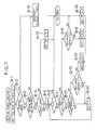
- Fig. 1 is a block diagram of a musical tone generator of an electronic musical instrument in accordance with the invention;
- Fig. 2 shows in block outline the electronic musical instrument in an embodiment of the invention;
- Fig. 3 illustrates memory areas in a RAM;
- Fig. 4 shows data stored in a table;
- Figs. 5 to 7 are flowcharts respectively showing a timer-interrupt processing, key-on-event processing and a key-off-event processing which are executed in a micro-computer;
- Fig. 8 is a graph illustrating the timer-interrupt processing; and
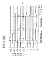
- Figs. 9(a) and 9(b) are time charts showing relationships between control signals and key-depression/-release of keys included in a second part of a keyboard.
- Referring first to Fig. 1, an electronic musical instrument has a musical tone generator which is provided with tone-pitch assigning means 1, manually operable members (keys) 2, control message-producing
means 3 connected to themembers 2 to receive and process the signals therefrom and musical tone-generating means 4 connected to the tone pitch-assigning means 1 and controlled by the message-producingmeans 3. Musical tone-controlling messages produced automatically by the message-producing means 3 correspond to the operation of the manuallyoperable members 2. - As is shown schematically in Fig. 2, the electronic musical instrument in one embodiment of the invention comprises a
keyboard 20 which is composed of 61 (sixty one) keys corresponding to C2-octave to C7-octave. Four white keys included in a range from "C2" to "F2" constitute asecond part 20A of the keyboard, with the remaining keys thereby constituting afirst part 20B of the keyboard. - In a playing mode "1" which is the usual playing mode, musical pitches are assigned to generated musical tones by means of both of the first and the
second parts circuit 29 generates, for each key-depression, four musical tones which are different from one another with respect to their pitches, timbres and volumes. On the other hand, in another playing mode "2" which is peculiar to the invention, the keys in thesecond part 20A produce control signals based on their key-depression or key-release states as well as based on speeds and pressures of such key operation, while pitch assignment and tone control are likewise conducted by thefirst part 20B as in the playing mode "1". - In more detail, the four white keys of "C2" to "F2" produce four control signals of different kinds so as to control the generated volume for each of the musical tones assigned by the keys in the
first part 20B. Thus, operation of the four keys in thesecond part 20A of the keyboard is effective to perform control of four kinds as to the generated volume of each musical tone. - A plurality of manually operable members (2) as manually operable means in the invention correspond to the four keys included in the
second part 20A of keyboard. Operation of the manually operable members (2) corresponds to the operated states such as key-depression and key-release, the speeds and pressure thereof as to saidsecond part 20A of the keyboard. Each of the abovementioned control signals is produced by integrating a first control signal component with a seecond control signal component, the first signal component being produced in accordance with the key-depression and key-release and the speeds thereof, while the second signal component is produced according to the pressure of depressed keys. - Each of the first control signal components, as will be described later in detail referring to Figs. 5 and 6, is produced to change itself asymptotically in the course of time with a given sharpness of change until it reaches a given ultimate or target level. The sharpness of change and the target level are provided by operation of the keys included in the
second part 20A of the keyboard, in particular by the key-depression and key-release and the speeds thereof. The electronic musical instrument further comprises a key operation-detectingcircuit 21 for sensing operation, i.e. , key-depression and key-release, of the keys on thekeyboard 20, avelocity detecting circuit 22 for sensing speeds of the key-depression and key-release and an after-touch-detectingcircuit 23 for sensing pressures imparted to the keys on thekeyboard 20 when they are depressed. Data which is produced as key information by these circuits is then fed to amicrocomputer 24 through abus 25, under control of said microcomputer. - A
control panel 26 also included in the musical instrument comprises settingmembers 26A to 26K and anindicator 26L which are shown in the drawing, as well as other manual members such as a timbre selection switch and a write-command switch which are not shown. Operations of these members also are detected under control of and fed to themicrocomputer 24 so that data or information obtained thereby are indicated on theindicator 26L also under control of said microcomputer. - The setting members which relate to the invention but do not constitute the manually operable members (2) are now described.
- Setting
member 26A: This is utilized to preset standard or target values for magnitudes of the first control signal components which are produced by key- depression (key-ON) of the keys on thesecond part 20A of the keyboard. - Setting
member 26B: This is utilized to preset values of another type relative to magnitudes of the first control signal components which are produced according to the speed of key-depression of the keys in thesecond part 20A of the keyboard. - Setting
member 26C: This is utilized to preset still other values relative to the sharpness of change in the course of time of the first control signal components which are produced when the keys in thesecond part 20A are depressed. - Setting
member 26D: This is utilized to preset further values relative to the sharpness of change in the course of time of the first control signal components in order to cause the sharpness to depend upon the key-depression speeds of the keys in saidsecond part 20A of the keyboard. - Setting
member 26E: This is utilized to preset still further values relative to the sharpness of change in the course of time of the first control signal components which are produced when the depressed keys in thesecond part 20A are released. - Setting
member 26F: This is utilized to preset yet further values relative to the sharpness of change in the course of time of the first control signal components in order to cause the sharpness to depend upon the key-release speeds of the keys in saidsecond part 20A of the keyboard. - Setting
member 26G: This member presets a threshold value "Vt" of key-depression speed which is utilized to cause the first control signal components to attenuate to "0" when the keys are depressed during a "hold" mode described later. - Setting
member 26H: This member is used to preset values relevant to relationship between the pressure of depressed keys insecond part 20A of the keyboard and the magnitudes of said second control signal components produced. - The above setting
members 26A to 26H are manipulated to select various relationships between the control signals and the operation of saidpart 20A of the keyboard during a presetting mode described below. - Setting member (switch) 26I: This is used to effect shift or changeover between the "hold" mode and another (non-hold) mode. the shift from the former to the latter and vice versa takes place whenever this setting member 26I is operated. In the non-hold mode, the four first control signal components are produced independently of one another, based on the key-depression and key-release and the speeds thereof of the four keys in
second part 20A of the keyboard, respectively. Key-depression gives rise to the first control signal components, while key-release attenuates same. In the "hold" mode, however, any key-release itself cannot cause such an attenuation of the first control signal components but can do so only if the other key is depressed after one key has been released. In this case, so-called "crossing" fade effects are easily produced because a previous musical tone continues to gradually attenuate until an instant when a new musical tone comes forth. If a key-depression speed of the newly depressed key is below the threshold value "Vt", then the first control signal components for keys other than the newly depressed key do not attenuate, with only said signal component for said newly depressed key thus attenuating to "0". Changeover between the "hold" mode and the other (non-hold) mode may also be carried out by means of apedal 27A described later. - Setting member (switch) 26J: This is used to make selection between operation modes. The operation modes include a playing mode "1", a playing mode "2" and a presetting mode. Changeover from one mode to another take place step-wise in the order mentioned above every time the setting member 26J is operated. In a state wherein one of the playing modes "1" and "2" is currently effective, another pedal 27B also provides means to make a changeover among the modes.
- Setting member (switch) 26K: This member is used to select one key among the four keys "C2" to "F2" in the
second part 20A of the keyboard which is to be preset during the presetting mode. Each operation of thismember 26K causes a sequential changeover from one key to the next. The setting of functions assigned to the keys insecond part 20A of the keyboard is performed for respective keys by means of thesetting members 26A to 26F and 26H, whereas setting by means of the settingmember 26G is common to all the keys whichever thereof is adjusted as to its assigned function. Apedal group 27 comprises thepedals pedal 27A serves for the changeover between the "hold" mode and the non-hold mode, the changeover occurring every time thepedal 27A is operated. Theother pedal 27B is operated either during the playing modes "1" or during the playing mode "2" so as to effect changeover from the former to the latter or vice versa, also such changeover occurring each time thepedal 27B is operated. Operation of thepedal group 27 is detected by a pedal operation-detectingcircuit 28 to produce pedal data which themicrocomputer 24 controls to receive same through thebus 25. - The
microcomputer 24 comprises a central processing unit (CPU) 24A adapted to execute given programs, a read-only memory (ROM) 24B for storing the given programs, a random access memory (RAM) 24C for execution of the programs, and atimer circuit 24D for the counting of time lapse during said programs. The random access memory (RAM) 24B has areas defined therein which include a memory zone and a working zone. Musical tone data and other data are written into the memory zone, while the working zone comprises various registers, data tables and other small areas necessary to the function of themicrocomputer 24. - The
RAM 24C is supported with a backup battery so that the data written therein is not degraded or last even in the event of a power failure. The programs referred to above are executed by themicrocomputer 24 on the basis of the tone data, the key information (such as the states as to key-depression and key-release, the speeds thereof and the pressures imparted to the keys) and other data in order to control a musical tone signal-generatingcircuit 29. The musical tone signal-generatingcircuit 29 comprises 32 (thirty two) tone-generators. Themicrocomputer 24 selects four of the tone-generators for each depression of the keys which are operated for generation of musical tones (i.e., for assignment of musical pitches). The selected tone-generators receive, from the microcomputer, control signals designating pitches, timbres, volumes and other parameters which are used by said tone-generators to generate musical tone signals of four kinds. In other words, the musical tone signal-generatingcircuit 29 generates four different musical tone signals which are different from each other in respect of the musical pitch, the musical timbre, the volume and the other parameters. The microcomputer can deal with a plurality of key-depressions at the same time and cause the circuit to simultaneously generate 8 (eight) musical tone signals at maximum. Themicrocomputer 24 produces control signals of another kind when the keys for generation of musical tones are released; said control signals are supplied to such tone-generators that correspond to the released keys, thereby attenuating the musical tone signals. Further details of transmission of control signals to the tone-generators selected in response to key-depression and key-release are not given here since they are well known in the art. Key-depression and key-release of said keys for generation of musical tones replace existing data written in theRAM 24C by new data for generation of control signals, in reponse to the new key-depression or new key-release. Themicrocomputer 24 further produces at regular intervals musical volume-controlling signals and supplies same to the musical tone signal-generatingcircuit 29. - The musical tone signal-generating
circuit 29 multiplies the control signals corresponding to key-depression of key-release of the keys for generation of musical tones by the musical volume-controlling signals which are supplied to saidcircuit 29 at regular intervals thereby to produce composite volume-controlling signals. Said signal-generatingcircuit 29 then generates final or synthetic musical tone signals based on the composite volume-controlling signals and the other control signals supplied by themicrocomputer 24. The synthetic musical tone signals thus produced are then amplified in anamplifier 30, converted into audible sounds and output from aspeaker 31. - Fig. 3 shows memory areas assigned to the working zone in
RAM 24C, the memory areas being used by themicrocomputer 24 to execute such processings as needed in the invention. A register "Key Nos." temporarily stores a key number designating a musical pitch of newly depressed or released key. The key-depression or key-release speed thereof is written in another register "Velocity". Another register "RVt" stores the threshold value "Vt" for key-depression speeds in the "hold" mode. Denoted by "BP1" to "After-1" are memory areas which are utilized to produce control signals when the key "C2" in thesecond part 20A of the keyboard is operated. Thus, the register "BP1" is for memory of the target level of the first control signal component which has a magnitude changing in the course of time. A further register "K1" is provided to write therein a value corresponding to sharpness of the change in magnitude of said control signal component. A still further register "Current-1" temporarily stores a current value of the first control signal component. - A table "BPT1" stores relationships between key-depresssion speeds and the target magnitude levels of first control signal components produced by key-press. Data in the table "BPT1" is set by means of the
setting members setting members - A still further table "KOFFT1" stores relationships between the key-release speeds and the values corresponding to sharpness of changes in the course of time of the produced first control signal components. Data in the table "KOFFT1" is set by means of the
setting members member 26H. The suffix "1" carried by the memory area names "BP1" to "After-1" indicates that said areas are for the key "C2" in thesecond part 20A of the keyboard. There are similarly provided such memory areas as will be indicated by, for example, "BP2", "BP3" respectively for the three other white keys "D2", "E2" and "F2" constituting the "four" keys in thesecond part 20A. - Data contained in the abovementioned tables is illustrated in Fig. 4 wherein given along the abscissa are key-depression and key-release speeds. The stored values are given along the ordinate. A solid line in Fig. 4 shows the relationship between the key-depression and/or key-release speeds and said stored values. A symbol "Vc" denotes a medial value (i.e. centre value between a maximum and a minimum), another symbol "Lc" denoting a value stored corresponding to the medial value "Vc". The aforementioned setting members preset the value "Lc" as well as the gradient of the inclined solid line.
- The aforedescribed setting members are classified into the followuing three groups, that is:
- Group "I" including the
setting members - Group "II" including the setting
members - Group "III" including the
setting members - At first, a method of making the tables will be described referring to Fig. 4. The value "Lc" is set by the setting members included in the group "I", and the gradient of an inclined solid line is set by means of the setting members included in the group "II". For example, the value "Lc" on the tables "BPT1" to "BPT4" is set by the setting
member 26A, and the gradient of said inclined solid line is set by the settingmember 26B. If said values thus set in such a procedure exceed a maximum or minimum value that can be received by relevant memory area or the like, then the maximum or minimum value is written thereinto in place of the actual values to be set. The setting members included in the groups "I" and "II" operated in this way make it possible to alter in various manners the relationships between the speeds of key-depression or key-release and the magnitudes of the produced first control signal components or the sharpness of thieir changes in the course of time. The same functions as above are applicable to all the other tables. - As described above, each table carries thereon various values corresponding to key-depression or key-release speeds and capable of being altered owing to operation of the setting members.
- It will now be apparent that any values within a large range of the control signal values can be read from said tables according to variable operation modes of the setting members and/or according to variable key-depression or key-release speeds. Figs. 5 to 8 show processings relevant to the invention and executed by the
microcomputer 24 when the playing mode "1" or "2" is selected. - The producing of the control signal components is carried out corresponding to the timer-interrupts which are given by a
timer circuit 24D as shown in Fig. 5, thetimer circuit 24D counting time lapse during this program. At Step A1, a decision is made as to which of the playing modes "1" and "2" has been selected. If the former is the current mode, then the process goes to Step A7, while the process advances to Step A2 in a case where the playing mode "2" is on. - At Step A2, "1" is set to "n". The number "n" denotes the keys wherein "1" to "4" respectively denote the white keys "C2" to "F2". At step A3, a decision is made as to whether "n" is "5" or not. If yes, then the process returns to the main routine processing, while the process will go to Step A4 in a case where "n" is not "5".
- At Step A4, each of current values of the first control signal components is subtracted from a corresponding target value thereof, the target values being those which are stored in the registers "BP[n], and the current values being those which are stored in the registers "Current[n]". each of differences thus obtained is then multiplied by a corresponding one of the values which represent the sharpness of change in the course of time of said first control signal components and which are stored in the registers "K[n]". (The values stored in the registers "K[n]" are "1" or less but higher than "0"). Each of the products obtained by such multiplications is added to the corresponding current value of said first signal component stored in the corresponding register "Current[n]" in order to produce a sum which is to be written thereinto as a new current value of said first component. At Step A5, a key-depression pressure of the key carrying the number "n" (shown as "Key pressure[n]" in Fig. 5) is multiplied by the corresponding value which is stored in the register "After[n]" and giving the relationship between said pressure and the second control signal component. A product (i.e., the second control signal component itself) thus obtained is added to the current value of the first signal component which is stored in the register "Current[n]". A sum thus obtained is the final musical volume-controlling signal and is supplied to the tone signal-generating
circuit 29. - At Step A6, "1" is added to the current number "n". the suffix "n" in the above description denotes such memory area or key-depression pressure for the key which carries the number "n", thus "BP[n]" means "BP1" when "n" is "1".
- At step A7, a maximum which is found among the musical volume-controlling signals is supplied to the tone signal-generating
circuit 29. - Fig. 6 shows the first control signal components resulting from the just described processing. Time lapse is measured along the abscissa and magnitudes of the data stored in the registers "BP1" to "BP4" and in the registers "Current-1" to "Current-4" are measured along the ordinate. It is assumed that these data stored in all the registers referred to here have a value "L0" until the instant "T0". It will however be seen from Fig. 6 that, when the data in the registers "BP1" to "BP4" become "L1" at the instant "T0" the other data stored in the registers "Current-1" to "Current-4" start to change at the sharpness of change stored in the further registers "K1" to "K4" so as to tend asympototically towards the target values stored in the registers "BP1" to "BP4". Consequently, the first control signal components can be produced to be of various sharpnesses in their change in the course of time if said data in the registers "BP1" to "BP4" and in the other registers "K1" to "K4" are varied.
- As will be understood from the above description, new control signal components are produced to be output and to be of magnitudes which change in the course of time in the playing mode "2", while the control signal components are invariably set at the maximum value in playing mode "1".
- If any key is depressed, then a key-on event routine is executed as illustrated in Fig. 7. At Step B1, a key number of the newly depressed key is written into the register "Key Nos.", and its key-depression speed is written into the register "Velocity". At Step B2, a decision is made as to which of the playing modes "1" and "2" has been selected.
- If the former is the current mode, then the process goes to Step B16, while the process advances to Step B3 in a case where the playing mode "2" is on.
- A decision is made at Step B3 as to whether the newly depressed key is or is not one included in the
second part 20A of the keyboard, based on the value currently carried by the register "Key Nos". If yes, then go to Step B4, but is no, then go to Step B16. - At Step B4, a decision is made as to whether the "hold" mode is currently effective or not. If yes, then go to step B5; but if no, then go to Step B15. At Step B5, "1" is set to the number "n" which denote the keys "C2" to "F2" for n=1 to n=4, respectively. At step B6, a decision is made as to whether "n" is or is not "5", and if yes, then returns to the main routine whereas the process goes to Step B7 in a case where "n" is not "5". At Step B7, a further decision is made as to whether the key carrying the number "n" is or is not the newly depressed key, and if yes, then go to Step B8, but if no, then go to Step B11. At Step B8, a still further decision is made as to whether the key-depression speed of the newly depressed key is less than the threshold value "Vt" or not, and if yes, then go to Step B9, but if no, then go to Step B10.
- At Step B9, selection is made to employ one of the registers "BP1" to "BP4" on the basis of the data in the register "Key Nos." so that "0" is written into the thus employed register. At the same time, further selection is made to employ one of the tables "KONT1" to "KONT4" which corresponds to the newly depressed key; the thus employed table is then read to ascertain the sharpness of change in the course of time of first control signal component, by means of the data stored in the register "Velocity". The sharpness of change thus ascertained is written into one of the registers "K1" to "K4" which corresponds to the newly depressed key.
- At Step B10, one table is selected from the tables "BPT1" to "BPT4" on the basis of the value which is then carried by the register "Key Nos.", the selected table corresponding to said newly depressed key. The target value of the first control signal component is read from said selected table by referring to the value then existing in the register "Velocity", said target value then being written into one of the registers "BP1" to BP4" which corresponds to the newly depressed key. Likewise, one table is selected from the tables "KONT1" to "KONT4" which corresponds to said newly depressed key. The value corresponding to the sharpness of change in the course of time of the first control signal component is read from the thus selected table by referring to the value then existing in the register "Velocity", said value which represents the sharpness of change then being written into one of the registers "K1" to "K4" which corresponds to the newly depressed key.
- At Step B11, a decision is made as to whether a key corresponding to "n" is under depression or not. If yes, then go to Step B14, but if no, then go to Step B12. At Step B12, a decision is made as to whether the key-depression speed value which has been written into the register "Velocity" is or is not smaller than the threshold value "Vt". If yes, then go to Step B14, but if no, then go to Step B13.
- At step B13, one register corresponding to "n" is selected from the registers "BP1" to "BP4", and "0" is written into the selected register. Further, one of the tables "KONT1" top "KONT4" is selected based on the value in the register "Key Nos." which corresponds to the newly depressed key. the value which corresponds to the sharpness of change in the course of time of the first control signal component is read from the thus selected table by referring to the value then existing in the register "Velocity", said value which represents the sharpness of change then being written into one of the registers "K1" to "K4" which carries "n" at that time. At Step B14, "1" is added to "n".
- The above processings are for the "hold" mode during the playing mode "2", and are such that which are carried out when one of the keys in the
second part 20A of the keyboard is depressed at any key depression speed higher than the threshold value "Vt" in order that the first control signal component for the newly depressed key is caused to change in its magnitude according to said sharpness which corresponds to the key depression speed until it will reach the target magnitude which also corresponds to said speed. At the same time, the coexisting first control signal component for the key which has already been released at that time is attenuated towards "0" with the same sharpness as that for the newly depressed one. However, in the case where the new key-depression is made at any speed below the threshold value "Vt", said first control signal component for the newly depressed key is contrarily attenuated towards "0" with the sharpness of change in the course of time, the sharpness also corresponding to said key-depression speed. - At Step B15, one of the tables "KONT1" to "KONT4"is selected based on the value in the register "Key Nos." which corresponds to the newly depressed key. The value which corresponds to the sharpness of change in the course of time of the first control signal component is read from the thus selected table by referring to the value then existing in the register "Velocity", said value which represents the sharpness of change then being written into one of the registers "K1" to "K4" which carries "n" at that time. the above processing is for the case where the "hold" mode is not selected during the playing mode "2", and is to be carried out when one of the keys in the
second part 20A of the keyboard is depressed so as to control the musical tones in such a manner that the first control signal component for the newly depressed key changes in its magnitude according to said sharpness which corresponds to the key depression speed until it will reach the target magnitude which also corresponds to said speed. - At Step B16, the control signals are supplied to musical tone signal-generating
circuit 29 based as well on the data relating to the depressed key as the tone data. This means that the newly depressed key is one of the keys used to generate musical tones so that the musical tone-generating processing is executed. - On the other hand, a key-off event-routine as shown in Fig. 8 shall be executed when the key which has been depressed is newly released. At Step C1 , a key number of the newly released key is written into the register "Key Nos." and its key-release speed is written into the register "Velocity".
- At Step C2, a decision is made as to whether the playing mode "1" has been selected or not. If yes, then go to Step C6. If no, i .e., if the playing mode "2" has been selected, then the process advances to Step C3.
- A decision is made at Step C3 on whether the newly released key is or is not included in the
second part 20A of the keyboard, based on the value currently carried by the register "Key Nos." If yes, then go to Step C4, but if no, then go to Step C6. - At Step C4, a decision is made as to whether the "hold" mode is currently continuing or not. If yes, then return to the main routine, but if no, then go to Step C5.
- At Step C5, selection is made to employ one of the registers "BP1" to "BP4" on the basis of the data in the register "Key Nos." so that "0" is written into the thus employed register. At the same time, further selection is made to employ one of the tables "KOFFT1" to "KOFFT4" which corresponds to the newly released key, the thus employed table is then read to ascertain the sharpness of change in the course of time of the first control signal component, by means of the data stored in the register "Velocity". The sharpness of change thus ascertained is written into one of the registers "K1" to "K4" which corresponds to the newly released key. The above processing is for the case where the "hold" mode is not selected during the playing mode "2", and is to be carried out when one of the keys in the
second part 20A of the keyboard is released for control of the musical tones in such a manner that the first control signal component for the newly released key is caused to change in its magnitude in accordance with the key release speed. On the contrary, such a processing of the first control signal component shall not be done if any key in thesecond part 20A is released when the "hold" mode prevails during the playing mode "2". - At Step C6, the control signals are supplied to musical tone signal-generating
circuit 29 based on the data relating to the released key as well as on the tone data. This means that the newly released key is one of the keys used to generate or mute musical tones so that the musical tone-muting processing is executed. - In summary, the abovedescribed key-on event-routine and key-off event-routine are such that, if the newly depressed or released key is for control of musical tones, then the first control signal components are themselves caused to change, while the musical tone-generating or -muting processing is done in the case where said newly depressed or released key is for generation of musical tones (i.e., for assignment of pitches to musical tones).
- Figs. 9(a) and 9(b) show the relationship between the control signals (i.e., said two signal components as a whole) and the key-depression or -release of the keys included in the first and
second parts second part 20A of the keyboard is incorporated here. - Fig. 9(a) illustrates some cases wherein the order of key-depressions and -releases as well as their speeds are varied as to the first and
second parts first part 20B of the keyboard (protruding areas thereby showing "key-depression"); the symbol "VT" indicates the speed of said key-depression or -release; the reference symbol "KC" indicates any key-depression or -release of any key in thesecond part 20A of the keyboard; the symbol "VC" indicates the speed of said key-depression or -release; the symbol "LT" indicates the musical volume-controlling signals produced based on the key-depression or -release speeds and on the tone data as to thefirst part 20B of keyboard; the symbol "LC" indicates the control signals which are produced corresponding to the key-depression or -release of the keys insecond part 20A (and which here do not include any second control signal component because any key-depression pressure is not made use of in this example, thus said signals being equal to the first control signal components); and the symbol "LE" indicates final volume-controlling signals each of which is derived from each corresponding signal "LT" and each corresponding signal "LC". - As shown in Fig. 9(a), if any key in the
first part 20B of the keyboard is depressed when a significant length of time has passed after any key in thesecond part 20A was depressed, then the final control signal "LE" is determined by the control signal "LT" which is the musical volume-controlling signal produced based on the key-depression or -release speed and on the tone data as to thefirst part 20B of the keyboard. On the other hand, if any key in thesecond part 20A of the keyboard is depressed when a significant length of time has passed after any key in thefirst part 20B was depressed, then the final control signal "LE" is determined by the control signal "LC" which is produced corresponding to the key-depression or -release of the keys in thesecond part 20A. Further, any change made as to the speed of key-depression or -release causes variation of the magnitude of and the sharpness of change in the course of time of said final control signal. - Fig. 9(b) illustrates a further case wherein several of the keys of the
second part 20A of the keyboard are depressed or released overlappingly and in different manners during the "hold mode". The symbols "KC2", "KD2" KE2 and "KF2" respectively indicate the key-depression or -release states of the keys "C2", "D2", "E2" and "F2" of saidsecond part 20A. The symbol "VF2" indicates key-depression or -release speed of the key "F2". Further symbols "L1", "L2", "L3" and "L4" indicate the control signals respectively corresponding to the keys "C2", "D2", "E2" and "F2" of saidsecond part 20A of the keyboard. (These control signals do not include any second control signal component because any key-depression pressure is not made use of in this example, said signals thus being equal to the first control signal components). - As seen in Fig. 9(b), the control signals do not attenuate but retain their magnitudes even if any key in said
second part 20A is released immediately after being depressed. A new key-depression with a speed slower than the threshold value "Vt" will however bring about an attenuation of first control signal component which corresponds to the newly depressed key. - Conversely, a different type of new key-depression with a speed higher than the threshold value "Vt" will however bring about a change in magnitude of the control signal corresponding to the new key-depression, the change occurring towards the target value in the course of time wherein said target value and the sharpness of said change are determined by the speed of said key-depression. On the other hand, the magnitude of control signal derived from any key which has already been released when the key referred to above is newly depressed will attenuate with the same sharpness of change as that with which said control signal produced by the newly depressed key changes in the course of time. The new key-depression is effective to produce a "crossing" fade effect. A control signal produced by any key which remains depressed when the new key-depression is made does not attenuate whereby a decision is left to the discretion of the operator as to whether the musical tone based on the key remaining depressed is to be maintained.
- Although only the first control signal components are described referring to Figs. 9(a) and 9(b) which change in their magnitudes in the course of time depending upon the key-depression or -release speed accompanying the touches on the
second part 20A of the keyboard, any additional pressures imparted to the already depressed keys can produce the second control signal components in the described embodiment whereby more sophisticated control of musical tone volumes may be achieved. - As described hereinabove, the control signals of various kinds obtained depending upon the various types of touches of the keys in the
second part 20A of the keyboard afford varied controls of musical tone volumes according to the embodiment of the invention. - Each table may be divided into several areas which respectively correspond to successive ranges of key- depression or -release speed, though one straight line is used in the embodiment to indicate the relationship between the key-depression or -release speed and the resulting control signal (except for those areas outside the maximum or minimum value).
- Although the same table is used for both the cases of "hold" and "non-hold" modes in the embodiment in order to store the relationship between the key-depression or -release speed and the obtained control signals, it is possible to employ two tables which are subjected to changeover from one to another according to the selected mode. In addition, such a table of the relationship between the key-depression speed and the first control signal components during the "hold" mode may be divided into two areas separated by the threshold value "Vt", thus enabling the sharpness of the "crossing" fade effects to be set independently upon the other sharpness of change of signals.
- Each relationship between the key-depression or -release speed and the control signals are previously written into the tables in the above embodiment, however it may be calculated each time when necessary.
- Although volume control of musical tones is performed by such a described system in the embodiment, the system may be modified to perform control of any other parameters such as pitch or timbre of each musical tone, degree of "chorus" effect or other musical effects, magnitude or speed of modulation signals, and the likes, as long as they are susceptible to treatment by the musical tone signal-generating
circuit 29. A plurality of parameters may be controlled by means of any single key. - It may also be possible that a suitable memory means stores, for each of the setting members disposed on the
control panel 26, several modes of relationship between operation of the keyboard's second part and control signals wherein one of the modes may be read from said memory for each setting member before starting to play music, although each setting member merely controls only one of such relationships in the embodiment. Further, each of such relationships between said operation and said control signals may be stored together with any other parameter such as timbre, musical effect or the like whereby the reading of latter parameter can simultaneously set former relation for each setting member for the keyboard's second part. - Any keys may be substituted for the keys "C2" to "F2" which are used consistently in the embodiment as the manually operable members producing detectable operation touches, if they are convenient for player's operation. There may be employed a further modified system in which some or all of the substituted keys can be chosen by the player at his discretion when he plays music. Further, any manually operable members of kinds different from the keys may be incorporated.
- The above system in the embodiment is such that both the key-depression or -release speed and the key-depression pressure are utilized as the operation touches for generating the control signals, however either one of them may singly be used for the said purpose. These two touches may be changed over between them.
- The manually operable members producing detectable touches may be of any type other than "keys".
- Although the keyboard provides the tone pitch-assigning means in the embodiment, any other suitable members may be used as such means.
- Although all of the tone pitch-assigning means, the manually operable members, the control message-producing means and the musical tone-generating means in the embodiment are incorporated in the single electronic musical instrument, they may be separately built in some instruments and interconnected with one another by an information transmitting means such as MIDI (Musical Instrument Digital Interface).
- Although the musical tone-controlling messages in the embodiment are of magnitudes which exponentially change in the course of time, the magnitudes may change linearly giving straight lines with respective gradients which may be utilized as the sharpness of change.
- Furthermore, any other number of musical tones may be generated for one key-depression, although four musical tones are generated in the embodiment. Any desirable timbres may be assigned to any keys for control of musical tones, though no reference has been made to such a case.
Claims (7)
Applications Claiming Priority (2)
| Application Number | Priority Date | Filing Date | Title |
|---|---|---|---|
| JP26381/89 | 1989-02-03 | ||
| JP1026381A JP2750530B2 (en) | 1989-02-03 | 1989-02-03 | Electronic musical instrument |
Publications (3)
| Publication Number | Publication Date |
|---|---|
| EP0381530A2 true EP0381530A2 (en) | 1990-08-08 |
| EP0381530A3 EP0381530A3 (en) | 1991-01-16 |
| EP0381530B1 EP0381530B1 (en) | 1994-08-10 |
Family
ID=12191948
Family Applications (1)
| Application Number | Title | Priority Date | Filing Date |
|---|---|---|---|
| EP90301143A Expired - Lifetime EP0381530B1 (en) | 1989-02-03 | 1990-02-02 | Electronic musical intrument |
Country Status (4)
| Country | Link |
|---|---|
| US (1) | US5097741A (en) |
| EP (1) | EP0381530B1 (en) |
| JP (1) | JP2750530B2 (en) |
| DE (1) | DE69011354D1 (en) |
Cited By (1)
| Publication number | Priority date | Publication date | Assignee | Title |
|---|---|---|---|---|
| EP1453035A1 (en) * | 2003-02-28 | 2004-09-01 | Yamaha Corporation | Musical instrument capable of changing style of performance through idle keys, method employed therefor and computer program for the method |
Families Citing this family (9)
| Publication number | Priority date | Publication date | Assignee | Title |
|---|---|---|---|---|
| JP3430515B2 (en) * | 1992-05-28 | 2003-07-28 | ヤマハ株式会社 | Signal input device for musical instruments |
| JPH0627946A (en) * | 1992-07-09 | 1994-02-04 | Kawai Musical Instr Mfg Co Ltd | Electronic keyboard musical instrument |
| JP3355743B2 (en) * | 1993-12-28 | 2002-12-09 | ヤマハ株式会社 | Electronic keyboard instrument |
| JP3586882B2 (en) * | 1994-03-28 | 2004-11-10 | ヤマハ株式会社 | Automatic performance system for keyboard instruments |
| US6066794A (en) * | 1997-01-21 | 2000-05-23 | Longo; Nicholas C. | Gesture synthesizer for electronic sound device |
| USRE37654E1 (en) * | 1996-01-22 | 2002-04-16 | Nicholas Longo | Gesture synthesizer for electronic sound device |
| US5789689A (en) * | 1997-01-17 | 1998-08-04 | Doidic; Michel | Tube modeling programmable digital guitar amplification system |
| JP4645282B2 (en) * | 2005-04-20 | 2011-03-09 | カシオ計算機株式会社 | Electronic musical instruments |
| JP5976362B2 (en) | 2012-03-29 | 2016-08-23 | 株式会社河合楽器製作所 | Electronic keyboard instrument |
Citations (3)
| Publication number | Priority date | Publication date | Assignee | Title |
|---|---|---|---|---|
| US4528885A (en) * | 1982-12-09 | 1985-07-16 | Nippon Gakki Seizo Kabushiki Kaisha | Touch-responsive apparatus in electronic musical instrument |
| EP0192984A2 (en) * | 1985-01-31 | 1986-09-03 | Yamaha Corporation | Selection device in an electronic musical instrument |
| EP0206786A2 (en) * | 1985-06-21 | 1986-12-30 | Yamaha Corporation | Tone signal generation device |
Family Cites Families (11)
| Publication number | Priority date | Publication date | Assignee | Title |
|---|---|---|---|---|
| JPS5387120U (en) * | 1976-12-17 | 1978-07-18 | ||
| JPS5387120A (en) * | 1977-01-11 | 1978-08-01 | Mitsubishi Electric Corp | Telephone control system for multi-directional multiplication common use |
| US4416178A (en) * | 1980-12-22 | 1983-11-22 | Casio Computer Co., Ltd. | Touch response providing apparatus |
| JPS57111589A (en) * | 1980-12-27 | 1982-07-12 | Casio Computer Co Ltd | Controlling system for tone color |
| DE3301354A1 (en) * | 1983-01-18 | 1984-07-19 | Matth. Hohner Ag, 7218 Trossingen | ELECTRONIC MUSIC INSTRUMENT |
| JPS60156097A (en) * | 1984-01-26 | 1985-08-16 | ヤマハ株式会社 | Touch response unit for electronic musical instrument |
| JPS62195189A (en) * | 1986-02-21 | 1987-08-27 | Nippon Telegr & Teleph Corp <Ntt> | Superconducting three-terminal device |
| JPS6365496A (en) * | 1986-09-06 | 1988-03-24 | 株式会社河合楽器製作所 | Key assigner system |
| EP0269052B1 (en) * | 1986-11-28 | 1993-08-11 | Yamaha Corporation | Electronic musical instrument |
| US4875400A (en) * | 1987-05-29 | 1989-10-24 | Casio Computer Co., Ltd. | Electronic musical instrument with touch response function |
| US4969385A (en) * | 1988-01-19 | 1990-11-13 | Gulbransen, Inc. | Reassignment of digital oscillators according to amplitude |
-
1989
- 1989-02-03 JP JP1026381A patent/JP2750530B2/en not_active Expired - Fee Related
- 1989-12-29 US US07/459,330 patent/US5097741A/en not_active Expired - Lifetime
-
1990
- 1990-02-02 DE DE69011354T patent/DE69011354D1/en not_active Expired - Lifetime
- 1990-02-02 EP EP90301143A patent/EP0381530B1/en not_active Expired - Lifetime
Patent Citations (3)
| Publication number | Priority date | Publication date | Assignee | Title |
|---|---|---|---|---|
| US4528885A (en) * | 1982-12-09 | 1985-07-16 | Nippon Gakki Seizo Kabushiki Kaisha | Touch-responsive apparatus in electronic musical instrument |
| EP0192984A2 (en) * | 1985-01-31 | 1986-09-03 | Yamaha Corporation | Selection device in an electronic musical instrument |
| EP0206786A2 (en) * | 1985-06-21 | 1986-12-30 | Yamaha Corporation | Tone signal generation device |
Cited By (2)
| Publication number | Priority date | Publication date | Assignee | Title |
|---|---|---|---|---|
| EP1453035A1 (en) * | 2003-02-28 | 2004-09-01 | Yamaha Corporation | Musical instrument capable of changing style of performance through idle keys, method employed therefor and computer program for the method |
| US6867359B2 (en) | 2003-02-28 | 2005-03-15 | Yamaha Corporation | Musical instrument capable of changing style of performance through idle keys, method employed therein and computer program for the method |
Also Published As
| Publication number | Publication date |
|---|---|
| JPH02205895A (en) | 1990-08-15 |
| JP2750530B2 (en) | 1998-05-13 |
| EP0381530A3 (en) | 1991-01-16 |
| US5097741A (en) | 1992-03-24 |
| EP0381530B1 (en) | 1994-08-10 |
| DE69011354D1 (en) | 1994-09-15 |
Similar Documents
| Publication | Publication Date | Title |
|---|---|---|
| US5119710A (en) | Musical tone generator | |
| EP0381530B1 (en) | Electronic musical intrument | |
| JP3117754B2 (en) | Automatic accompaniment device | |
| GB2129997A (en) | Electronic musical instrument with key touch detector and operator member | |
| US4205576A (en) | Automatic harmonic interval keying in an electronic musical instrument | |
| US5281756A (en) | Electronic musical instrument capable of assigning desired tones to a performance operator | |
| US4947724A (en) | Electric music instrument with the capability of memorizing and producing different musical scales | |
| US5074184A (en) | Controllable electronic musical instrument | |
| JPH0274997A (en) | Electronic musical instrument | |
| US5177314A (en) | Timbre setting device for an electronic musical instrument | |
| JP2858120B2 (en) | Electronic musical instrument | |
| JP2819616B2 (en) | Electronic musical instrument with portamento function | |
| JPS62208099A (en) | Musical sound generator | |
| US4389914A (en) | Chord identification system for electronic musical instruments | |
| US5177312A (en) | Electronic musical instrument having automatic ornamental effect | |
| JP2900457B2 (en) | Electronic musical instrument | |
| JP3261713B2 (en) | Tone generator | |
| JPH0584919B2 (en) | ||
| JPS6381396A (en) | Electronic musical instrument | |
| JPH10124050A (en) | Electronic musical instrument | |
| JPH0115878B2 (en) | ||
| US5483018A (en) | Automatic arrangement apparatus including selected backing part production | |
| JP2638090B2 (en) | Music parameter controller | |
| JPH0642146B2 (en) | Musical sound generator | |
| JP3241832B2 (en) | Music generator |
Legal Events
| Date | Code | Title | Description |
|---|---|---|---|
| PUAI | Public reference made under article 153(3) epc to a published international application that has entered the european phase |
Free format text: ORIGINAL CODE: 0009012 |
|
| AK | Designated contracting states |
Kind code of ref document: A2 Designated state(s): DE FR GB IT |
|
| PUAL | Search report despatched |
Free format text: ORIGINAL CODE: 0009013 |
|
| AK | Designated contracting states |
Kind code of ref document: A3 Designated state(s): DE FR GB IT |
|
| 17P | Request for examination filed |
Effective date: 19901221 |
|
| 17Q | First examination report despatched |
Effective date: 19920515 |
|
| GRAA | (expected) grant |
Free format text: ORIGINAL CODE: 0009210 |
|
| AK | Designated contracting states |
Kind code of ref document: B1 Designated state(s): DE FR GB IT |
|
| PG25 | Lapsed in a contracting state [announced via postgrant information from national office to epo] |
Ref country code: IT Free format text: LAPSE BECAUSE OF FAILURE TO SUBMIT A TRANSLATION OF THE DESCRIPTION OR TO PAY THE FEE WITHIN THE PRE;WARNING: LAPSES OF ITALIAN PATENTS WITH EFFECTIVE DATE BEFORE 2007 MAY HAVE OCCURRED AT ANY TIME BEFORE 2007. THE CORRECT EFFECTIVE DATE MAY BE DIFFERENT FROM THE ONE RECORDED.SCRIBED TIME-LIMIT Effective date: 19940810 Ref country code: FR Effective date: 19940810 |
|
| REF | Corresponds to: |
Ref document number: 69011354 Country of ref document: DE Date of ref document: 19940915 |
|
| PG25 | Lapsed in a contracting state [announced via postgrant information from national office to epo] |
Ref country code: DE Effective date: 19941111 |
|
| EN | Fr: translation not filed | ||
| PLBE | No opposition filed within time limit |
Free format text: ORIGINAL CODE: 0009261 |
|
| STAA | Information on the status of an ep patent application or granted ep patent |
Free format text: STATUS: NO OPPOSITION FILED WITHIN TIME LIMIT |
|
| 26N | No opposition filed | ||
| REG | Reference to a national code |
Ref country code: GB Ref legal event code: IF02 |
|
| PGFP | Annual fee paid to national office [announced via postgrant information from national office to epo] |
Ref country code: GB Payment date: 20040128 Year of fee payment: 15 |
|
| PG25 | Lapsed in a contracting state [announced via postgrant information from national office to epo] |
Ref country code: GB Free format text: LAPSE BECAUSE OF NON-PAYMENT OF DUE FEES Effective date: 20050202 |
|
| GBPC | Gb: european patent ceased through non-payment of renewal fee |
Effective date: 20050202 |