EP0381131A2 - Power controller with voltage-controlled circuit breaker - Google Patents
Power controller with voltage-controlled circuit breaker Download PDFInfo
- Publication number
- EP0381131A2 EP0381131A2 EP90101779A EP90101779A EP0381131A2 EP 0381131 A2 EP0381131 A2 EP 0381131A2 EP 90101779 A EP90101779 A EP 90101779A EP 90101779 A EP90101779 A EP 90101779A EP 0381131 A2 EP0381131 A2 EP 0381131A2
- Authority
- EP
- European Patent Office
- Prior art keywords
- circuit breaker
- voltage
- tripped
- operating voltage
- power controller
- Prior art date
- Legal status (The legal status is an assumption and is not a legal conclusion. Google has not performed a legal analysis and makes no representation as to the accuracy of the status listed.)
- Withdrawn
Links
Images


Classifications
-
- H—ELECTRICITY
- H02—GENERATION; CONVERSION OR DISTRIBUTION OF ELECTRIC POWER
- H02H—EMERGENCY PROTECTIVE CIRCUIT ARRANGEMENTS
- H02H3/00—Emergency protective circuit arrangements for automatic disconnection directly responsive to an undesired change from normal electric working condition with or without subsequent reconnection ; integrated protection
- H02H3/20—Emergency protective circuit arrangements for automatic disconnection directly responsive to an undesired change from normal electric working condition with or without subsequent reconnection ; integrated protection responsive to excess voltage
- H02H3/207—Emergency protective circuit arrangements for automatic disconnection directly responsive to an undesired change from normal electric working condition with or without subsequent reconnection ; integrated protection responsive to excess voltage also responsive to under-voltage
Definitions
- the present invention relates generaly to the field of electric power controller apparatus and, more particularly, to such apparatus having a manually-on and a manually- and electrically-off circuit breaker which controls one or more power outlets.
- a computer system may comprise a main frame computer, several disc drives, and one or more work stations.
- a typical sensor system may comprise a number of separately-powered sensors, as well as a monitor or controller.
- all the different pieces of electrical equipment comprising a particulr system may be separately plugged into building power outlets.
- a power controller By means of such a power controller, the pieces of electrical equipment powered thereby may be turned on all at once or in some preestablished manner.
- a power controller which shuts off all of the pieces of electrical equipment powered thereby in the event an emergency, an out-of-control, or some other preestablished condition occurs.
- the power controller may be desirable for the power controller to turn off the equipment powered thereby if the line voltage supplied through the controller increases or decreases beyond preestablished limits in order to reduce the risk of electrical damage to the controlled equipment.
- the power controller is configured for automatic, electrical turn-off but for manual-only turn-on. Normally, it is usually desirable that the power controller also have the capability for manual turn-off so that the equipment connected to the controller can be powered down at will by an operator.
- a principal objective of the present invention is, therefore, to provide a relatively inexpensive power controller which provides for automatic, electrical turn-off even when line power to the power controller is disrupted.
- a power controller apparatus which comprises a circuit breaker having an electrically-actuatable trip coil for enabling the circuit breaker to be tripped-off electrically and means for electrically connecting the circuit breaker to a source of operating voltage. Additionally comprising the power controller apparatus are at least one unswitched power outlet connected to the circuit breaker to receive operating voltage therefrom; means for monitoring the operating voltage from the voltage source and for providing a voltage indication when the operating voltage moves outside of a preestablished range; and logic control means for receiving such voltage indication and for tripping-off the circuit breaker in response thereto.
- the logic control means include a capacitor, means for charging the capacitor when the circuit breaker is tripped on, and relay means for connecting the capacitor to the circuit breaker trip coil for causing the energizing thereof in response to the receiving of the voltage indication.
- the operating voltage monitoring means include means enabling the setting of an upper line voltage limit and the separate setting of a lower line voltage limit, the upper and lower line voltage limits establishing the voltage range.
- the circuit breaker include manual switching means enabling the circuit breaker to be manually tripped-on and tripped-off and that the circuit breaker is configured so that after being tripped-off by the energizing of the trip coil, the circuit breaker remains off until it is manually tripped on.
- the logic control means include delay means for enabling the circuit breaker to stay manually tripped on while the line voltage is being established in the line monitoring means so that an initial indication of low voltage does not automatically trip off the circuit breaker.
- the power controller apparatus includes at least one switched power outlet connected for receiving operatingvoltage from the circuit breaker and including a switch for enabling the switched power outlet to be selectively turned on and off while the circuit breaker is tripped on.
- the power controller apparatus may include thermal protection means for providing a second voltage indication when the temperature in a monitored region of the apparatus exceeds a preestablished temperature, the logic control means being connected for receiving such second voltage indication and being operative for connecting the above-mentioned capacitor to the circuit breaker trip coil in response to the second voltage indication being received by the logic control means.
- the power controller apparatus may advantageously include means enabling the connection of an external bus thereto, in which case the logic control means is connected for receiving a third voltage indication from the external bus and is operative for connecting the above-mentioned capacitor to the circuit breaker trip coil in response to the third voltage indication being received by the logic control means.
- FIG. 1 there is depicted in FIG. 1, in conventional electrical block diagram form, an exemplary power controller 100 in which the present invention relating to a voltage-controlled circuit breaker 112 (described hereinbelow) can be used to advantage. It will, however, be appreciated from the following description that the present invention is not limited to use in a power controller, such as power controller 100.
- power controller 100 is merely used to illustrate one manner in which the present invention can be used and to serve as a vehicle whereby the invention can be clearly described.
- power controller 100 further comprises a power supply 114, a line voltage monitor 116, a logic control 118, an electric filter 120, a contactor (power relay) 122, a switched power outlet 124, and an unswitched power outlet 126.
- a power supply 114 Shown electrically connected to logic control 118 are a remote ON/OFF switch 130, a thermal protector 132, and an external fault detector 134, the latter of which may also be considered as a remote control bus.
- Circuit breaker 112 which is preferably a manual turn-on and manual and electrical turn-off type, is shown in FIG. 1 as being connected at an input side, for example, by a conventional plug 138 to a source of operating voltage , such as a building electrical outlet (not shown) which is considered to be 110 volts for power controller 100 as depicted and described herein. It is to be appreciated, however, that comparable power controller apparatus may be constructed for different line voltages (such as 220 volts) in a manner which will, from the following description, be apparent to those skilled in the electrical and electronic circuit design arts.
- circuit breaker 112 has a manually-operated ON/OFF switch or tripper 140.
- the output voltage of circuit breaker 112 is provided, through filter 120, directly to unswitched power outlet 126, which may include a plurality of conventional electrical outlet recepticles (not shown). Although the inclusion of filter 120 is generally preferred for enabling the filtering out of operating voltage spikes and noise in a conventional, known manner, the filter is not essential to operation of power controller apparatus 100.
- circuit breaker 112 is also provided, through contactor 122 to switched power outlet 124, which may also comprise a plurality of conventional electrical outlet receptacles.
- Contactor 122 is controlled, through logic control 118, by remote ON/OFF switch 130, so that switched outlets 124 can be deenergized without having to trip circuit breaker 112, through which the operating (line) voltage is provided to both switched and unswitched power outlets 124 and 126, respectively.
- the providing of contactor 122, switched power outlet 124 and remote ON/OFF switch 130 is not essential to power controller 100, but may be desirable for particular customer applications.
- contactor 122, switched power outlet 124, remote switch 130, and related circuitry does not affect the automatic tripping operation of circuit breaker 112, which is more particularly described below.
- the automatic tripping of circuit breaker 112 is responsive to the operating line voltage being outside a preselected range; that is, when the line voltage either increases above a preselected (preset) upper limit or decreases below a preselected (preset) lower limit. It may, for example (without any limitation being thereby intended or implied), be desirable for a line voltage of 110 volts and for some applications to preset the upper limit at about 132 volts and the lower limit at about 90 volts.
- line voltage monitor 116 to monitor a line voltage signal provided to it by power supply 114 and to provide a change of voltage state on FAIL HI or FAIL LO output lines connected to logic control 118 when the line voltage rises above the preset upper limit or falls below the preset lower limit.
- logic control 118 Responsive to such a voltage state change on either FAIL HI or FAIL LO lines, logic control 118 is configured for causing (through power supply 114) the electrical tripping-off of circuit breaker 112, thereby causing the deenergizing of both switched power outlet 124 (assuming such outlet is provided and has been energized by operation of remote ON/OFF switch 130) and unswitched power outlet 126.
- tripping-off of circuit breaker 112 deenergizes entire power controller 100.
- logic control 118 be operative for causing the automatic electrical tripping-off of circuit breaker 112 whenever thermal protector 132 indicates an excessively high temperature (that is, exceeds a predetermined temperature limit) and/or when a signal on remote control bus indicates some sort of defined fault.
- thermal protector 132 and remote control bus 134 must be in their "normal" state and the line voltage must be within the preset upper and lower limits before circuit breaker 112 will stay latch when it is manually tripped on. If any of the mentioned inputs (that is, thermal protector 132, remote control bus 134, FAIL HI and FAIL LO) are in a non-normal condition indicative of a problem of some sort, circuit breaker 112 will not stay latched on.
- circuit breaker 112 is configured so that once tripped-off by operation of logic control 118, the circuit breaker must be manually switched back on before power control apparatus 100 is again operable.
- An important advantage associated with this type of circuit breaker configuration and operation is that after a condition arises which causes the automatic tripping-off of circuit breaker 112, an operator has the opportunity to inspect the system and, if desired, unplug any particularly sensitive electrical equipment from outlets 124 and/or 126 before the the circuit breaker is tripped back on, in case there may be some problem with power controller 100 itself
- circuit breaker 112 it can, perhaps, be appreciated that it is difficult to provide automatic electrical tripping-off of circuit breaker 112 in a situation in which all electrical line power is interrupted--that is, when the operating line voltage drops to zero.
- the electrical tripping-off of circuit breaker 112 is accomplished by the connecting of a charged electrical capacitor, designated in a conventional manner in FIGS 1, 2 and 5 as "C13", across a tripping coil 142 of circuit breaker 112. As described below, capacator C13 is connected in a manner causing it to become charged to line voltage during normal operation of power controller 100.
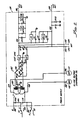
- Fig. 2 depicts, in electrical schematic drawing form, a presently preferred manner in which power supply 114 can be electronically implemented.
- power supply 114 is configured to operate on 110 volts AC input, received over conduits 144 and 146 from the voltage output side of filter 120 (FIG. 1), and to provide a nominal +5.1 volts DC output on conduit 148, a nominal -6.2 volts DC output on conduit 150, a nominal +12 volts DC output on conduit 152, and a nominal -12 volts DC output on conduit 154.
- power supply 112 is configured for providing nominal +5 volt AC signals, identified, respectively, as ACP (AC power) and ACR (AC return), on respective output conduits 156 and 158.
- Comprising power supply 114 are a transformer 160 which provides a 28 volt AC output and a full wave rectifier 162 which provides +/- 12 volt DC outputs for conduits 152 and 154.
- a diode designated on FIG. 2 as "CR14”
- R25 resistor
- capacitor C13 Connected between resistor R25 and capacitor C13 are connected to the other side of capacitor C13 are the contacts of relay K1 which control the discharge of capacitor C13 into circuit breaker tripping coil 142
- Connected to the other side of capacitor C13 are the contacts of relay K2 which energize contactor 122, (FIG. 1).
- FIG. 2 Other interconnected electronic components (conventional resistors, capacitors, diodes, regulators and comparators) of power supply 114 are designated in FIG. 2 in a conventional manner known to those skilled in the electronics art, it being, therefore, considered unnecessary to specifically describe all such components and the manner in which they are interconnected to provide the above-listed voltage outputs. Values of these other electronic components of power supply 114, as well as their designation or part numbers, are as shown in Table A and/or Table B below.
- line voltage monitor 116 is to monitor the operating voltage provided to power controller apparatus 100 and to provide an output signal change of state on FH (fail high) output conduit 170 or on FL (fail low) output conduit 172 in response to the line voltage either increasing above the preset upper voltage limit or falling below the preset lower voltage limit.
- Change of state signals on conduits 170 and 172 are provided to logic control 118, which acts on the change of state of either of the FH and FL signals to cause the electrical tripping of circuit breaker 112 by voltage applied to trip coil 142 by capacitor C13.
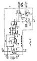
- line voltage monitor 116 can be electronically implemented in a number of different ways, a circuit which the present inventors have found practical and economical is depicted in electronic schematic form in FIG. 3, on which the various electronic components are identified in a conventional manner known to those skilled in the electronics art, and which are identified, with appropriate values given, in Table A and/or Table B below.
- variable resistors identified as "R3" and “R7”, by means of which the upper voltage limit and lower voltage limit are manually “set” by appropriate variation (adjustment) of such resistors.
- resistors R3 and R7 may, for example, be set for upper and lower operating voltage limits by varying the line voltage up and down by any known means and adjusting the resistors until circuit breaker 112 is tripped-off at the desired upper and lower voltage levels.
- the output voltage on FH and FL output conduits 170 and 172 are maintained at ground when the line voltage (as represented by inputs provided to line voltage monitor 116 over ACP and ACR conduits 156 and 158, respectively) is within the preselected upper and lower voltage limits.
- the voltage on respective conduits 170 (FH) and 172 (FL) changes abruptly to about +5 volts DC.
- line voltage monitor 116 is provided +12 volts DC over conduit 152, -12 volts DC over conduit 154, and -6.2 volts DC over conduit 150.
- logic control 118 is depicted in electric schematic form in FIG. 4 and in a more simplified, logic form in FIG. 5. Looking first at the simplified logic form of FIG. 5, it is seen that logic control 118 can be generally conidered as comprising an OR gate 190, the output of which is connected, through a driver 192, to the energizing coil of relay K1. Fed (in parallel) into OR gate 190 are the FH signal on conduit 170, the FL signal on conduit 172, and the external fault signal on conduit 134.
- logic control operates so that the output of driver 192 applies 0 volts DC to energize the coil of relay K1, thereby opening the normally closed relay contacts and keeping capacitor C13 electrically isolated from tripping coil 142 of circuit breaker 112--thereby keeping the breaker from being tripped.
- logic control 118 includes a driver 194 to the input of which is connected a conduit 196 in which remote ON/OFF switch 130 is installed.
- the output of driver 194 is connected to the coil of relay K2.
- ON/OFF switch 130 When ON/OFF switch 130 is open, the coil of relay K2 is not energized and coil 198 of contactor 122 (FIG. 1) is not energized. Consequently, no voltage is applied from circuit breaker 112 to switched power outlet 124.
- ON/OFF switch is closed, the K2 relay coil is energized, closing the contacts of the relay and thereby energizing contactor coil 198, in turn, applying operating line voltage, through contactor 122, to switched power output 124.
- logic control 118 (i) to automatically trip-off circuit breaker 112 to completely shut off power controller apparatus 100, and (ii) to enable the turning on and off of operating voltage to switched power outlet 124 without tripping off the circuit breaker can be electronically implemented in a number of different ways.
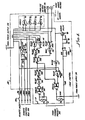
- the particular implementation shown in electronic schematic form in FIG. 4 has been found advantageous by the present inventors.
- all electronic components used in constructing logic control 118 are shown and identified in FIG. 4 and/or Tables A and B, it is considered unnecessary to describe in further detail the configuration of the logic circuit other than as described below.
- a time delay circuit 200 which is connected, by an electric conduit 202, to one side of the K2 relay coil and which includes a grounded emitter, NPN transistor, identified as "Q1." It can be appreciated that immediately after circuit breaker 112 is tripped-on manually after having, for any reason been tripped- off, a low line voltage may be sensed by line voltage monitor 116, which then signals (over FL conduit 172) logic control 118 to automatically trip-off the circuit breaker.
- time delay circuit 200 to delay the deenergizing of K1 relay coil for a sufficient (short) time after circuit breaker 112 has been tripped-on to enable an accurate line voltage check to be made by line voltage monitor 116.
- remote control bus 134 may, as depicted in the electrical schematic of FIG. 4, consist of several external lines 134 a-d so as to provide to logic control 118 "fault" signals of more than one type and/or from more than one source.
- electrical isolation may be provided by an optically-coupling circuit 204 which includes a conventional solid state device 206 internally comprising a light emitting diode 208 and a phototransistor 210.
- optical coupling circuit 204 protects logic control from electrical overloads on lines 134a and 134b.
Abstract
Description
- The present invention relates generaly to the field of electric power controller apparatus and, more particularly, to such apparatus having a manually-on and a manually- and electrically-off circuit breaker which controls one or more power outlets.
- Many different electrical (or electronic) systems are known which are comprised of a number of different pieces of separately-powered electrical equipment. As an example, a computer system may comprise a main frame computer, several disc drives, and one or more work stations. As another example, a typical sensor system may comprise a number of separately-powered sensors, as well as a monitor or controller.
- In some instances, all the different pieces of electrical equipment comprising a particulr system may be separately plugged into building power outlets. On the other hand, it is often preferred that all, or at least some, of the different pieces of electrical equipment comprising a particular system receive power from a common piece of electrical equipment commonly called a power controller. By means of such a power controller, the pieces of electrical equipment powered thereby may be turned on all at once or in some preestablished manner. For example, U.S. patent No. 4,719,364 to Pequet, et al., discloses an electrical power controller apparatus which provides a plurality of time-delayed power outlets which enable a like plurality of different pieces of electrical equipment to be powered-up (that is, turned on) in a predetermined time sequence with time delays possible between each turn-on. In turn, U.S. patent No. 4,769,555, also to Pequet, et al., discloses a power controller apparatus which provides both time-delayed powering-up and powering-down of electrical or electronic equipment which is connected to the apparatus.
- In some electrical systems, it is desirable to have a power controller which shuts off all of the pieces of electrical equipment powered thereby in the event an emergency, an out-of-control, or some other preestablished condition occurs. As an illustration, it may be desirable for the power controller to turn off the equipment powered thereby if the line voltage supplied through the controller increases or decreases beyond preestablished limits in order to reduce the risk of electrical damage to the controlled equipment. In this regard, it is, for example, often the case that computer disc drives can be damaged if the driving voltage decreases significantly below its normal 110 or 220 volt level.
- However, it may, at the same time, be undesirable to automatically power-up the controlled equipment when the emergency or out-of-control situation ceases or is cured. Instead, it may be preferred, once an emergency or out-of-control situation has caused the electrical equipment connected to the power controller to be shut down, to check out the system before the equipment is powered back up. In order to accomodate such a mode of operation, it is advantageous if the power controller is configured for automatic, electrical turn-off but for manual-only turn-on. Normally, it is usually desirable that the power controller also have the capability for manual turn-off so that the equipment connected to the controller can be powered down at will by an operator.
- It is, however, difficult to provide economical power controllers which can be automatically turned off by electrical power when the situation necessitating the turn-off is failure of line power to the controller.
- A principal objective of the present invention is, therefore, to provide a relatively inexpensive power controller which provides for automatic, electrical turn-off even when line power to the power controller is disrupted.
- In accordance with the present invention there is provided a power controller apparatus which comprises a circuit breaker having an electrically-actuatable trip coil for enabling the circuit breaker to be tripped-off electrically and means for electrically connecting the circuit breaker to a source of operating voltage. Additionally comprising the power controller apparatus are at least one unswitched power outlet connected to the circuit breaker to receive operating voltage therefrom; means for monitoring the operating voltage from the voltage source and for providing a voltage indication when the operating voltage moves outside of a preestablished range; and logic control means for receiving such voltage indication and for tripping-off the circuit breaker in response thereto. Included in the logic control means are a capacitor, means for charging the capacitor when the circuit breaker is tripped on, and relay means for connecting the capacitor to the circuit breaker trip coil for causing the energizing thereof in response to the receiving of the voltage indication. Preferably the operating voltage monitoring means include means enabling the setting of an upper line voltage limit and the separate setting of a lower line voltage limit, the upper and lower line voltage limits establishing the voltage range.
- It is preferred that the circuit breaker include manual switching means enabling the circuit breaker to be manually tripped-on and tripped-off and that the circuit breaker is configured so that after being tripped-off by the energizing of the trip coil, the circuit breaker remains off until it is manually tripped on. Further, it is preferred that the logic control means include delay means for enabling the circuit breaker to stay manually tripped on while the line voltage is being established in the line monitoring means so that an initial indication of low voltage does not automatically trip off the circuit breaker.
- According to an embodiment of the invention, the power controller apparatus includes at least one switched power outlet connected for receiving operatingvoltage from the circuit breaker and including a switch for enabling the switched power outlet to be selectively turned on and off while the circuit breaker is tripped on. Moreover, the power controller apparatus may include thermal protection means for providing a second voltage indication when the temperature in a monitored region of the apparatus exceeds a preestablished temperature, the logic control means being connected for receiving such second voltage indication and being operative for connecting the above-mentioned capacitor to the circuit breaker trip coil in response to the second voltage indication being received by the logic control means.
- The power controller apparatus may advantageously include means enabling the connection of an external bus thereto, in which case the logic control means is connected for receiving a third voltage indication from the external bus and is operative for connecting the above-mentioned capacitor to the circuit breaker trip coil in response to the third voltage indication being received by the logic control means.
- The present invention can be more readily understood by a consideration of the following detailed description when taken in conjunction with the accompanying drawings, in which:
- FIG. 1 is a schematic block diagram of an exemplary power controller apparatus having a circuit breaker which, in accordance with the present ivention, is capable of manual-only turn-on and of automatic, electrical turn-off when the line voltage to which the circuit breaker is connected is out of a preestablished range, and even in the event of line voltage interruption;
- FIG. 2 is an electrical schematic drawing showing an exemplary electronic implementation of a power supply portion of the power controller apparatus of FIG. 1;
- FIG. 3 is an electrical schematic drawing showing an exemplary electronic implementation of a line voltage monitor (voltage comparitor) portion of the power controller apparatus of FIG. 1;
- FIG. 4 is an electrical schematic drawing showing an exemplary electronic implementation of a logic control portion of the power controller apparatus of FIG. 1; and
- FIG. 5 is a simplified schematic drawing of the line voltage monitor the power supply and the logic control portions of the power controller of FIG. 1.
- In the various FIGS. like elements and features are given the same reference number and/or other identification.
- There is depicted in FIG. 1, in conventional electrical block diagram form, an
exemplary power controller 100 in which the present invention relating to a voltage-controlled circuit breaker 112 (described hereinbelow) can be used to advantage. It will, however, be appreciated from the following description that the present invention is not limited to use in a power controller, such aspower controller 100. In this regard,power controller 100 is merely used to illustrate one manner in which the present invention can be used and to serve as a vehicle whereby the invention can be clearly described. - As is more particularly described below,
power controller 100 further comprises apower supply 114, aline voltage monitor 116, alogic control 118, anelectric filter 120, a contactor (power relay) 122, a switchedpower outlet 124, and anunswitched power outlet 126. Shown electrically connected tologic control 118 are a remote ON/OFF switch 130, athermal protector 132, and anexternal fault detector 134, the latter of which may also be considered as a remote control bus. -
Circuit breaker 112, which is preferably a manual turn-on and manual and electrical turn-off type, is shown in FIG. 1 as being connected at an input side, for example, by aconventional plug 138 to a source of operating voltage , such as a building electrical outlet (not shown) which is considered to be 110 volts forpower controller 100 as depicted and described herein. It is to be appreciated, however, that comparable power controller apparatus may be constructed for different line voltages (such as 220 volts) in a manner which will, from the following description, be apparent to those skilled in the electrical and electronic circuit design arts. In addition to being configured for electrical tripping-off, as described below,circuit breaker 112 has a manually-operated ON/OFF switch ortripper 140. - The output voltage of
circuit breaker 112 is provided, throughfilter 120, directly tounswitched power outlet 126, which may include a plurality of conventional electrical outlet recepticles (not shown). Although the inclusion offilter 120 is generally preferred for enabling the filtering out of operating voltage spikes and noise in a conventional, known manner, the filter is not essential to operation ofpower controller apparatus 100. - As further shown in FIG. 1, the voltage output of
circuit breaker 112 is also provided, throughcontactor 122 to switchedpower outlet 124, which may also comprise a plurality of conventional electrical outlet receptacles.Contactor 122 is controlled, throughlogic control 118, by remote ON/OFF switch 130, so that switchedoutlets 124 can be deenergized without having to tripcircuit breaker 112, through which the operating (line) voltage is provided to both switched andunswitched power outlets contactor 122, switchedpower outlet 124 and remote ON/OFF switch 130 (and the associated circuitry described below) is not essential topower controller 100, but may be desirable for particular customer applications. As such,contactor 122, switchedpower outlet 124,remote switch 130, and related circuitry does not affect the automatic tripping operation ofcircuit breaker 112, which is more particularly described below. - Advantageously, the automatic tripping of
circuit breaker 112 is responsive to the operating line voltage being outside a preselected range; that is, when the line voltage either increases above a preselected (preset) upper limit or decreases below a preselected (preset) lower limit. It may, for example (without any limitation being thereby intended or implied), be desirable for a line voltage of 110 volts and for some applications to preset the upper limit at about 132 volts and the lower limit at about 90 volts. Also as more particularly described below, it is the function ofline voltage monitor 116 to monitor a line voltage signal provided to it bypower supply 114 and to provide a change of voltage state on FAIL HI or FAIL LO output lines connected tologic control 118 when the line voltage rises above the preset upper limit or falls below the preset lower limit. Responsive to such a voltage state change on either FAIL HI or FAIL LO lines,logic control 118 is configured for causing (through power supply 114) the electrical tripping-off ofcircuit breaker 112, thereby causing the deenergizing of both switched power outlet 124 (assuming such outlet is provided and has been energized by operation of remote ON/OFF switch 130) andunswitched power outlet 126. Of course, such tripping-off ofcircuit breaker 112 deenergizesentire power controller 100. - It is also preferred, in many customer applications, that
logic control 118 be operative for causing the automatic electrical tripping-off ofcircuit breaker 112 wheneverthermal protector 132 indicates an excessively high temperature (that is, exceeds a predetermined temperature limit) and/or when a signal on remote control bus indicates some sort of defined fault. In the particular embodiment ofpower controller 100 illustrated and described herein, boththermal protector 132 andremote control bus 134 must be in their "normal" state and the line voltage must be within the preset upper and lower limits beforecircuit breaker 112 will stay latch when it is manually tripped on. If any of the mentioned inputs (that is,thermal protector 132,remote control bus 134, FAIL HI and FAIL LO) are in a non-normal condition indicative of a problem of some sort,circuit breaker 112 will not stay latched on. - In any event,
circuit breaker 112 is configured so that once tripped-off by operation oflogic control 118, the circuit breaker must be manually switched back on beforepower control apparatus 100 is again operable. An important advantage associated with this type of circuit breaker configuration and operation is that after a condition arises which causes the automatic tripping-off ofcircuit breaker 112, an operator has the opportunity to inspect the system and, if desired, unplug any particularly sensitive electrical equipment fromoutlets 124 and/or 126 before the the circuit breaker is tripped back on, in case there may be some problem withpower controller 100 itself - It can, perhaps, be appreciated that it is difficult to provide automatic electrical tripping-off of
circuit breaker 112 in a situation in which all electrical line power is interrupted--that is, when the operating line voltage drops to zero. In the present invention, again as more particularly described below, the electrical tripping-off ofcircuit breaker 112 is accomplished by the connecting of a charged electrical capacitor, designated in a conventional manner in FIGS 1, 2 and 5 as "C13", across a trippingcoil 142 ofcircuit breaker 112. As described below, capacator C13 is connected in a manner causing it to become charged to line voltage during normal operation ofpower controller 100. - Fig. 2 depicts, in electrical schematic drawing form, a presently preferred manner in which
power supply 114 can be electronically implemented. As shown,power supply 114 is configured to operate on 110 volts AC input, received overconduits conduit 148, a nominal -6.2 volts DC output onconduit 150, a nominal +12 volts DC output onconduit 152, and a nominal -12 volts DC output onconduit 154. In addition,power supply 112 is configured for providingnominal + 5 volt AC signals, identified, respectively, as ACP (AC power) and ACR (AC return), onrespective output conduits - Comprising
power supply 114 are a transformer 160 which provides a 28 volt AC output and a full wave rectifier 162 which provides +/- 12 volt DC outputs forconduits voltage input conduits breaker tripping coil 142 Connected to the other side of capacitor C13 are the contacts of relay K2 which energizecontactor 122, (FIG. 1). - Other interconnected electronic components (conventional resistors, capacitors, diodes, regulators and comparators) of
power supply 114 are designated in FIG. 2 in a conventional manner known to those skilled in the electronics art, it being, therefore, considered unnecessary to specifically describe all such components and the manner in which they are interconnected to provide the above-listed voltage outputs. Values of these other electronic components ofpower supply 114, as well as their designation or part numbers, are as shown in Table A and/or Table B below. - As mentioned above, the function of
line voltage monitor 116 is to monitor the operating voltage provided topower controller apparatus 100 and to provide an output signal change of state on FH (fail high)output conduit 170 or on FL (fail low) output conduit 172 in response to the line voltage either increasing above the preset upper voltage limit or falling below the preset lower voltage limit. Change of state signals onconduits 170 and 172 are provided tologic control 118, which acts on the change of state of either of the FH and FL signals to cause the electrical tripping ofcircuit breaker 112 by voltage applied totrip coil 142 by capacitor C13. - Although line voltage monitor 116 can be electronically implemented in a number of different ways, a circuit which the present inventors have found practical and economical is depicted in electronic schematic form in FIG. 3, on which the various electronic components are identified in a conventional manner known to those skilled in the electronics art, and which are identified, with appropriate values given, in Table A and/or Table B below. Of particular note, however, are variable resistors, identified as "R3" and "R7", by means of which the upper voltage limit and lower voltage limit are manually "set" by appropriate variation (adjustment) of such resistors. These resistors R3 and R7 may, for example, be set for upper and lower operating voltage limits by varying the line voltage up and down by any known means and adjusting the resistors until
circuit breaker 112 is tripped-off at the desired upper and lower voltage levels. - In the particular line voltage moitoring circuit depicted schematically in FIG. 3, the output voltage on FH and
FL output conduits 170 and 172 are maintained at ground when the line voltage (as represented by inputs provided to line voltage monitor 116 over ACP andACR conduits power supply 114,line voltage monitor 116 is provided +12 volts DC overconduit 152, -12 volts DC overconduit 154, and -6.2 volts DC overconduit 150. - Inasmuch as the configuration of
line voltage monitor 116 is set forth in detail in FIG. 3 (in conventional electronic notation) , it is considered unnecessary to further describe the circuit herein. Such circuitry is, however, depicted in simplified, logic form in FIG. 5, which depicts the ACP and ACR inputs (onrespective conduits 156 and 158) being fed to the input of adifferential amplifier 180, the output of which is, in turn, fed to adriver 182. The output ofdriver 182 is, in turn, fed to the input of each ofvoltage comparators voltage comparators conduit 170 and the FL signal on conduit 172. -
Logic control 118 is depicted in electric schematic form in FIG. 4 and in a more simplified, logic form in FIG. 5. Looking first at the simplified logic form of FIG. 5, it is seen thatlogic control 118 can be generally conidered as comprising anOR gate 190, the output of which is connected, through adriver 192, to the energizing coil of relay K1. Fed (in parallel) into ORgate 190 are the FH signal onconduit 170, the FL signal on conduit 172, and the external fault signal onconduit 134. - Under normal operating conditions of power controller 100 (that is, when the operating line voltage is between the preestablished upper and lower limits and there are no faults on external bus 134), logic control operates so that the output of
driver 192 applies 0 volts DC to energize the coil of relay K1, thereby opening the normally closed relay contacts and keeping capacitor C13 electrically isolated from trippingcoil 142 ofcircuit breaker 112--thereby keeping the breaker from being tripped. Hoverer, in the event that any of the above-mentioned input signals to ORgate 190 changes state (due to the line voltage increasing or decreasing above or below the preestablished limits, as reflected by a change of voltage state onFL conduit 170 or FL conduit 172 or to a fault on external bus 134), the output of the OR gate output todriver 192 changes state, thereby causing the driver to deenergize the coil of relay K1. In consequence, the normally-closed contacts of relay K1 close, thereby electrically connecting capacitor C13 to trippingcoil 142 ofcircuit breaker 112, the voltage from the capacitor energizing the trip coil and trippingcircuit breaker 112 off. - It can also be seen from the simplified logic schematic of FIG. 5 that
logic control 118 includes adriver 194 to the input of which is connected aconduit 196 in which remote ON/OFF switch 130 is installed. The output ofdriver 194 is connected to the coil of relay K2. When ON/OFF switch 130 is open, the coil of relay K2 is not energized andcoil 198 of contactor 122 (FIG. 1) is not energized. Consequently, no voltage is applied fromcircuit breaker 112 to switchedpower outlet 124. When ON/OFF switch is closed, the K2 relay coil is energized, closing the contacts of the relay and thereby energizingcontactor coil 198, in turn, applying operating line voltage, throughcontactor 122, to switchedpower output 124. - The above-described operations of logic control 118 (i) to automatically trip-
off circuit breaker 112 to completely shut offpower controller apparatus 100, and (ii) to enable the turning on and off of operating voltage to switchedpower outlet 124 without tripping off the circuit breaker can be electronically implemented in a number of different ways. However,the particular implementation shown in electronic schematic form in FIG. 4 has been found advantageous by the present inventors. Inasmuch as all electronic components used in constructinglogic control 118 are shown and identified in FIG. 4 and/or Tables A and B, it is considered unnecessary to describe in further detail the configuration of the logic circuit other than as described below. - Beyond that which was described above for
logic control 118 relative to FIG. 5, it is seen from FIG. 4, that there is advantageously provided a time delay circuit 200, which is connected, by an electric conduit 202, to one side of the K2 relay coil and which includes a grounded emitter, NPN transistor, identified as "Q1." It can be appreciated that immediately aftercircuit breaker 112 is tripped-on manually after having, for any reason been tripped- off, a low line voltage may be sensed byline voltage monitor 116, which then signals (over FL conduit 172)logic control 118 to automatically trip-off the circuit breaker. It is, therefore, the function of time delay circuit 200 to delay the deenergizing of K1 relay coil for a sufficient (short) time aftercircuit breaker 112 has been tripped-on to enable an accurate line voltage check to be made byline voltage monitor 116. - Also,
remote control bus 134 may, as depicted in the electrical schematic of FIG. 4, consist of severalexternal lines 134 a-d so as to provide tologic control 118 "fault" signals of more than one type and/or from more than one source. As shown for lines 134a and 134b, electrical isolation may be provided by an optically-coupling circuit 204 which includes a conventionalsolid state device 206 internally comprising alight emitting diode 208 and aphototransistor 210. Suchoptical coupling circuit 204 protects logic control from electrical overloads on lines 134a and 134b. - Since a number of the various, identified solid state gates used to implement logic control 118 (as shown in FIG. 4) are economically available in multiple-gate integrated circuits, some of the available gates are unused. The circuit schematic of FIG. 4 shows these unused gates as "spares" having unconnected outputs. Such spares are advantageously available for use in the event any of the gates already used malfunction or otherwise become unusable.
- As mentioned above, all of the electronic components shown in the circuit schematic drawings of FIGS. 2, 3, and 4 are identified in the schematics and their descriptions--and part numbers, as appropriate--are listed in the following Tables A and B.
TABLE A PCB NO. DESCRIPTION PART NO. QT. R1, R15 RESISTOR, 4.7K, 5%, 1/4W 2 R2 RESISTOR, 9.5K, 1%, 1/4W 1 R3,R7 POTENTIOMETER, 10K, 20-TURNS EVM-CEGA01B14 2 R4, R6 RESISTOR, 4.99K, 1%, 1/4W 2 R5 RESISTOR, IM, 5%, 1/4W 1 R8 RESISTOR, 6.49K, 1%, 1/4W 1 R10 RESISTOR, 560, 5%, 1/2W 1 R11 RESISTOR, 750K, 5%, 1/4W 1 R12 RESISTOR, 15.4K, 1%, 1/4W 1 R13 RESISTOR, 3.9K, 5%, 1/4W 1 R14, R16, R17, R26 RESISTOR, 10K, 1%, 1/4W 4 R18, R19 RESISTOR, 232K, 1%, 1/4W 2 R20, R24, R29 RESISTOR, 10K, 5%, 1/4W 3 R21, R22, R23 RESISTOR, 20K, 1%, 1/4W 3 R25 RESISTOR, 1K, 5%, 3W, WIRE WOUND 1 R27 RESISTOR, 680, 5%, 1/4W 1 R28 RESISTOR, 6.8K, 5%,1/4W 1 R30 RESISTOR, 39, 5%, 2W, WIRE WOUND 1 C1, C2, C3 CAPACITOR, 1000uf, 35V, ALUM. ELECT. 3 C4, C5, C8, C9, C14 CAPACITOR, 10uf, 25V, SOLID TANTALUM 5 C6, C10, C11, C15 CAPACITOR, .1uf, 25-50V, CERAMIC 4 C7 CAPACITOR, 1uf, 25V, SOLID TANTALUM 1 C12 CAPACITOR, 50uf, 16V, SOLID TANTALUM 1 C13 CAPACITOR, 100uf, 250V, ALUM. ELECT. 1 NOTE: 1% RESISTORS ARE METAL FILM 5% RESISTORS ARE CARBON FILM TABLE B PCB NO. DESCRIPTION PART NO. QT. CR1, CR2, CR3, CR4 RECTIFIER DIODE 1N4004 4 CR5, CR6, CR7, CR8, CR9 SIGNAL DIODE 1N4148 5 CR10, CR11, CR12, CR13, CR15 SIGNAL DIODE 1N4148 5 CR16, CR17, CR18, CR19, CR20 SIGNAL DIODE 1N4148 5 CR14 RECTIFIER DIODE 1N4007 1 CR21 ZENER DIODE, 5.1V , 1W 1N4733A 1 CR22 ZENER DIODE, 6.2V, 250mW 1N823A 1 F1 FUSE, 1/2A, PCB MOUNT 1 K1, K2 RELAY, 12VDC COIL, 120V 3A CONTACTS G2R-114P-US-VD 2 RN1 RESISTOR NETWORK, 9 X 1K, SIP EXB-F10E102G 1 T1 TRANSFORMER, 120/240V 28V CT @ 10VA 14A-10-28 1 Q1 NPN TRANSISTOR 2N3904 OR 2N4124 1 S1 THERMAL CUTOUT, 60°C, NORMALLY CLOSED 1 U1 +12VDC REGULATOR MC7812TC 1 U2 -12VDC REGULATOR 79712 1 U3 DUAL COMPARATOR LM393N 1 U4, U5 DUAL OP AMP LM1458N 2 U6 TTL INVERTER 74LSO4 1 U7 OPTICAL COUPLER, 200% CTR, 2500V BRKDN H11B2 1 U8 PERIPHERAL DRIVER 75452B 1 U9,U10 TTL NOR GATE 74LS02 2 - Although there is described above a specific arrangement of a power controller apparatus having a voltage-controller turn-off in accordance with the present invention for the purpose of illustrating the manner in which the invention can be used to advantage, it is to be appreciated that the invention is not limited thereto. Accordingly, any and all variations and modifications which may occur to those skilled in the art are to be considered to be within the scope and spirit of the invention as defined by the appended claims.
Claims (9)
a. a circuit breaker (112) having an electrically-actuable trip coil (142) for enabling the circuit breaker (112) to be tripped-off electrically;
b. means (138) for electrically connecting the circuit breaker (112) to an operating voltage;
c. at least one unswitched power outlet (126) connected to the circuit breaker (112) to receive operating voltage therefrom;
d. operating voltage monitoring means (116) for monitoring said operating voltage and for providing a voltage indication (FH, FL) when the operating voltage moves outside of a preestablished operating voltage range; and
e. logic control means (118) for receiving said voltage indication (FH, FL) and for tripping-off the circuit breaker (112) in response thereto,
said control means (118) having associated therewith a capacitor (C13) and means for charging the capacitor (C13) when the circuit breaker (112) is tripped on and is receiving said operating voltage and relay means (K1) for connecting the charged capacitor (C13) to the circuit breaker trip coil (142) for thereby causing the energizing thereof in response to said voltage indication (FH, FL).
a. a circuit breaker (112) having an electrically-actuable trip coil (142) for enabling the circuit breaker (112) to be tripped-off electrically, the circuit breaker (112) including manual tripping means (140) for enabling the circuit breaker (112) to be manually tripped-on and tripped-off, the circuit breaker (112) being configured so that after being tripped-off by the energizing of the trip coil (142), the circuit braker (112) remains tripped-off until being manually tripped-on;
b. means (138) for electrically connecting the circuit breaker (112) to an operating voltage;
c. at least one unswitched power outlet (126) connected to the circuit breaker (112) to receive operating voltage therefrom;
d. operating voltage monitoring means (116) for monitoring said operating voltage and for providing a voltage indication (FH, FL) when the operating voltage moves outside of a preestablished operating voltage range; and
e. logic control means (118) for receiving said voltage indication (FH, FL) and for tripping-off the circuit breaker (112) in response thereto,
said control means (118) having associated therewith a capacitor (C13) and means for charging the capacitor (C13) when the circuit breaker (112) is tripped-on and is receiving said operating voltage and relay means (K1) for connecting the charged capacitor (C13) to the circuit breaker trip coil (142) for thereby causing the energizing thereof in response to said voltage indication (FH, FL).
Applications Claiming Priority (2)
| Application Number | Priority Date | Filing Date | Title |
|---|---|---|---|
| US303912 | 1989-01-30 | ||
| US07/303,912 US4918562A (en) | 1989-01-30 | 1989-01-30 | Power controller with voltage-controlled circuit breaker |
Publications (2)
| Publication Number | Publication Date |
|---|---|
| EP0381131A2 true EP0381131A2 (en) | 1990-08-08 |
| EP0381131A3 EP0381131A3 (en) | 1991-06-26 |
Family
ID=23174240
Family Applications (1)
| Application Number | Title | Priority Date | Filing Date |
|---|---|---|---|
| EP19900101779 Withdrawn EP0381131A3 (en) | 1989-01-30 | 1990-01-30 | Power controller with voltage-controlled circuit breaker |
Country Status (4)
| Country | Link |
|---|---|
| US (1) | US4918562A (en) |
| EP (1) | EP0381131A3 (en) |
| JP (1) | JPH03198617A (en) |
| CA (1) | CA2008660A1 (en) |
Cited By (5)
| Publication number | Priority date | Publication date | Assignee | Title |
|---|---|---|---|---|
| EP0542040A2 (en) * | 1991-11-11 | 1993-05-19 | Mitsubishi Denki Kabushiki Kaisha | Trip control device for circuit breaker |
| EP0904621A1 (en) * | 1996-03-07 | 1999-03-31 | Nextek Power Systems, Inc. | Modular power management system and method |
| AU766009B2 (en) * | 1998-09-18 | 2003-10-09 | Service Smart Pty Ltd | A voltage monitor for a power line |
| CN103022959A (en) * | 2013-01-11 | 2013-04-03 | 南阳防爆电气研究所有限公司 | Method and device for adhesion detection of main contact of alternating-current contactor |
| CN105609373A (en) * | 2015-12-18 | 2016-05-25 | 武汉钢铁(集团)公司 | Intermediate relay capable of automatically cutting off load during auxiliary point adhesion |
Families Citing this family (29)
| Publication number | Priority date | Publication date | Assignee | Title |
|---|---|---|---|---|
| US5337205A (en) * | 1990-07-24 | 1994-08-09 | Square D Company | Dual voltage power supply |
| US5378931A (en) * | 1993-03-31 | 1995-01-03 | Allen-Bradley Company, Inc. | Low leakage fuse blown detection circuit |
| US5450334A (en) * | 1993-11-01 | 1995-09-12 | Pulizzi Engineering, Inc. | One time programmable switched-output controller |
| US7171461B2 (en) * | 1996-07-23 | 2007-01-30 | Server Technology, Inc. | Network remote power management outlet strip |
| US7043543B2 (en) * | 1996-07-23 | 2006-05-09 | Server Technology, Inc. | Vertical-mount electrical power distribution plugstrip |
| US7774443B2 (en) * | 1996-07-23 | 2010-08-10 | Server Technology, Inc. | Power-manager configuration upload and download method and system for network managers |
| US6711613B1 (en) | 1996-07-23 | 2004-03-23 | Server Technology, Inc. | Remote power control system |
| US7099934B1 (en) * | 1996-07-23 | 2006-08-29 | Ewing Carrel W | Network-connecting power manager for remote appliances |
| US6157360A (en) * | 1997-03-11 | 2000-12-05 | Silicon Image, Inc. | System and method for driving columns of an active matrix display |
| US5923103A (en) * | 1997-03-31 | 1999-07-13 | Pulizzi Engineering, Inc. | Switched-output controller apparatus with repeater function and method for constructing same |
| US6118639A (en) * | 1997-05-30 | 2000-09-12 | Goldstein; Richard | Fast acting disconnect system for protecting surge suppressors and connected utilization equipment from power line overvoltages |
| US5962935A (en) * | 1997-12-04 | 1999-10-05 | Geisert; Harold J. | Appliance protection latch |
| CA2428285A1 (en) * | 2002-05-06 | 2003-11-06 | Cyber Switching, Inc. | Method and/or system and/or apparatus for multiple interface remotely configurable power supply |
| US7550870B2 (en) * | 2002-05-06 | 2009-06-23 | Cyber Switching, Inc. | Method and apparatus for remote power management and monitoring |
| US7142950B2 (en) | 2004-05-28 | 2006-11-28 | American Power Conversion Corporation | Methods and apparatus for providing and distributing standby power |
| WO2006015366A2 (en) | 2004-07-31 | 2006-02-09 | Server Technology, Inc. | Transfer switch with arc suppression |
| US7514815B2 (en) * | 2004-09-28 | 2009-04-07 | American Power Conversion Corporation | System and method for allocating power to loads |
| US20060072531A1 (en) * | 2004-10-04 | 2006-04-06 | Ewing Carrel W | Communication network |
| KR20060130310A (en) * | 2005-06-14 | 2006-12-19 | 삼성전자주식회사 | Electronic apparatus and control method thereof |
| US7446437B2 (en) | 2005-07-22 | 2008-11-04 | American Power Conversion Corporation | Apparatus and method for preventing an electrical backfeed |
| WO2007056116A2 (en) * | 2005-11-02 | 2007-05-18 | Server Technology, Inc. | Power distribution load shedding system and method of use |
| US8876548B2 (en) * | 2008-03-31 | 2014-11-04 | Panduit Corp. | Rack unit outlet spacing for power outlet units |
| US8106670B2 (en) * | 2008-11-24 | 2012-01-31 | Schneider Electric USA, Inc. | Two pole circuit breaker voltage monitoring integration |
| US8649143B2 (en) * | 2008-11-24 | 2014-02-11 | Schneider Electric USA, Inc. | Improper voltage detection for electronic circuit breaker |
| US8200370B2 (en) | 2008-12-04 | 2012-06-12 | American Power Conversion Corporation | Energy reduction |
| US20100145884A1 (en) * | 2008-12-04 | 2010-06-10 | American Power Conversion Corporation | Energy savings aggregation |
| US9792552B2 (en) | 2012-06-29 | 2017-10-17 | Schneider Electric USA, Inc. | Prediction of available generator running time |
| DE102014110481A1 (en) * | 2014-07-24 | 2016-01-28 | Hamburg Innovation Gmbh | Protective device for electrical energy supply networks, energy source, power supply network and use of such a protective device |
| DE112018003754T5 (en) * | 2017-09-29 | 2020-04-16 | Aisin Aw Co., Ltd. | Inverter control device |
Citations (4)
| Publication number | Priority date | Publication date | Assignee | Title |
|---|---|---|---|---|
| DE2637389A1 (en) * | 1976-08-19 | 1978-02-23 | Siemens Ag | Low power disconnecting switch - has voltage monitoring device controlling switch operating automatic cut=out with electromagnetic high speed trip |
| DE2747787A1 (en) * | 1976-11-25 | 1978-06-01 | Zentronik Veb K | Multiple power supply checking unit - has logic circuit for indication and sequence control and uses comparator outputs as routing switch control |
| US4584623A (en) * | 1983-11-07 | 1986-04-22 | Watsco, Inc. | Electrical load protection device |
| EP0300091A2 (en) * | 1987-07-24 | 1989-01-25 | Pulizzi Engineering, Inc. | Multiple time delay power controller apparatus with time delay turn-on and turn-off |
Family Cites Families (5)
| Publication number | Priority date | Publication date | Assignee | Title |
|---|---|---|---|---|
| US3590325A (en) * | 1970-03-16 | 1971-06-29 | Westinghouse Electric Corp | Undervoltage detection and energy storage trip current |
| US3644790A (en) * | 1970-03-25 | 1972-02-22 | Westinghouse Electric Corp | Static antipump circuit breaker closing system |
| US3813579A (en) * | 1970-11-09 | 1974-05-28 | Rucker Co | Electric receptacle assembly with ground fault protection |
| US3740738A (en) * | 1971-04-26 | 1973-06-19 | Westinghouse Electric Corp | Undervoltage trip circuit for circuit breaker |
| US4331996A (en) * | 1979-08-22 | 1982-05-25 | Westinghouse Electric Corp. | Time delayed undervoltage relay |
-
1989
- 1989-01-30 US US07/303,912 patent/US4918562A/en not_active Expired - Lifetime
-
1990
- 1990-01-26 CA CA002008660A patent/CA2008660A1/en not_active Abandoned
- 1990-01-30 EP EP19900101779 patent/EP0381131A3/en not_active Withdrawn
- 1990-01-30 JP JP2021919A patent/JPH03198617A/en active Pending
Patent Citations (4)
| Publication number | Priority date | Publication date | Assignee | Title |
|---|---|---|---|---|
| DE2637389A1 (en) * | 1976-08-19 | 1978-02-23 | Siemens Ag | Low power disconnecting switch - has voltage monitoring device controlling switch operating automatic cut=out with electromagnetic high speed trip |
| DE2747787A1 (en) * | 1976-11-25 | 1978-06-01 | Zentronik Veb K | Multiple power supply checking unit - has logic circuit for indication and sequence control and uses comparator outputs as routing switch control |
| US4584623A (en) * | 1983-11-07 | 1986-04-22 | Watsco, Inc. | Electrical load protection device |
| EP0300091A2 (en) * | 1987-07-24 | 1989-01-25 | Pulizzi Engineering, Inc. | Multiple time delay power controller apparatus with time delay turn-on and turn-off |
Cited By (9)
| Publication number | Priority date | Publication date | Assignee | Title |
|---|---|---|---|---|
| EP0542040A2 (en) * | 1991-11-11 | 1993-05-19 | Mitsubishi Denki Kabushiki Kaisha | Trip control device for circuit breaker |
| EP0542040A3 (en) * | 1991-11-11 | 1993-09-29 | Mitsubishi Denki Kabushiki Kaisha | Trip control device for circuit breaker |
| US5375032A (en) * | 1991-11-11 | 1994-12-20 | Mitsubishi Denki Kabushiki Kaisha | Trip control device for circuit breaker |
| EP0904621A1 (en) * | 1996-03-07 | 1999-03-31 | Nextek Power Systems, Inc. | Modular power management system and method |
| EP0904621A4 (en) * | 1996-03-07 | 2000-05-10 | Nextek Power Systems Inc | Modular power management system and method |
| AU766009B2 (en) * | 1998-09-18 | 2003-10-09 | Service Smart Pty Ltd | A voltage monitor for a power line |
| CN103022959A (en) * | 2013-01-11 | 2013-04-03 | 南阳防爆电气研究所有限公司 | Method and device for adhesion detection of main contact of alternating-current contactor |
| CN103022959B (en) * | 2013-01-11 | 2014-12-24 | 南阳防爆电气研究所有限公司 | Method and device for adhesion detection of main contact of alternating-current contactor |
| CN105609373A (en) * | 2015-12-18 | 2016-05-25 | 武汉钢铁(集团)公司 | Intermediate relay capable of automatically cutting off load during auxiliary point adhesion |
Also Published As
| Publication number | Publication date |
|---|---|
| CA2008660A1 (en) | 1990-07-30 |
| JPH03198617A (en) | 1991-08-29 |
| US4918562A (en) | 1990-04-17 |
| EP0381131A3 (en) | 1991-06-26 |
Similar Documents
| Publication | Publication Date | Title |
|---|---|---|
| EP0381131A2 (en) | Power controller with voltage-controlled circuit breaker | |
| US4384213A (en) | Automatic transfer control device | |
| US4947278A (en) | Remote sensing power disconnect circuit | |
| US20050243491A1 (en) | Multi-function power monitor and circuit protector | |
| US4368499A (en) | Electrical equipment protection apparatus | |
| US20060164780A1 (en) | Electrical barrier | |
| US4509088A (en) | Motor protector relay with memory of overload | |
| US4817045A (en) | Monitored control arrangement | |
| US4724374A (en) | Solid state current limited power controller for DC circuits | |
| JPH02183817A (en) | Power unit | |
| WO1994006190A1 (en) | Dual voltage power supply | |
| US3789269A (en) | Overvoltage protection circuit | |
| US3454781A (en) | Super-fast switching device,using either direct or rectified alternating current,more particularly applied for substituting one power source to another | |
| US4327397A (en) | Computer power/temperature protector | |
| JP2020036527A (en) | Dc overvoltage monitoring and protection device, and direct current dc electrical system interconnection | |
| US4520909A (en) | Clutch actuator | |
| US3290556A (en) | Overcurrent static relay | |
| US6441556B1 (en) | Integrated fault protection for switched electronic systems for satellite applications | |
| US3277320A (en) | Time delay circuit | |
| US4063148A (en) | First house protector for voltage regulators and the like | |
| KR20210041876A (en) | Source transfer switch with automatic bypass function | |
| GB1588781A (en) | Automatic power transfer control device for selectively energising a network from a pair of electrical power sources | |
| US2724781A (en) | Voltage-regulated power supply systems | |
| US3417254A (en) | Solid-state overvoltage protection circuit | |
| GB1253983A (en) | D.c. generator apparatus |
Legal Events
| Date | Code | Title | Description |
|---|---|---|---|
| PUAI | Public reference made under article 153(3) epc to a published international application that has entered the european phase |
Free format text: ORIGINAL CODE: 0009012 |
|
| AK | Designated contracting states |
Kind code of ref document: A2 Designated state(s): AT DE FR GB IT SE |
|
| PUAL | Search report despatched |
Free format text: ORIGINAL CODE: 0009013 |
|
| AK | Designated contracting states |
Kind code of ref document: A3 Designated state(s): AT DE FR GB IT SE |
|
| 17P | Request for examination filed |
Effective date: 19911122 |
|
| STAA | Information on the status of an ep patent application or granted ep patent |
Free format text: STATUS: THE APPLICATION HAS BEEN WITHDRAWN |
|
| 18W | Application withdrawn |
Withdrawal date: 19921106 |
|
| R18W | Application withdrawn (corrected) |
Effective date: 19921106 |