EP0380320A2 - An optical pickup apparatus - Google Patents
An optical pickup apparatus Download PDFInfo
- Publication number
- EP0380320A2 EP0380320A2 EP90300741A EP90300741A EP0380320A2 EP 0380320 A2 EP0380320 A2 EP 0380320A2 EP 90300741 A EP90300741 A EP 90300741A EP 90300741 A EP90300741 A EP 90300741A EP 0380320 A2 EP0380320 A2 EP 0380320A2
- Authority
- EP
- European Patent Office
- Prior art keywords
- order diffracted
- zero
- side portions
- pickup apparatus
- optical pickup
- Prior art date
- Legal status (The legal status is an assumption and is not a legal conclusion. Google has not performed a legal analysis and makes no representation as to the accuracy of the status listed.)
- Granted
Links
Images


Classifications
-
- G—PHYSICS
- G11—INFORMATION STORAGE
- G11B—INFORMATION STORAGE BASED ON RELATIVE MOVEMENT BETWEEN RECORD CARRIER AND TRANSDUCER
- G11B7/00—Recording or reproducing by optical means, e.g. recording using a thermal beam of optical radiation by modifying optical properties or the physical structure, reproducing using an optical beam at lower power by sensing optical properties; Record carriers therefor
- G11B7/12—Heads, e.g. forming of the optical beam spot or modulation of the optical beam
- G11B7/135—Means for guiding the beam from the source to the record carrier or from the record carrier to the detector
- G11B7/1353—Diffractive elements, e.g. holograms or gratings
-
- G—PHYSICS
- G11—INFORMATION STORAGE
- G11B—INFORMATION STORAGE BASED ON RELATIVE MOVEMENT BETWEEN RECORD CARRIER AND TRANSDUCER
- G11B7/00—Recording or reproducing by optical means, e.g. recording using a thermal beam of optical radiation by modifying optical properties or the physical structure, reproducing using an optical beam at lower power by sensing optical properties; Record carriers therefor
- G11B7/12—Heads, e.g. forming of the optical beam spot or modulation of the optical beam
- G11B7/123—Integrated head arrangements, e.g. with source and detectors mounted on the same substrate
Definitions
- This invention relates to an optical pickup apparatus, and more particularly to an optical pickup apparatus which produces a laser beam for reading out information recorded on an information recording medium.
- optical disks having a high recording density and capable of recording large volumes of information have been finding many uses in various fields of application. Because of the high recording density of an optical disk, an optical pickup device for reading out information from the optical disk is provided with an optical system for focusing the laser beam onto a very small spot.
- Fig.7 of the accompanying drawings is a diagram illustrating the construction of a conventional optical pickup apparatus.
- the optical pickup apparatus of Figure 7 comprises a laser device 21 , a diffraction grating 22 , a beam splitter or half mirror 23 , a collimating lens 24 , an objective lens 25 , a plano-concave lens 27 , and a photodetector 28 , and is used for reading information recorded on an optical disk 26 on which information is stored in the form of pit tracks T ( Figure 8).
- a laser beam emitted from the laser device 21 is separated by the diffraction grating 22 into three beams, a zero-order diffracted beam and first-order diffracted beams in the positive and negative directions.
- these two first-order diffracted beams are referred to as "plus and minus first-order diffracted beams".
- the zero-order and first-order diffracted beams are then reflected by the beam splitter 23 , converted through the collimating lens 24 into parallel beams, and focused through the objective lens 25 to be projected onto the optical disk 26 .
- the beams reflected from the optical disk 26 pass through the objective lens 25 , the collimating lens 24 , the beam splitter 23 and the plano-concave lens 27 , and impinge onto the photodetector 28 which converts incident light beams into electric signals.
- the recording tracks are each formed in a very narrow width of 1 to 2 ⁇ m, a laser spot S projected onto the optical disk must be focused into a diameter of approximately 1 ⁇ m to match the recording track width.
- the objective 25 is required to have a high numerical aperture (NA) so that the size of the laser spot S is reduced while increasing the intensity of the beam.
- the diffraction grating 22 is provided with a light attenuation filter or neutral density filter (ND filter) 29 which partially covers the surface 22b opposite to the grating surface 22a (for example, Japanese Patent Publication (Kokai) No. 62-2,700,034).
- ND filter neutral density filter
- the center portion 22bc not covered by the ND filter 29 has a transmittance which is different from that of side portions 22bs covered by the ND filter 29 .
- the center portion 22bc is provided with a transmittance of 100%, while a transmittance of 10 to 40% is set for the side portions 22bs .
- the laser light spot is indicated by a circle L .
- the distribution of the laser beam intensity entering the objective lens 25 can be adjusted so that a laser beam of high intensity is obtained at the center of the spot S while reducing the laser beam intensity at the periphery thereof. This results in a weakened intensity of the Airy ring of the laser spot S , thereby hindering the occurrence of crosstalk even in the case of a narrow recording track width.
- the amount of the laser beam is partially reduced by the absorption or reflection of light caused by the ND filter 29, resulting in that part of the laser beam is not used. That is, the utilization efficiency of light in the prior art apparatus is inferior.
- an optical pick-up apparatus which comprises a light source and an optical device having a grating pattern for splitting a light beam from said light source into a zero-order diffracted beam and plus and minus first-order diffracted beams, said grating pattern having a centre portion and one or more side portions, the efficiency of said centre portion for the zero-order diffracted beam being greater than the efficiency of said side portions for the zero-order diffracted beam.
- the centre portion is embraced by said side portions.
- the duty ratio of the gratings in said centre portion is smaller than that in said side portions.
- the duty ratio of the gratings in said centre portion is greater than that in said side portions.
- an optical pickup apparatus which comprises a light source and an optical device having a grating pattern for separating a light beam from said light source into a zero-order diffracted beam and plus and minus first-order diffracted beams, said three beams being for focussing on an information recording medium having recording tracks, to thereby detect information stored in the recording tracks, said grating pattern having a centre portion and one or more side portions, the efficiency of said centre portion for the zero-order diffracted beam being greater than the efficiency of said side portions for the zero-order diffracted beam, and said centre portion being elongate in the direction which corresponds to the direction of the recording tracks.
- an optical pickup apparatus which comprises a light source and an optical device having a grating pattern for separating a light beam from said light source into a zero-order diffracted beam and plus and minus first-order diffracted beams, said grating pattern being formed on one surface of said optical device, and having a centre portion and one or more side portions, the efficiency of said centre portion for the zero-order diffracted beam being greater than the efficiency of said side portions for the zero-order diffracted beam, and said optical device having a hologram pattern for splitting a light beam incident thereon from the outside, said hologram pattern being formed on the other surface opposite to said one surface.
- the invention described herein makes possible the provision of (1) an optical pickup apparatus which has an excellent utilization efficiency of light; (2) an optical pickup apparatus which does not require any ND filter; (3) an optical pickup apparatus which can be easily manufactured; and (4) an optical pickup apparatus which can be manufactured at a reduced cost.
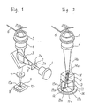
- Figure 1 illustrates an optical pickup apparatus according to the invention.
- the optical pickup apparatus of Figure 1 comprises a laser device 1 , a diffraction grating 2 , a beam splitter or half mirror 3 , a collimating lens 4 , an objective lens 5 , a plano-concave lens 7 , and a photodetector 8 .
- This apparatus is used for reading information recorded on an optical disk 6 .
- the diffraction grating 2 has a grating pattern formed on one surface 2a , as described later in more detail.
- the photodetector 8 comprises a first photodetecting element 9 which is divided into four sections, and second and third photodetecting elements 10a and 10b for detecting a tracking servo signal.
- the first photodetecting element 9 is used for detecting pit signals from the optical disk 6 and for detecting a tracking servo signal.
- a laser beam emitted from the laser device 1 is separated by the diffraction grating 2 into three beams, a zero-order diffracted beam and plus and minus first-order diffracted beams.
- the zero-order and first-order diffracted beams are then reflected by the beam splitter 3 , converted through the collimating lens 4 into parallel beams, and then focused through the objective lens 5 so as to be projected onto the optical disk 6 .
- the beams reflected from the optical disk 6 pass through the objective lens 5 , the collimating lens 4 , the beam splitter, 3 and the plano-concave lens 7 , and impinges onto the photodetector 8 which converts the beams into electric signals.
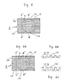
- the diffraction grating 2 is made of glass (having a refractive index of 1.52).
- the grating pattern formed on the surface 2a of the diffraction grating 2 has narrow-width grooves 11a and wide-width grooves 11b .
- the narrow-width grooves 11a are positioned at the center portion a , and the wide-width grooves 11b at the side portions b which sandwich the center portion a ( Figure 4).
- the center portion a has a rectangular shape in plan view which elongates in the direction of the tracks of the optical disk 6 , and is positioned so as to correspond with the track from which information is to be read out.
- the laser beam passing through the center portion a is provided with a reinforced intensity, while that passing through the side portions b comes out with a weakened intensity.
- FIG 3A the spot of a laser beam incident on the diffraction grating 2 is indicated by a circle L .
- Figure 4 diagrammatically illustrates the positional relation between the center portion a and the side portions b in a light spot L of the laser beam incident from the laser device 1 .
- the area of the center portion a in the light spot L is denoted as S A
- the sum of the areas of the side portions b in the light spot L as S B
- the diffraction efficiencies for the zero-order diffracted beam and plus and minus first-order diffracted beams passing through the portion a as ⁇ 0A and ⁇ 1A
- the diffraction efficiencies for the zero-order diffracted beam and plus and minus first-order diffracted beams passing through the portion b as ⁇ 0B and ⁇ 1B , respectively.
- T ⁇ 0A / ⁇ 0B (1)
- R S S A /S B
- K ( ⁇ 0B S B + ⁇ 0A S A )/( ⁇ 1B S B + ⁇ 1A S A ) (3)
- ⁇ 0A 0.682
- ⁇ 1A 0.054
- ⁇ 0B 0.232
- the zero-order beam diffraction efficiency ⁇ 0A through the center portion a is greater than the zero-order beam diffraction efficiency ⁇ 0B through the side portions b .
- T and R S are suitable values for reducing the size of an Airy ring which is produced around the converged spot S projected onto the optical disk 6 .
- K 2.7 is found.
- This value of K shows that the spectral ratio of the zero-order diffracted beam to the plus and minus first-order diffracted beams, i.e., the ratio of the main beam for reading out information from the optical disk 6 to the subbeams for obtaining the tracking servo signal therefrom can be produced in a proper balance.
- the width of the projecting portions is greater than that of the recessed portions (D0 > D1) in the center portion a , but conversely, the width of the recessed portions may be made greater than that of the projecting portions (D0 ⁇ D1) in the center portion a , as shown in Figure 3D.
- the same effect can be achieved in both the cases. In the latter case, however, grooves must be etched wider as shown by numeral 11c in Figure 3D, so that it may cause disadvantages that the output of an etching device (e.g., reactive ion etching device) must be larger, and that a longer etching time is required.
- an etching device e.g., reactive ion etching device
- the diffraction grating 2 has a grating pattern shown in Figure 5.
- the grating pattern shown in Figure 5 is also provided with a different duty ratio of recessed portions to projecting portions between the center portion and the side portions, but each recessed portion in the center portion has one of its boundary surfaces formed flush with one of the boundary surfaces of each recessed portion in the side portions.
- This pattern provides approximately the same characteristic as the pattern of Figure 3A, but since it has a fewer number of corners formed therein, the diffraction grating having the pattern of Figure 5 has the advantage in that the formation of a photomask by the electronic beam drawing technique can be achieved more easily.
- the diffraction grating 2 may have a grating pattern as shown in Figures 6A to 6C.
- the numeral 11a′ indicates grooves formed in the center portion of the diffraction grating 2
- the numeral 11b′ represents grooves formed in the side portions thereof.
- These two kinds of grooves 11a′ and 11b′ are formed parallel with the same pitch of 16 ⁇ m, and the duty ratio of the projection portion width D0 to the recessed portion width D1 is 1 : 1 for both grooves.
- the grooves 11b′ formed in the side portions have a depth sufficiently greater than that of the grooves 11a′ formed in the center portion.
- the depth of the grooves 11a′ is set at 0.29 ⁇ m, while the depth of the grooves 11b′ is set at 0.65 ⁇ m.
- the diffraction efficiency ⁇ 0A for the zero-order diffracted beam through the center portion is greater than the diffraction efficiency ⁇ 0B for the zero-order diffracted beam through the side portions.
- these values of T and R S are suitable ones for reducing the size of an Airy ring which is produced around the converged spot S projected onto the optical disk 6 .
- K 2.2 is found.
- This value of K shows that the spectral ratio of the zero-order diffracted beam to the plus and minus first-order diffracted beams, i.e., the ratio of the main beam for reading out information from the optical disk 6 to the subbeams for obtaining the tracking servo signal therefrom can be produced in a proper balance.
- this value of K obtained in this embodiment is superior to those obtained in the embodiments using the grating patterns of Figures 3A and SA.
- the center portion of the grating pattern is formed in a rectangular shape, which allows an Airy ring S1 (the intensity of which is greatly reduced) to be produced on the adjacent recording track, as shown in Figure 8.
- the grating pattern may be formed in a square or near-square shape by surrounding the center portion with the side portion.
- FIG. 2 shows another optical pickup apparatus according to the invention.
- the optical pickup apparatus of Figure 2 comprises a laser device 11 and a photodetector 15 which are housed in a cap 16 , and a hologram element 12 .
- the hologram element 12 is made of glass (having a refractive index of 1.52) and has a substantially cubic shape, on the top surface of which grooves are formed by means of etching to form a hologram pattern 14 , and on the bottom surface of which grooves are also formed by means of etching to form a grating pattern 13 .
- the hologram element 12 is positioned on the opening of the cap 16 to be securely attached thereto.
- the photodetector 15 consists of five light receiving elements 15a - 15e .
- the laser device 11 and the photodetector 15 are fixed to a stem or heat sink (not shown).
- the hologram pattern 14 comprises two regions 14a and 14b divided by a center line. Each of the regions 14a and 14b has periodical fine grooves. The period of the grooves in one region is different from that of the grooves formed in the other region.
- the center line (which does not actually exist as a pattern) is so disposed that its direction coincides with the radial direction of the optical disk 6 .
- the grooves of the hologram pattern 14 are formed in a mildly curved shape in order to correct the aberration.
- the grating pattern 13 may be the same as any of those illustrated in Figures 3A, 5 and 6A.
- the main beam (a zero-order diffracted beam which has been diffracted by the grating pattern 13 ) is diffracted by the region 14b of the hologram pattern 14 so as to be converged on the boundary between the light receiving elements 15a and 15b , thereby forming a spot thereon, while the main beam is diffracted by the region 14a so as to be converged on the light receiving element 15c , thereby forming a spot thereon.
- the two sub beams diffracted by the hologram pattern 14 (plus and minus first-order diffracted beam which has been diffracted by the grating pattern 13 ) are converged on the light receiving elements 15d and 15e to form respective spots.
- the output signals from the detectors 15a , 15b , 15c , 15d and 15e are denoted as Sa, Sb, Sc, Sd, and Se, respectively, a pit signal from the optical disk 6 is obtained as Sa + Sb + Sc, a focus error signal as Sa - Sb, and a tracking error signal as Sd - Se.
- the grating pattern 13 has a grating which has been described with reference to Figures 3A, 5 and 6A. Therefore, the main beam is provided with a reinforced intensity at its center and a weakened intensity at its periphery, so that the intensity of an Airy ring produced around the converged spot on the optical disk 6 can be greatly reduced.
- the hologram element 12 conducts multiple functions, i.e., a function to produce the three beams, a function to perform the beam splitting of the reflected beams, and a function to reduce the intensity of an Airy ring of the laser spot.
- the luminous intensity of an airy ring (secondary maximum) produced around the converged spot on the optical disk can be effectively reduced, thus eliminating the problem of crosstalk which occurs when the Airy ring hits the adjacent recording tracks.
- the pattern of the diffraction grating (grating pattern) for forming three beams is specially designed to function as a filter, which eliminates the need for the addition of a special optical component or a manufacturing process, thus avoiding an increase in production cost.
- the diffraction grating according to the invention accomplishes the difference in the beam light amount by partially varying the diffraction efficiency, the present invention has a great advantage that the incident light can be effectively utilized without discarding any part thereof.
Abstract
Description
- This invention relates to an optical pickup apparatus, and more particularly to an optical pickup apparatus which produces a laser beam for reading out information recorded on an information recording medium.
- In recent years, optical disks having a high recording density and capable of recording large volumes of information have been finding many uses in various fields of application. Because of the high recording density of an optical disk, an optical pickup device for reading out information from the optical disk is provided with an optical system for focusing the laser beam onto a very small spot.
- Fig.7 of the accompanying drawings is a diagram illustrating the construction of a conventional optical pickup apparatus. The optical pickup apparatus of Figure 7 comprises a
laser device 21, a diffraction grating 22, a beam splitter orhalf mirror 23, acollimating lens 24, anobjective lens 25, a plano-concave lens 27, and aphotodetector 28, and is used for reading information recorded on anoptical disk 26 on which information is stored in the form of pit tracks T (Figure 8). - In this optical pickup apparatus, a laser beam emitted from the
laser device 21 is separated by the diffraction grating 22 into three beams, a zero-order diffracted beam and first-order diffracted beams in the positive and negative directions. Hereinafter, these two first-order diffracted beams are referred to as "plus and minus first-order diffracted beams". The zero-order and first-order diffracted beams are then reflected by thebeam splitter 23, converted through thecollimating lens 24 into parallel beams, and focused through theobjective lens 25 to be projected onto theoptical disk 26. The beams reflected from theoptical disk 26 pass through theobjective lens 25, thecollimating lens 24, thebeam splitter 23 and the plano-concave lens 27, and impinge onto thephotodetector 28 which converts incident light beams into electric signals. - Formed on one
surface 22a of the diffraction grating 22 are parallel grooves having a pitch of approximately 30 µm and a depth of approximately 0.3 µm. Two subbeams (plus and minus diffracted beams) are formed by the parallel grooves. By detecting the difference in the reflection amount between the two subbeams, it is possible to detect whether the zero-order diffracted beam is correctly tracking the center of a recording track on theoptical disk 26. The detected signal is also used as a tracking servo signal. - In an optical pickup apparatus described above, since the recording tracks are each formed in a very narrow width of 1 to 2 µm, a laser spot S projected onto the optical disk must be focused into a diameter of approximately 1 µm to match the recording track width. For that purpose, the objective 25 is required to have a high numerical aperture (NA) so that the size of the laser spot S is reduced while increasing the intensity of the beam.
- However, if the laser spot S is reduced to an extremely small size, an Airy ring (secondary maximum) S₁ is produced around the converged spot S, as shown in Figure 8. On the other hand, if the Airy ring S₁ extends to hit the adjacent recording tracks, the problem of crosstalk is caused.
- To overcome the above-mentioned problem, there has been proposed a configuration in which the
diffraction grating 22 is provided with a light attenuation filter or neutral density filter (ND filter) 29 which partially covers thesurface 22b opposite to thegrating surface 22a (for example, Japanese Patent Publication (Kokai) No. 62-2,700,034). In the prior art optical pickup apparatus, as shown in Figure 9A, the center portion 22bc not covered by theND filter 29 has a transmittance which is different from that of side portions 22bs covered by theND filter 29. More specifically, as shown in Figure 9B, the center portion 22bc is provided with a transmittance of 100%, while a transmittance of 10 to 40% is set for the side portions 22bs. In Figure 9A, the laser light spot is indicated by a circle L. By setting the transmittances in this manner, the distribution of the laser beam intensity entering theobjective lens 25 can be adjusted so that a laser beam of high intensity is obtained at the center of the spot S while reducing the laser beam intensity at the periphery thereof. This results in a weakened intensity of the Airy ring of the laser spot S, thereby hindering the occurrence of crosstalk even in the case of a narrow recording track width. - In the prior art optical pickup apparatus, however, the amount of the laser beam is partially reduced by the absorption or reflection of light caused by the
ND filter 29, resulting in that part of the laser beam is not used. That is, the utilization efficiency of light in the prior art apparatus is inferior. - It is an object of the present invention to provide an optical pickup apparatus which overcomes the above-discussed and other disadvantages and deficiencies of the prior art.
- In accordance with the present invention, there is provided an optical pick-up apparatus which comprises a light source and an optical device having a grating pattern for splitting a light beam from said light source into a zero-order diffracted beam and plus and minus first-order diffracted beams, said grating pattern having a centre portion and one or more side portions, the efficiency of said centre portion for the zero-order diffracted beam being greater than the efficiency of said side portions for the zero-order diffracted beam.
- In a preferred embodiment, the centre portion is embraced by said side portions.
- In a preferred embodiment, the duty ratio of the gratings in said centre portion is smaller than that in said side portions.
- In a preferred embodiment, the duty ratio of the gratings in said centre portion is greater than that in said side portions.
- According to a second aspect of this invention, there is provided an optical pickup apparatus which comprises a light source and an optical device having a grating pattern for separating a light beam from said light source into a zero-order diffracted beam and plus and minus first-order diffracted beams, said three beams being for focussing on an information recording medium having recording tracks, to thereby detect information stored in the recording tracks, said grating pattern having a centre portion and one or more side portions, the efficiency of said centre portion for the zero-order diffracted beam being greater than the efficiency of said side portions for the zero-order diffracted beam, and said centre portion being elongate in the direction which corresponds to the direction of the recording tracks.
- According to a third aspect of this invention, there is provided an optical pickup apparatus which comprises a light source and an optical device having a grating pattern for separating a light beam from said light source into a zero-order diffracted beam and plus and minus first-order diffracted beams, said grating pattern being formed on one surface of said optical device, and having a centre portion and one or more side portions, the efficiency of said centre portion for the zero-order diffracted beam being greater than the efficiency of said side portions for the zero-order diffracted beam, and said optical device having a hologram pattern for splitting a light beam incident thereon from the outside, said hologram pattern being formed on the other surface opposite to said one surface.
- Thus, the invention described herein makes possible the provision of (1) an optical pickup apparatus which has an excellent utilization efficiency of light; (2) an optical pickup apparatus which does not require any ND filter; (3) an optical pickup apparatus which can be easily manufactured; and (4) an optical pickup apparatus which can be manufactured at a reduced cost.
- The invention is described further hereinafter, by way of example only, with reference to the accompanying drawings, in which:-
- Figure 1 is a perspective view illustrating an optical pickup apparatus according to the invention;
- Figure 2 is a perspective view illustrating another optical pickup apparatus according to the invention,
- Figure 3A is a plan view of a diffraction grating of the apparatus of Figure 1, viewed in the direction of the arrow X;
- Figure 3B is a sectional side elevation taken along the line B-B of Figure 3a;
- Figure 3C is a sectional side elevation taken along the line C-C of Figure 3A;
- Figure 3D is a sectional side elevation illustrating another example of the grating pattern;
- Figure 4 illustrates diagrammatically the relationship between the centre portion and the side portions in the diffraction grating of Figure 3A;
- Figure 5 is a plan view of another diffraction grating according to the invention;
- Figure 6A is a plan view of a further diffraction grating according to the invention;
- Figure 6B is a sectional side elevation taken along the line B˝-B˝ of Figure 6A;
- Figure 6C is a sectional side elevation taken along the line C˝-C˝ of Figure 6A;
- Figure 7 shows schematically a conventional optical pickup apparatus;
- Figure 8 is a diagram illustrating the positional relationship between a light spot and tracks on an optical disk;
- Figure 9A illustrates a diffraction grating used in the apparatus of Figure 7; and
- Figure 9B is a graph of the transmittance of the diffraction grating of Figure 9A.
- Figure 1 illustrates an optical pickup apparatus according to the invention. The optical pickup apparatus of Figure 1 comprises a laser device 1, a
diffraction grating 2, a beam splitter or half mirror 3, a collimating lens 4, an objective lens 5, a plano-concave lens 7, and aphotodetector 8. This apparatus is used for reading information recorded on anoptical disk 6. The diffraction grating 2 has a grating pattern formed on onesurface 2a, as described later in more detail. Thephotodetector 8 comprises a first photodetecting element 9 which is divided into four sections, and second and third photodetectingelements 10a and 10b for detecting a tracking servo signal. The first photodetecting element 9 is used for detecting pit signals from theoptical disk 6 and for detecting a tracking servo signal. - In this optical pickup apparatus, a laser beam emitted from the laser device 1 is separated by the diffraction grating 2 into three beams, a zero-order diffracted beam and plus and minus first-order diffracted beams. The zero-order and first-order diffracted beams are then reflected by the beam splitter 3, converted through the collimating lens 4 into parallel beams, and then focused through the objective lens 5 so as to be projected onto the
optical disk 6. The beams reflected from theoptical disk 6 pass through the objective lens 5, the collimating lens 4, the beam splitter, 3 and the plano-concave lens 7, and impinges onto thephotodetector 8 which converts the beams into electric signals. - The diffraction grating 2 is made of glass (having a refractive index of 1.52). As shown in Figure 3A, the grating pattern formed on the
surface 2a of thediffraction grating 2 has narrow-width grooves 11a and wide-width grooves 11b. The narrow-width grooves 11a are positioned at the center portion a, and the wide-width grooves 11b at the side portions b which sandwich the center portion a (Figure 4). The center portion a has a rectangular shape in plan view which elongates in the direction of the tracks of theoptical disk 6, and is positioned so as to correspond with the track from which information is to be read out. - In this embodiment, the groove portions 11a and 11b are arranged with the same pitch of 16 µm. Both the grooves 11a and 11b have the same depth of 0.65 µm. Between the groove portions 11a and 11b, the ratio (duty ratio) of the projecting portion width D₀ to the recessed portion width D₁ is different. That is, the duty ratio is set at D₀ : D₁ = 1 : 1 for the wide width grooves 11b in the side portions b as shown in Figure 3C, while it is set at D₀ : D₁ = 1 : 0.157 for the narrow width grooves 11a in the center portion a as shown in Figure 3B.
- Because of the difference in the duty ratio, the laser beam passing through the center portion a is provided with a reinforced intensity, while that passing through the side portions b comes out with a weakened intensity. The following describes the phenomenon how the difference in the intensity of the transmitted light is caused.
- In Figure 3A, the spot of a laser beam incident on the
diffraction grating 2 is indicated by a circle L. Figure 4 diagrammatically illustrates the positional relation between the center portion a and the side portions b in a light spot L of the laser beam incident from the laser device 1. In the center portion a, the ratio (duty ratio) of the projecting portion width D₀ to the recessed portion width D₁ is set at D₀ : D₁ = 1 : 0.157, while, in the side portions b, the duty ratio is set at D₀ : D₁ = 1 : 1. - Here, the area of the center portion a in the light spot L is denoted as SA, the sum of the areas of the side portions b in the light spot L as SB the diffraction efficiencies for the zero-order diffracted beam and plus and minus first-order diffracted beams passing through the portion a as η0A and η1A, respectively, and the diffraction efficiencies for the zero-order diffracted beam and plus and minus first-order diffracted beams passing through the portion b as η0B and η1B, respectively. Also, the ratio of the transmittance of the portion a for a zero-order diffracted beam to that of the portion b is designated as T (T = η0B/η0A), the ratio of the area of the portion a in the light spot L to that of the portion b in the light spot L as RS (RS = SA/SB), and the spectral ratio of the zero-order diffracted beam I₀ to the plus and minus diffracted beams I₁ as K (K = I₀/I₁). Then, the following expressions hold.
T = η0A/η0B (1)
RS = SA/SB (2)
K = (η0BSB + η0ASA)/(η1BSB + η1ASA) (3) - From expression (3), the following relation can be obtained.
K = (η0B + η0ASA/SB)/(η1B + η1ASA/SB) (4) - As described above, the diffraction grating shown in Figures 3A to 3C has a duty ratio of D₁/D₀ = 0.157 in the center portion a, and D₁/D₀ = 1.0 in the side portions b, and has the same depth of 0.65 µm in both the portions a and b. Using a known calculation method for finding the diffraction efficiency of a relief-type diffraction grating, η0A = 0.682, η1A = 0.054, η0B = 0.232, and η1B = 0.311 are obtained. As is apparent, the zero-order beam diffraction efficiency η0A through the center portion a is greater than the zero-order beam diffraction efficiency η0B through the side portions b. From these values of η0A,η1A, η0B, and η1B, T(= η0B/η0A) = 0.34 can be obtained. The optimum value of RS(= SA/SB) can be obtained by calculating an Airy ring formed on a disk, using the technique of diffraction integration. According to the calculation conducted by the Inventors, when T = 0.34, the optimum value of RS is 1.13.
- These values of T and RS are suitable values for reducing the size of an Airy ring which is produced around the converged spot S projected onto the
optical disk 6. - Also, by substituting RS = 1.13 and the values of η0A - η1B into expression (4), K = 2.7 is found. This value of K shows that the spectral ratio of the zero-order diffracted beam to the plus and minus first-order diffracted beams, i.e., the ratio of the main beam for reading out information from the
optical disk 6 to the subbeams for obtaining the tracking servo signal therefrom can be produced in a proper balance. - In the
diffraction grating 2 of this embodiment, the width of the projecting portions is greater than that of the recessed portions (D₀ > D₁) in the center portion a, but conversely, the width of the recessed portions may be made greater than that of the projecting portions (D₀ < D₁) in the center portion a, as shown in Figure 3D. The same effect can be achieved in both the cases. In the latter case, however, grooves must be etched wider as shown by numeral 11c in Figure 3D, so that it may cause disadvantages that the output of an etching device (e.g., reactive ion etching device) must be larger, and that a longer etching time is required. - In another embodiment, the
diffraction grating 2 has a grating pattern shown in Figure 5. The grating pattern shown in Figure 5 is also provided with a different duty ratio of recessed portions to projecting portions between the center portion and the side portions, but each recessed portion in the center portion has one of its boundary surfaces formed flush with one of the boundary surfaces of each recessed portion in the side portions. This pattern provides approximately the same characteristic as the pattern of Figure 3A, but since it has a fewer number of corners formed therein, the diffraction grating having the pattern of Figure 5 has the advantage in that the formation of a photomask by the electronic beam drawing technique can be achieved more easily. - The
diffraction grating 2 may have a grating pattern as shown in Figures 6A to 6C. In Figures 6A to 6C, the numeral 11a′ indicates grooves formed in the center portion of thediffraction grating 2, and the numeral 11b′ represents grooves formed in the side portions thereof. These two kinds of grooves 11a′ and 11b′ are formed parallel with the same pitch of 16 µm, and the duty ratio of the projection portion width D₀ to the recessed portion width D₁ is 1 : 1 for both grooves. However, the grooves 11b′ formed in the side portions have a depth sufficiently greater than that of the grooves 11a′ formed in the center portion. That is, the depth of the grooves 11a′ is set at 0.29 µm, while the depth of the grooves 11b′ is set at 0.65 µm. The diffraction grating shown in Figure 6 can be produced as follows: first, the shallower grooves of 0.29 µm depth are formed over the entire surface of a transparent substrate, and then, with the center portion covered with a mask, the grooves formed in the side portions are etched further up to the depth of 0.65 µm. Using the known calculation method for finding the diffraction efficiency of a relief-type diffraction grating, η0A = 0.682, η1A = 0.129, η0B = 0.232, and η1B = 0.311 are obtained. As is apparent, the diffraction efficiency η0A for the zero-order diffracted beam through the center portion is greater than the diffraction efficiency η0B for the zero-order diffracted beam through the side portions. From these values of η0A, η1A, η0B, and η1B, T(= η0B/η0A) = 0.34 can be obtained. As described above, the optimum value of RS (= SA/SB) is 1.13. As in the case of the embodiment of Figure 3A, these values of T and RS are suitable ones for reducing the size of an Airy ring which is produced around the converged spot S projected onto theoptical disk 6. - By substituting these values into expression (4), K = 2.2 is found. This value of K shows that the spectral ratio of the zero-order diffracted beam to the plus and minus first-order diffracted beams, i.e., the ratio of the main beam for reading out information from the
optical disk 6 to the subbeams for obtaining the tracking servo signal therefrom can be produced in a proper balance. Moreover, this value of K obtained in this embodiment is superior to those obtained in the embodiments using the grating patterns of Figures 3A and SA. - In the above-described diffraction gratings, the center portion of the grating pattern is formed in a rectangular shape, which allows an Airy ring S₁ (the intensity of which is greatly reduced) to be produced on the adjacent recording track, as shown in Figure 8. If the recording density of the optical disk is such that any presence of an Airy ring on a recording track causes a problem, the grating pattern may be formed in a square or near-square shape by surrounding the center portion with the side portion.
- Figure 2 shows another optical pickup apparatus according to the invention. The optical pickup apparatus of Figure 2 comprises a
laser device 11 and aphotodetector 15 which are housed in acap 16, and ahologram element 12. Thehologram element 12 is made of glass (having a refractive index of 1.52) and has a substantially cubic shape, on the top surface of which grooves are formed by means of etching to form a hologram pattern 14, and on the bottom surface of which grooves are also formed by means of etching to form agrating pattern 13. Thehologram element 12 is positioned on the opening of thecap 16 to be securely attached thereto. Thephotodetector 15 consists of fivelight receiving elements 15a - 15e. Thelaser device 11 and thephotodetector 15 are fixed to a stem or heat sink (not shown). The hologram pattern 14 comprises tworegions 14a and 14b divided by a center line. Each of theregions 14a and 14b has periodical fine grooves. The period of the grooves in one region is different from that of the grooves formed in the other region. The center line (which does not actually exist as a pattern) is so disposed that its direction coincides with the radial direction of theoptical disk 6. The grooves of the hologram pattern 14 are formed in a mildly curved shape in order to correct the aberration. Thegrating pattern 13 may be the same as any of those illustrated in Figures 3A, 5 and 6A. - When the light spot of a laser beam emitted from the
laser device 11 is focused on theoptical disk 6, the main beam (a zero-order diffracted beam which has been diffracted by the grating pattern 13) is diffracted by theregion 14b of the hologram pattern 14 so as to be converged on the boundary between thelight receiving elements light receiving element 15c, thereby forming a spot thereon. The two sub beams diffracted by the hologram pattern 14 (plus and minus first-order diffracted beam which has been diffracted by the grating pattern 13) are converged on thelight receiving elements - When the output signals from the
detectors optical disk 6 is obtained as Sa + Sb + Sc, a focus error signal as Sa - Sb, and a tracking error signal as Sd - Se. As described above, thegrating pattern 13 has a grating which has been described with reference to Figures 3A, 5 and 6A. Therefore, the main beam is provided with a reinforced intensity at its center and a weakened intensity at its periphery, so that the intensity of an Airy ring produced around the converged spot on theoptical disk 6 can be greatly reduced. In the optical pickup apparatus of Figure 2, thehologram element 12 conducts multiple functions, i.e., a function to produce the three beams, a function to perform the beam splitting of the reflected beams, and a function to reduce the intensity of an Airy ring of the laser spot. - As described above, the luminous intensity of an airy ring (secondary maximum) produced around the converged spot on the optical disk can be effectively reduced, thus eliminating the problem of crosstalk which occurs when the Airy ring hits the adjacent recording tracks.
- Furthermore, the pattern of the diffraction grating (grating pattern) for forming three beams is specially designed to function as a filter, which eliminates the need for the addition of a special optical component or a manufacturing process, thus avoiding an increase in production cost. Moreover, unlike a conventional light attenuation filter which accomplishes partial difference in the beam light amount through absorption or reflection of light, since the diffraction grating according to the invention accomplishes the difference in the beam light amount by partially varying the diffraction efficiency, the present invention has a great advantage that the incident light can be effectively utilized without discarding any part thereof.
Claims (6)
said grating pattern having a centre portion (a) and one or more side portions (b), the efficiency of said centre portion for the zero-order diffracted beam being greater than the efficiency of said side portions for the zero-order diffracted beam.
said grating pattern having a centre portion (a) and one or more side portions (b), the efficiency of said centre portion (a) for the zero-order diffracted beam being greater than the efficiency of said side portions (b) for the zero-order diffracted beam, and said centre portion (a) being elongate in the direction which corresponds to the direction of the recording tracks.
said grating pattern (13) being formed on one surface of said optical device, and having a centre portion (a) and one or more side portions (b), the efficiency of said centre portion (a) for the zero-order diffracted beam being greater than the efficiency of said side portions (b) for the zero-order diffracted beam, and
said optical device having a hologram pattern (14) for splitting a light beam incident thereon from the outside, said hologram pattern being formed on the other surface opposite to said one surface.
Applications Claiming Priority (2)
| Application Number | Priority Date | Filing Date | Title |
|---|---|---|---|
| JP18022/89 | 1989-01-27 | ||
| JP1018022A JPH0778904B2 (en) | 1989-01-27 | 1989-01-27 | Optical pickup device |
Publications (3)
| Publication Number | Publication Date |
|---|---|
| EP0380320A2 true EP0380320A2 (en) | 1990-08-01 |
| EP0380320A3 EP0380320A3 (en) | 1991-06-26 |
| EP0380320B1 EP0380320B1 (en) | 1995-11-02 |
Family
ID=11960041
Family Applications (1)
| Application Number | Title | Priority Date | Filing Date |
|---|---|---|---|
| EP90300741A Expired - Lifetime EP0380320B1 (en) | 1989-01-27 | 1990-01-24 | An optical pickup apparatus |
Country Status (6)
| Country | Link |
|---|---|
| US (1) | US5410529A (en) |
| EP (1) | EP0380320B1 (en) |
| JP (1) | JPH0778904B2 (en) |
| KR (1) | KR930003869B1 (en) |
| CA (1) | CA2008593C (en) |
| DE (1) | DE69023252T2 (en) |
Cited By (1)
| Publication number | Priority date | Publication date | Assignee | Title |
|---|---|---|---|---|
| EP0473124A1 (en) * | 1990-08-28 | 1992-03-04 | Sharp Kabushiki Kaisha | Optical type position detecting device |
Families Citing this family (12)
| Publication number | Priority date | Publication date | Assignee | Title |
|---|---|---|---|---|
| JPH06309685A (en) * | 1993-04-26 | 1994-11-04 | Nippon Conlux Co Ltd | Laser output control device for optical information recording/reproducing device |
| US5694385A (en) * | 1993-09-24 | 1997-12-02 | Ricoh Comany, Ltd. | Optical pickup apparatus |
| KR970010940B1 (en) * | 1994-04-08 | 1997-07-02 | 엘지전자 주식회사 | Optical pick-up apparatus |
| JPH07311961A (en) * | 1994-05-16 | 1995-11-28 | Nippon Steel Corp | Optical pickup |
| JPH0845107A (en) * | 1994-08-01 | 1996-02-16 | Oki Electric Ind Co Ltd | Optical recording and reproducing device and medium for information recording |
| US5523993A (en) * | 1995-05-17 | 1996-06-04 | Opto-Electronics & Systems Laboratories | Holographic optical element for optical disk pickup head |
| JP2751884B2 (en) * | 1995-08-15 | 1998-05-18 | 日本電気株式会社 | Optical head device |
| WO1997023871A1 (en) * | 1995-12-21 | 1997-07-03 | Philips Electronics N.V. | Optical scanning device |
| JPH11213441A (en) * | 1998-01-23 | 1999-08-06 | Rohm Co Ltd | Optical pickup and its adjusting method |
| JPH11223729A (en) * | 1998-02-09 | 1999-08-17 | Sankyo Seiki Mfg Co Ltd | Polarized light separating element and its production |
| JP2003248960A (en) * | 2002-02-25 | 2003-09-05 | Sony Corp | Optical pickup and disk drive system |
| JP2009140551A (en) * | 2007-12-05 | 2009-06-25 | Sony Corp | Optical pickup and optical disk drive unit |
Citations (5)
| Publication number | Priority date | Publication date | Assignee | Title |
|---|---|---|---|---|
| EP0123048A1 (en) * | 1983-02-28 | 1984-10-31 | International Business Machines Corporation | Holographic optical head |
| JPS62270034A (en) * | 1986-05-19 | 1987-11-24 | Sony Corp | Optical reproducing device |
| JPS63222341A (en) * | 1987-03-12 | 1988-09-16 | Matsushita Electric Ind Co Ltd | Optical pickup |
| JPS63222340A (en) * | 1987-03-12 | 1988-09-16 | Matsushita Electric Ind Co Ltd | Optical pickup |
| EP0309689A2 (en) * | 1987-09-28 | 1989-04-05 | Nec Home Electronics, Ltd. | Optical pickup and hologram therefor |
Family Cites Families (6)
| Publication number | Priority date | Publication date | Assignee | Title |
|---|---|---|---|---|
| JPS6124033A (en) * | 1984-07-13 | 1986-02-01 | Sony Corp | Tracking error detector of optical head |
| JPS62103857A (en) * | 1985-10-31 | 1987-05-14 | Mitsubishi Electric Corp | Optical pickup device |
| DE3679648D1 (en) * | 1985-12-10 | 1991-07-11 | Nec Corp | OPTICAL HEAD WITH A BREATHING GRID FOR DIRECTING TWO OR MORE BENDED BEAMS TO OPTICAL DETECTORS. |
| JPS62212940A (en) * | 1986-03-12 | 1987-09-18 | Fujitsu Ltd | Optical pickup |
| JPS62236147A (en) * | 1986-04-07 | 1987-10-16 | Mitsubishi Electric Corp | Optical information reproducing device |
| DE3786497T2 (en) * | 1986-07-18 | 1994-02-17 | Nec Corp | Birefringent diffraction grating and optical head in which a linearly polarized beam is directed onto this grating. |
-
1989
- 1989-01-27 JP JP1018022A patent/JPH0778904B2/en not_active Expired - Lifetime
-
1990
- 1990-01-24 DE DE69023252T patent/DE69023252T2/en not_active Expired - Lifetime
- 1990-01-24 EP EP90300741A patent/EP0380320B1/en not_active Expired - Lifetime
- 1990-01-24 KR KR1019900000784A patent/KR930003869B1/en not_active IP Right Cessation
- 1990-01-25 CA CA002008593A patent/CA2008593C/en not_active Expired - Lifetime
-
1993
- 1993-03-01 US US08/026,177 patent/US5410529A/en not_active Expired - Lifetime
Patent Citations (5)
| Publication number | Priority date | Publication date | Assignee | Title |
|---|---|---|---|---|
| EP0123048A1 (en) * | 1983-02-28 | 1984-10-31 | International Business Machines Corporation | Holographic optical head |
| JPS62270034A (en) * | 1986-05-19 | 1987-11-24 | Sony Corp | Optical reproducing device |
| JPS63222341A (en) * | 1987-03-12 | 1988-09-16 | Matsushita Electric Ind Co Ltd | Optical pickup |
| JPS63222340A (en) * | 1987-03-12 | 1988-09-16 | Matsushita Electric Ind Co Ltd | Optical pickup |
| EP0309689A2 (en) * | 1987-09-28 | 1989-04-05 | Nec Home Electronics, Ltd. | Optical pickup and hologram therefor |
Non-Patent Citations (3)
| Title |
|---|
| PATENT ABSTRACTS OF JAPAN vol. 12, no. 154 (P-700)(3001) 12 May 1988, & JP-A-62 270034 (SONY CORP) 24 November 1987, * |
| PATENT ABSTRACTS OF JAPAN vol. 13, no. 17 (P-813)(3365) 17 January 1989, & JP-A-63 222340 (MATSUSHITA ELECTRIC IND CO) 16 September 1988, * |
| PATENT ABSTRACTS OF JAPAN vol. 13, no. 17 (P-813)(3365) 17 January 1989, & JP-A-63 222341 (MATSUSHITA ELECTRIC IND CO) 16 September 1988, * |
Cited By (2)
| Publication number | Priority date | Publication date | Assignee | Title |
|---|---|---|---|---|
| EP0473124A1 (en) * | 1990-08-28 | 1992-03-04 | Sharp Kabushiki Kaisha | Optical type position detecting device |
| US5194919A (en) * | 1990-08-28 | 1993-03-16 | Sharp Kabushiki Kaisha | Optical type position detecting device |
Also Published As
| Publication number | Publication date |
|---|---|
| JPH0778904B2 (en) | 1995-08-23 |
| KR930003869B1 (en) | 1993-05-14 |
| US5410529A (en) | 1995-04-25 |
| EP0380320A3 (en) | 1991-06-26 |
| JPH02199634A (en) | 1990-08-08 |
| KR900012222A (en) | 1990-08-03 |
| CA2008593A1 (en) | 1990-07-27 |
| CA2008593C (en) | 1994-10-04 |
| EP0380320B1 (en) | 1995-11-02 |
| DE69023252T2 (en) | 1996-07-04 |
| DE69023252D1 (en) | 1995-12-07 |
Similar Documents
| Publication | Publication Date | Title |
|---|---|---|
| EP0354019B1 (en) | Optical head device for reading information stored in a recording medium | |
| JP3507632B2 (en) | Diffraction grating lens | |
| KR19980087503A (en) | Optical head unit | |
| EP0380320B1 (en) | An optical pickup apparatus | |
| JP3067874B2 (en) | Optical disc, optical disc reproducing apparatus, and optical disc recording / reproducing method | |
| US5436876A (en) | Optical head and optical memory device | |
| KR100457443B1 (en) | Optical device, optical semiconductor device, and optical information processor comprising them | |
| KR20020008795A (en) | Compatible optical pickup apparatus | |
| JPH0775080B2 (en) | Optical scanning device | |
| US6122241A (en) | Optical pick-up device for processing central and peripheral optical signal components | |
| JP2877044B2 (en) | Optical head device | |
| JP3455399B2 (en) | Optical disk sensor system | |
| JP2616453B2 (en) | Filter device for optical head | |
| JP2001134972A (en) | Semiconductor laser module and optical information reproducing device using it | |
| EP1074983B1 (en) | Apparatus for reading from and/or writing to optical recording media | |
| JPH0687311B2 (en) | Optical information reproducing device | |
| JP2641258B2 (en) | Optical head device | |
| JP3455398B2 (en) | Optical disk sensor system | |
| JP2004014050A (en) | Diffraction element and optical pickup head device | |
| JPH05307760A (en) | Optical pickup | |
| JPH05314533A (en) | Optical head | |
| JPH097216A (en) | Optical pickup device | |
| JPH06148575A (en) | Optical element and optical head | |
| JPH03102654A (en) | Optical head device | |
| JPS6339144A (en) | Optical head device |
Legal Events
| Date | Code | Title | Description |
|---|---|---|---|
| PUAI | Public reference made under article 153(3) epc to a published international application that has entered the european phase |
Free format text: ORIGINAL CODE: 0009012 |
|
| 17P | Request for examination filed |
Effective date: 19900203 |
|
| AK | Designated contracting states |
Kind code of ref document: A2 Designated state(s): DE FR GB IT NL |
|
| PUAL | Search report despatched |
Free format text: ORIGINAL CODE: 0009013 |
|
| AK | Designated contracting states |
Kind code of ref document: A3 Designated state(s): DE FR GB IT NL |
|
| 17Q | First examination report despatched |
Effective date: 19930616 |
|
| GRAA | (expected) grant |
Free format text: ORIGINAL CODE: 0009210 |
|
| STAA | Information on the status of an ep patent application or granted ep patent |
Free format text: STATUS: THE PATENT HAS BEEN GRANTED |
|
| AK | Designated contracting states |
Kind code of ref document: B1 Designated state(s): DE FR GB IT NL |
|
| ITF | It: translation for a ep patent filed |
Owner name: DR. ING. A. RACHELI & C. |
|
| REF | Corresponds to: |
Ref document number: 69023252 Country of ref document: DE Date of ref document: 19951207 |
|
| ET | Fr: translation filed | ||
| PLBE | No opposition filed within time limit |
Free format text: ORIGINAL CODE: 0009261 |
|
| 26N | No opposition filed | ||
| REG | Reference to a national code |
Ref country code: GB Ref legal event code: IF02 |
|
| PGFP | Annual fee paid to national office [announced via postgrant information from national office to epo] |
Ref country code: NL Payment date: 20090115 Year of fee payment: 20 Ref country code: DE Payment date: 20090123 Year of fee payment: 20 |
|
| PGFP | Annual fee paid to national office [announced via postgrant information from national office to epo] |
Ref country code: GB Payment date: 20090121 Year of fee payment: 20 |
|
| PGFP | Annual fee paid to national office [announced via postgrant information from national office to epo] |
Ref country code: IT Payment date: 20090127 Year of fee payment: 20 |
|
| PGFP | Annual fee paid to national office [announced via postgrant information from national office to epo] |
Ref country code: FR Payment date: 20090113 Year of fee payment: 20 |
|
| REG | Reference to a national code |
Ref country code: GB Ref legal event code: PE20 Expiry date: 20100123 |
|
| NLV7 | Nl: ceased due to reaching the maximum lifetime of a patent |
Effective date: 20100124 |
|
| PG25 | Lapsed in a contracting state [announced via postgrant information from national office to epo] |
Ref country code: GB Free format text: LAPSE BECAUSE OF EXPIRATION OF PROTECTION Effective date: 20100123 |
|
| PG25 | Lapsed in a contracting state [announced via postgrant information from national office to epo] |
Ref country code: NL Free format text: LAPSE BECAUSE OF EXPIRATION OF PROTECTION Effective date: 20100124 |
|
| PG25 | Lapsed in a contracting state [announced via postgrant information from national office to epo] |
Ref country code: DE Free format text: LAPSE BECAUSE OF EXPIRATION OF PROTECTION Effective date: 20100124 |