EP0379204B1 - Liquid oxidizing method and apparatus - Google Patents
Liquid oxidizing method and apparatus Download PDFInfo
- Publication number
- EP0379204B1 EP0379204B1 EP90101033A EP90101033A EP0379204B1 EP 0379204 B1 EP0379204 B1 EP 0379204B1 EP 90101033 A EP90101033 A EP 90101033A EP 90101033 A EP90101033 A EP 90101033A EP 0379204 B1 EP0379204 B1 EP 0379204B1
- Authority
- EP
- European Patent Office
- Prior art keywords
- liquid
- oxidizing
- oxygen
- ejector
- matter
- Prior art date
- Legal status (The legal status is an assumption and is not a legal conclusion. Google has not performed a legal analysis and makes no representation as to the accuracy of the status listed.)
- Expired - Lifetime
Links
- 239000007788 liquid Substances 0.000 title claims abstract description 50
- 230000001590 oxidative effect Effects 0.000 title claims abstract description 39
- 238000000034 method Methods 0.000 title claims description 8
- QVGXLLKOCUKJST-UHFFFAOYSA-N atomic oxygen Chemical compound [O] QVGXLLKOCUKJST-UHFFFAOYSA-N 0.000 claims abstract description 19
- 239000001301 oxygen Substances 0.000 claims abstract description 19
- 229910052760 oxygen Inorganic materials 0.000 claims abstract description 19
- 238000006243 chemical reaction Methods 0.000 claims description 23
- LPXPTNMVRIOKMN-UHFFFAOYSA-M sodium nitrite Chemical compound [Na+].[O-]N=O LPXPTNMVRIOKMN-UHFFFAOYSA-M 0.000 claims description 12
- QAOWNCQODCNURD-UHFFFAOYSA-N Sulfuric acid Chemical compound OS(O)(=O)=O QAOWNCQODCNURD-UHFFFAOYSA-N 0.000 claims description 11
- 230000003647 oxidation Effects 0.000 claims description 9
- 238000007254 oxidation reaction Methods 0.000 claims description 9
- BAUYGSIQEAFULO-UHFFFAOYSA-L iron(2+) sulfate (anhydrous) Chemical compound [Fe+2].[O-]S([O-])(=O)=O BAUYGSIQEAFULO-UHFFFAOYSA-L 0.000 claims description 7
- 235000010288 sodium nitrite Nutrition 0.000 claims description 6
- 235000003891 ferrous sulphate Nutrition 0.000 claims description 5
- 239000011790 ferrous sulphate Substances 0.000 claims description 5
- 229910000359 iron(II) sulfate Inorganic materials 0.000 claims description 5
- 239000000203 mixture Substances 0.000 claims description 5
- 239000000779 smoke Substances 0.000 claims description 5
- 238000003756 stirring Methods 0.000 claims description 5
- 239000002699 waste material Substances 0.000 claims description 4
- XLYOFNOQVPJJNP-UHFFFAOYSA-N water Substances O XLYOFNOQVPJJNP-UHFFFAOYSA-N 0.000 claims description 3
- NINIDFKCEFEMDL-UHFFFAOYSA-N Sulfur Chemical compound [S] NINIDFKCEFEMDL-UHFFFAOYSA-N 0.000 claims description 2
- 239000007789 gas Substances 0.000 claims description 2
- FBAFATDZDUQKNH-UHFFFAOYSA-M iron chloride Chemical compound [Cl-].[Fe] FBAFATDZDUQKNH-UHFFFAOYSA-M 0.000 claims description 2
- 229910052717 sulfur Inorganic materials 0.000 claims description 2
- 239000011593 sulfur Substances 0.000 claims description 2
- 238000010926 purge Methods 0.000 claims 1
- 150000003464 sulfur compounds Chemical class 0.000 claims 1
- XEEYBQQBJWHFJM-UHFFFAOYSA-N Iron Chemical compound [Fe] XEEYBQQBJWHFJM-UHFFFAOYSA-N 0.000 abstract description 31
- 239000003054 catalyst Substances 0.000 abstract description 17
- 229910052742 iron Inorganic materials 0.000 abstract description 15
- 239000000701 coagulant Substances 0.000 abstract description 4
- 239000002351 wastewater Substances 0.000 abstract description 3
- 239000007800 oxidant agent Substances 0.000 description 21
- 238000004519 manufacturing process Methods 0.000 description 7
- CWYNVVGOOAEACU-UHFFFAOYSA-N Fe2+ Chemical compound [Fe+2] CWYNVVGOOAEACU-UHFFFAOYSA-N 0.000 description 5
- 238000006477 desulfuration reaction Methods 0.000 description 4
- 230000023556 desulfurization Effects 0.000 description 4
- MWUXSHHQAYIFBG-UHFFFAOYSA-N nitrogen oxide Inorganic materials O=[N] MWUXSHHQAYIFBG-UHFFFAOYSA-N 0.000 description 4
- 150000003839 salts Chemical class 0.000 description 4
- 239000000243 solution Substances 0.000 description 4
- GQPLMRYTRLFLPF-UHFFFAOYSA-N Nitrous Oxide Chemical compound [O-][N+]#N GQPLMRYTRLFLPF-UHFFFAOYSA-N 0.000 description 3
- 238000010276 construction Methods 0.000 description 3
- 229910001448 ferrous ion Inorganic materials 0.000 description 3
- 150000002500 ions Chemical class 0.000 description 2
- -1 iron complex ions Chemical class 0.000 description 2
- 229910000358 iron sulfate Inorganic materials 0.000 description 2
- RUTXIHLAWFEWGM-UHFFFAOYSA-H iron(3+) sulfate Chemical compound [Fe+3].[Fe+3].[O-]S([O-])(=O)=O.[O-]S([O-])(=O)=O.[O-]S([O-])(=O)=O RUTXIHLAWFEWGM-UHFFFAOYSA-H 0.000 description 2
- 229910000360 iron(III) sulfate Inorganic materials 0.000 description 2
- 229910000831 Steel Inorganic materials 0.000 description 1
- 239000002253 acid Substances 0.000 description 1
- 239000003929 acidic solution Substances 0.000 description 1
- 239000006227 byproduct Substances 0.000 description 1
- 239000003795 chemical substances by application Substances 0.000 description 1
- 230000001112 coagulating effect Effects 0.000 description 1
- 230000003311 flocculating effect Effects 0.000 description 1
- 125000002887 hydroxy group Chemical group [H]O* 0.000 description 1
- 239000010842 industrial wastewater Substances 0.000 description 1
- 230000008595 infiltration Effects 0.000 description 1
- 238000001764 infiltration Methods 0.000 description 1
- 229910021506 iron(II) hydroxide Inorganic materials 0.000 description 1
- 229910052603 melanterite Inorganic materials 0.000 description 1
- 238000005554 pickling Methods 0.000 description 1
- 239000000047 product Substances 0.000 description 1
- 239000010802 sludge Substances 0.000 description 1
- 239000010959 steel Substances 0.000 description 1
- 239000000126 substance Substances 0.000 description 1
- 235000011149 sulphuric acid Nutrition 0.000 description 1
Images



Classifications
-
- C—CHEMISTRY; METALLURGY
- C02—TREATMENT OF WATER, WASTE WATER, SEWAGE, OR SLUDGE
- C02F—TREATMENT OF WATER, WASTE WATER, SEWAGE, OR SLUDGE
- C02F3/00—Biological treatment of water, waste water, or sewage
- C02F3/02—Aerobic processes
- C02F3/12—Activated sludge processes
- C02F3/1278—Provisions for mixing or aeration of the mixed liquor
- C02F3/1294—"Venturi" aeration means
-
- C—CHEMISTRY; METALLURGY
- C01—INORGANIC CHEMISTRY
- C01G—COMPOUNDS CONTAINING METALS NOT COVERED BY SUBCLASSES C01D OR C01F
- C01G49/00—Compounds of iron
- C01G49/14—Sulfates
-
- C—CHEMISTRY; METALLURGY
- C02—TREATMENT OF WATER, WASTE WATER, SEWAGE, OR SLUDGE
- C02F—TREATMENT OF WATER, WASTE WATER, SEWAGE, OR SLUDGE
- C02F1/00—Treatment of water, waste water, or sewage
- C02F1/52—Treatment of water, waste water, or sewage by flocculation or precipitation of suspended impurities
- C02F1/5236—Treatment of water, waste water, or sewage by flocculation or precipitation of suspended impurities using inorganic agents
-
- C—CHEMISTRY; METALLURGY
- C02—TREATMENT OF WATER, WASTE WATER, SEWAGE, OR SLUDGE
- C02F—TREATMENT OF WATER, WASTE WATER, SEWAGE, OR SLUDGE
- C02F1/00—Treatment of water, waste water, or sewage
- C02F1/72—Treatment of water, waste water, or sewage by oxidation
-
- C—CHEMISTRY; METALLURGY
- C02—TREATMENT OF WATER, WASTE WATER, SEWAGE, OR SLUDGE
- C02F—TREATMENT OF WATER, WASTE WATER, SEWAGE, OR SLUDGE
- C02F1/00—Treatment of water, waste water, or sewage
- C02F1/72—Treatment of water, waste water, or sewage by oxidation
- C02F1/725—Treatment of water, waste water, or sewage by oxidation by catalytic oxidation
-
- Y—GENERAL TAGGING OF NEW TECHNOLOGICAL DEVELOPMENTS; GENERAL TAGGING OF CROSS-SECTIONAL TECHNOLOGIES SPANNING OVER SEVERAL SECTIONS OF THE IPC; TECHNICAL SUBJECTS COVERED BY FORMER USPC CROSS-REFERENCE ART COLLECTIONS [XRACs] AND DIGESTS
- Y02—TECHNOLOGIES OR APPLICATIONS FOR MITIGATION OR ADAPTATION AGAINST CLIMATE CHANGE
- Y02W—CLIMATE CHANGE MITIGATION TECHNOLOGIES RELATED TO WASTEWATER TREATMENT OR WASTE MANAGEMENT
- Y02W10/00—Technologies for wastewater treatment
- Y02W10/10—Biological treatment of water, waste water, or sewage
Definitions
- This invention relates to the oxidation of a liquid, and more particularly, to a method and an apparatus for oxidizing a liquid containing the matter to be oxidized, such as ferrous or sulfurous ions, in the presence or absence of an oxidizing catalyst.
- the former type of system is used for oxidizing, for example, a liquid which has absorbed sulfurous ions as a result of the desulfurization of smoke, or waste water from a factory containing dissolved ferrous ions. It has, however, a number of disadvantages, particularly if the liquid to be treated has a low pH value.
- the treatment of the liquid requires a long time of reaction by employing a large amount of oxidizing agent in a large apparatus. It sometimes calls for the application of heat. Therefore, it is expensive and yet has a low reaction efficiency.
- an acid solution containing ferrous sulfate which occurs as a by-product when waste sulfuric acid is recovered from, for example, the process for pickling iron and steel is oxidized with an oxidizing agent, such as air or oxygen, in the presence of an oxidizing catalyst, such as nitrogen oxide, to produce a basic inorganic high molecular iron polysulfate containing an OH group between ferric sulfate and SO4 ⁇ 2.
- an oxidizing agent such as air or oxygen
- an oxidizing catalyst such as nitrogen oxide
- JP-B-23266/1978 discloses the manufacture of a basic coagulant comprising a double salt formed from iron polychloride and iron sulfate.
- the liquid to be oxidized has so low a pH value that its oxidation requires a large amount of oxidizing agent, and it has been difficult to manufacture iron polysulfate at a low cost and with a high efficiency.
- FR-A-2317231 discloses the oxidation of FeO in an acidic solution by oxygen and air in a closed circuit which comprises a Venturi arrangement.
- DE-A-2436124 proposes the use of nitrous oxides or their salts as catalysts for the oxidation of an iron (II) solution.
- this invention essentially provides an oxidizing system forming a closed circuit in which a liquid containing the matter to be oxidized is circulated, and which is provided with an ejector for forming a jet stream of the liquid into which oxygen (and an oxidizing catalyst) is supplied, so that the oxygen (and the catalyst) may be mixed and contacted rapidly with the matter to be oxidized and oxidize it efficiently.
- FIGURE 1 shows an oxidizing apparatus comprising a reaction vessel 1 of the closed construction containing a stirrer 2 driven by a motor M.
- the vessel 1 has a liquid supply port 3 through which the liquid 4 to be treated can be introduced into the vessel 1.
- a bypass 5 is connected to the vessel 1 and is provided with a pump P for circulating the liquid.
- the vessel 1 and the bypass 5 form a closed circuit.
- the closed circuit is provided with an ejector 6 at the top of the vessel 1 or in the bypass 5.
- the ejector 6 comprises a nozzle 7, and an inlet 8 through which an oxidizing agent (e.g. oxygen, O2) is supplied into the nozzle 7.
- an oxidizing agent e.g. oxygen, O2
- the nozzle 7 forms a rapid jet stream of the liquid to be treated, and the oxidizing agent entering the inlet 8 is supplied into the jet stream.
- the catalyst may be mixed in the oxidizing agent which is supplied into the ejector 6 through its inlet 8.
- the supply of the catalyst with the oxidizing agent into the jet stream in the ejector 6 enables a still more efficient oxidizing reaction, as well as a reduction in the amount of the catalyst which is required.
- the vessel 1 has a vacant space above the liquid 4.
- the oxidizing agent is stored in the vacant space and is smoothly drawn into the ejector 6 through the inlet 8 by a negative pressure created by the jet stream formed in the ejector 6.
- the ejector 6 has a lower end which is usually so positioned as to be dipped in the liquid, though it may alternatively be located in the space above the liquid.
- the ejector 6 is provided in the bypass 5, it is necessary to provide at least an ejector portion in the vicinity of the inlet 8 with a vacant space into which the oxidizing agent can be supplied.
- the vacant space in the ejector 6 may be connected with the vacant space in the vessel 1.
- FIGURE 1 shows a batch system having a single closed oxidizing circuit, it is also possible to construct a continuous system having a plurality of closed circuits connected to one another.
- the liquid supply port 3 is of the closable construction.
- the vessel 1 has also a port through which the oxidizing agent (and the catalyst g) is supplied into the vessel 1, and a port through which the liquid which has been treated is discharged from the vessel 1. All of these ports are of the closable construction.
- the catalyst may be appropriately selected to suit the matter to be oxidized.
- This example was directed to the manufacture of iron polysulfate as a coagulant by employing the apparatus as shown in FIGURE 1.
- the modified apparatus had two bypasses 5 connected to the reaction vessel and each having an outlet opening toward the vacant space in the top portion of the vessel, and two ejectors 6 each connected to one of the bypasses 5.
- the modified system showed a reaction efficiency which was about twice higher than what had been obtained in EXAMPLE 1.
- This invention makes it possible to accomplish an efficient and economical oxidizing treatment of a liquid by employing a compact system defining a closed circuit provided with an ejector for forming a jet stream of the liquid into which an oxidizing agent is supplied to cause an oxidizing reaction, as hereinabove described. Therefore, the invention is not only useful for the treatment of waste water, such as from factories, but also applicable to a system for making a particular product at a low cost by oxidizing a liquid.
Landscapes
- Chemical & Material Sciences (AREA)
- Organic Chemistry (AREA)
- Life Sciences & Earth Sciences (AREA)
- Hydrology & Water Resources (AREA)
- Engineering & Computer Science (AREA)
- Environmental & Geological Engineering (AREA)
- Water Supply & Treatment (AREA)
- Inorganic Chemistry (AREA)
- Chemical Kinetics & Catalysis (AREA)
- Biodiversity & Conservation Biology (AREA)
- Microbiology (AREA)
- Treatment Of Water By Oxidation Or Reduction (AREA)
- Physical Or Chemical Processes And Apparatus (AREA)
- Catalysts (AREA)
- Organic Low-Molecular-Weight Compounds And Preparation Thereof (AREA)
- Inorganic Compounds Of Heavy Metals (AREA)
- Medicines Containing Material From Animals Or Micro-Organisms (AREA)
- Pharmaceuticals Containing Other Organic And Inorganic Compounds (AREA)
Abstract
Description
- This invention relates to the oxidation of a liquid, and more particularly, to a method and an apparatus for oxidizing a liquid containing the matter to be oxidized, such as ferrous or sulfurous ions, in the presence or absence of an oxidizing catalyst.
- There are a variety of systems which are used for the oxidizing treatment of a liquid containing the matter to be oxidized. They include a system of the type which is used for oxidizing sludge, industrial waste water, a liquid which has absorbed sulfur as a result of the desulfurization of smoke, or the like, and a system of the type which is used for producing a particular treating agent by oxidation.
- The former type of system is used for oxidizing, for example, a liquid which has absorbed sulfurous ions as a result of the desulfurization of smoke, or waste water from a factory containing dissolved ferrous ions. It has, however, a number of disadvantages, particularly if the liquid to be treated has a low pH value. The treatment of the liquid requires a long time of reaction by employing a large amount of oxidizing agent in a large apparatus. It sometimes calls for the application of heat. Therefore, it is expensive and yet has a low reaction efficiency.
- The latter type of system is used for manufacturing, for example, iron polysulfate which has recently drawn much attention as a coagulant. According to the disclosure of JP-A-53195/1974, an acid solution containing ferrous sulfate which occurs as a by-product when waste sulfuric acid is recovered from, for example, the process for pickling iron and steel is oxidized with an oxidizing agent, such as air or oxygen, in the presence of an oxidizing catalyst, such as nitrogen oxide, to produce a basic inorganic high molecular iron polysulfate containing an OH group between ferric sulfate and SO₄⁻². Likewise, JP-B-23266/1978 discloses the manufacture of a basic coagulant comprising a double salt formed from iron polychloride and iron sulfate. In either event, however, the liquid to be oxidized has so low a pH value that its oxidation requires a large amount of oxidizing agent, and it has been difficult to manufacture iron polysulfate at a low cost and with a high efficiency.
- FR-A-2317231 discloses the oxidation of FeO in an acidic solution by oxygen and air in a closed circuit which comprises a Venturi arrangement. DE-A-2436124 proposes the use of nitrous oxides or their salts as catalysts for the oxidation of an iron (II) solution.
- Under these circumstances, it is an object of this invention to provide a system which can oxidize a liquid containing the matter to be oxidized with a high efficiency and at a low cost.
- According to the conventional oxidizing systems of the nature to which this invention pertains, it has been usual practice to put the liquid to be treated in a reaction vessel equipped with a stirrer and introduce an oxidizing agent, such as air or oxygen, and an oxidizing catalyst into the liquid, while stirring it. The stirrer, however, has a limited stirring speed and can only stir the liquid and the oxidizing agent comparatively slowly in the whole reaction vessel. Therefore, the matter to be oxidized and the oxidizing agent do not contact each other effectively, but undergo only a slow oxidizing reaction. Moreover, as the oxidizing agent is simply supplied into the reaction vessel, it is necessary to supply an uneconomically large amount of oxidizing agent.
- Under the circumstances, I, the inventor of this invention, have devoted myself to a search for a means for permitting the liquid to be treated and the oxidizing agent to contact each other faster than they can when merely stirred by a stirrer, and also for enabling an efficient oxidizing reaction if the minimum amount of oxidizing agent is supplied to the area where it contacts the liquid. As a result, I have thought of providing a liquid circulating circuit with an ejector to achieve a rapid oxidizing reaction. I have found that the ejector forms a jet stream of the liquid to be treated into which oxygen, or both oxygen and an oxidizing catalyst are drawn to thereby realize a more rapid and efficient oxidizing reaction.
- However, even the system including an ejector has a low reaction efficiency due to the escape of the oxidizing agent, and the infiltration of any gas that is undesirable for an oxidizing reaction, if a reaction vessel not closed, but defining an open oxidizing circuit is used as in the conventional system. Therefore, I have decided to construct a closed oxidizing circuit, as well as using oxygen as the oxidizing agent.
- Thus, this invention essentially provides an oxidizing system forming a closed circuit in which a liquid containing the matter to be oxidized is circulated, and which is provided with an ejector for forming a jet stream of the liquid into which oxygen (and an oxidizing catalyst) is supplied, so that the oxygen (and the catalyst) may be mixed and contacted rapidly with the matter to be oxidized and oxidize it efficiently.
-
- FIGURE 1 is a schematic sectional view of the oxidizing apparatus as used in EXAMPLE 1 which will hereinafter be described;
- FIGURE 2 is a schematic sectional view of the oxidizing apparatus as used in EXAMPLE 2;
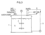
- FIGURE 3 is a schematic sectional view of the oxidizing apparatus as used in EXAMPLE 3;
- FIGURE 4 is a graph showing the efficiency of iron polysulfate production (or the rate of oxidation) as achieved in EXAMPLE 1; and
- FIGURE 5 is a graph showing the ratio of oxidation as obtained in EXAMPLE 1 from the treatment of a liquid resulting from the desulfurization of smoke.
- Description will be made of the oxidizing system of this invention with reference to FIGURE 1. FIGURE 1 shows an oxidizing apparatus comprising a
reaction vessel 1 of the closed construction containing astirrer 2 driven by a motor M. Thevessel 1 has aliquid supply port 3 through which theliquid 4 to be treated can be introduced into thevessel 1. Abypass 5 is connected to thevessel 1 and is provided with a pump P for circulating the liquid. Thevessel 1 and thebypass 5 form a closed circuit. The closed circuit is provided with anejector 6 at the top of thevessel 1 or in thebypass 5. - The
ejector 6 comprises anozzle 7, and aninlet 8 through which an oxidizing agent (e.g. oxygen, O₂) is supplied into thenozzle 7. Thenozzle 7 forms a rapid jet stream of the liquid to be treated, and the oxidizing agent entering theinlet 8 is supplied into the jet stream. This enables the efficient mixing of oxygen (and an oxidizing catalyst) with the matter to be oxidized which the liquid contains, and thereby an efficient oxidizing reaction, as well as a reduction in the amount of the oxidizing agent which is required. - The catalyst may be mixed in the oxidizing agent which is supplied into the
ejector 6 through itsinlet 8. The supply of the catalyst with the oxidizing agent into the jet stream in theejector 6 enables a still more efficient oxidizing reaction, as well as a reduction in the amount of the catalyst which is required. - If the
ejector 6 is provided at the top of thevessel 1 as shown in FIGURE 1, thevessel 1 has a vacant space above theliquid 4. The oxidizing agent is stored in the vacant space and is smoothly drawn into theejector 6 through theinlet 8 by a negative pressure created by the jet stream formed in theejector 6. Theejector 6 has a lower end which is usually so positioned as to be dipped in the liquid, though it may alternatively be located in the space above the liquid. - If the
ejector 6 is provided in thebypass 5, it is necessary to provide at least an ejector portion in the vicinity of theinlet 8 with a vacant space into which the oxidizing agent can be supplied. The vacant space in theejector 6 may be connected with the vacant space in thevessel 1. - Although the apparatus of FIGURE 1 has only one ejector, it is also possible to provide two or more ejectors. Although FIGURE 1 shows a batch system having a single closed oxidizing circuit, it is also possible to construct a continuous system having a plurality of closed circuits connected to one another.
- The
liquid supply port 3 is of the closable construction. Thevessel 1 has also a port through which the oxidizing agent (and the catalyst g) is supplied into thevessel 1, and a port through which the liquid which has been treated is discharged from thevessel 1. All of these ports are of the closable construction. - The catalyst may be appropriately selected to suit the matter to be oxidized.
- The invention will now be described more specifically with reference to a number of examples. It is, however, to be understood that this invention is not limited to these examples, but is applicable to various other systems for oxidizing treatment.
- This example was directed to the manufacture of iron polysulfate as a coagulant by employing the apparatus as shown in FIGURE 1.
- An appropriate amount of a mixture of ferrous sulfate (FeSO₄·7H₂O), waste sulfuric acid (H₂SO₄) and water (H₂O) was supplied into the reaction vessel as the liquid to be treated. The sulfuric acid was employed in an amount giving a molar ratio of SO₄⁻²/Fe⁺² which was larger than 1.0, but smaller than 1.5. The vacant space in the closed vessel was purged with oxygen. The pump was started to circulate the liquid through the bypass, so that the ejector might form a continuous jet stream of the liquid. Oxygen was supplied in the amount equal to one-third of the equivalent of Fe⁺², while at the same time, sodium nitrite, NaNO₂, was supplied at a rate of 0.8 kg/m³ per hour as an oxidizing catalyst.
- As a result, the ferrous sulfate in the liquid flowing down the ejector was oxidized to form viscous iron polysulfate below the ejector. The oxidizing reaction which took place showed an efficiency which was about four times higher than what could be achieved in the production of iron polysulfate by the conventional system, as is obvious from FIGURE 4.
- Iron polysulfate is expressed by the formula [Fe₂(OH)n·(SO₄)₃₋

- It is economical to use NO, NO₂ or other nitrogen oxide as the catalyst.
- The procedures of EXAMPLE 1 were followed for treating a liquid resulting from the desulfurization of smoke. The system of this invention showed a ratio of oxidation which was about twice higher than what could be obtained by the conventional system.
- The procedures of EXAMPLE 1 wwere followed for producing iron polysulfate, except that the apparatus was modified as shown in FIGURE 2. The modified apparatus had two
bypasses 5 connected to the reaction vessel and each having an outlet opening toward the vacant space in the top portion of the vessel, and twoejectors 6 each connected to one of thebypasses 5. - The modified system showed a reaction efficiency which was about twice higher than what had been obtained in EXAMPLE 1.
- The procedures of EXAMPLE 1 were followed for producing iron polysulfate, except that the apparatus was modified as shown in FIGURE 3, i.e. the
ejector 6 was provided in thebypass 5 outside thereaction vessel 1. The modified system showed a reaction efficiency which was comparable to what had been obtained in EXAMPLE 1. - Although the invention has been described with reference to the examples directed to the manufacture of iron polysulfate, it is easy to produce a double salt of iron polychloride and iron sulfate, too, if the liquid to be treated further contains a solution of iron chloride.
- This invention makes it possible to accomplish an efficient and economical oxidizing treatment of a liquid by employing a compact system defining a closed circuit provided with an ejector for forming a jet stream of the liquid into which an oxidizing agent is supplied to cause an oxidizing reaction, as hereinabove described. Therefore, the invention is not only useful for the treatment of waste water, such as from factories, but also applicable to a system for making a particular product at a low cost by oxidizing a liquid.
Claims (2)
- A method for oxidizing a liquid containing matter to be oxidized in a closed circuit comprising the steps of:(a) purging a reservoir (4) in a reaction vessel (1) and a bypass (5) with said liquid,(b) providing oxygen in a gas space above the reservoir (4) to oxidize said matter,(c) providing sodium nitrite to be drawn into an ejector (6) in or at the end of said bypass (5) at the top portion of said vessel (1),(d) circulating said liquid through said ejector (6) in or at the end of said bypass (5) at the top portion of said vessel (1) to form a jet stream of said liquid whereby the oxygen and sodium nitrite are drawn into said jet stream, so that said oxygen and sodium nitrite are mixed with said oxidizable matter, thereby oxidizing said oxidizable matter,(e) feeding said jet stream of said mixture to said reservoir (4), thereby stirring said reservoir with a stirring means (2) and with said jet stream to accelerate the oxidation of said oxidizable matter and(f) circulating a mixture of said liquid and any unreacted oxygen and sodium nitrite through said bypass (5) for it to be ejected through the ejector (6) again.
- The method according to claim 1 wherein said liquid is selected from the group consisting of:
a mixture of ferrous sulfate, waste sulfuric acid and water;
a mixture of ferrous sulfate, waste sulfuric acid, iron chloride and water;
and a liquid containing sulfur as a result of the desulfurisation of smoke containing sulfur compounds.
Priority Applications (1)
| Application Number | Priority Date | Filing Date | Title |
|---|---|---|---|
| AT90101033T ATE103884T1 (en) | 1989-01-20 | 1990-01-18 | PROCESSES FOR THE OXIDATION OF LIQUID. |
Applications Claiming Priority (2)
| Application Number | Priority Date | Filing Date | Title |
|---|---|---|---|
| JP11162/89 | 1989-01-20 | ||
| JP1011162A JPH02191541A (en) | 1989-01-20 | 1989-01-20 | Oxidation of liquid and equipment thereof |
Publications (2)
| Publication Number | Publication Date |
|---|---|
| EP0379204A1 EP0379204A1 (en) | 1990-07-25 |
| EP0379204B1 true EP0379204B1 (en) | 1994-04-06 |
Family
ID=11770343
Family Applications (1)
| Application Number | Title | Priority Date | Filing Date |
|---|---|---|---|
| EP90101033A Expired - Lifetime EP0379204B1 (en) | 1989-01-20 | 1990-01-18 | Liquid oxidizing method and apparatus |
Country Status (7)
| Country | Link |
|---|---|
| EP (1) | EP0379204B1 (en) |
| JP (1) | JPH02191541A (en) |
| KR (1) | KR940001420B1 (en) |
| AT (1) | ATE103884T1 (en) |
| CA (1) | CA2007974C (en) |
| DE (1) | DE69007805T2 (en) |
| FI (1) | FI102889B1 (en) |
Families Citing this family (14)
| Publication number | Priority date | Publication date | Assignee | Title |
|---|---|---|---|---|
| US5194241A (en) * | 1988-12-08 | 1993-03-16 | Eaglebrook International, Inc. | Manufacture of hydroxylated ferric sulphate compound |
| CA1336856C (en) * | 1988-12-08 | 1995-09-05 | Jaroslav R. Derka | Manufacture of hydroxylated ferric sulphate compounds |
| JPH0810780A (en) * | 1994-06-29 | 1996-01-16 | Hajime Honda | Oxidizing device for water treatment using venturi pipe |
| JP3660709B2 (en) * | 1995-03-14 | 2005-06-15 | エア・ウォーター薬化株式会社 | Apparatus for producing ferric sulfate solution and basic ferric sulfate solution |
| JP3686446B2 (en) * | 1995-03-14 | 2005-08-24 | エア・ウォーター薬化株式会社 | Ferric sulfate solution and method for producing basic ferric sulfate solution |
| US6139755A (en) * | 1997-06-14 | 2000-10-31 | Marte; Walter | Oxidation method, nozzle system and sewage treatment plant |
| JP3586557B2 (en) * | 1998-04-02 | 2004-11-10 | 株式会社杉田製線 | Method for efficiently producing ferric polysulfate |
| JP3586563B2 (en) * | 1998-04-21 | 2004-11-10 | 株式会社杉田製線 | Method for producing ferric polysulfate efficiently |
| JP3482132B2 (en) * | 1998-07-27 | 2003-12-22 | 株式会社杉田製線 | Ferric polysulfate production equipment |
| JP2002239565A (en) * | 2001-02-19 | 2002-08-27 | Nagaoka International Corp | Method for removing iron from groundwater pumped up by dewater method |
| JP4815082B2 (en) * | 2001-09-28 | 2011-11-16 | 日鉄鉱業株式会社 | Treatment method of iron-containing sulfuric acid solution |
| RU2294918C1 (en) * | 2005-12-20 | 2007-03-10 | Андрей Леонидович Загорский | Mixture of poly-(1,4-dihydroxy)-phenylenes (polyhydroquinones) |
| JP4947640B2 (en) * | 2007-01-31 | 2012-06-06 | 日新製鋼株式会社 | Waste acid solution treatment method |
| JP6931270B2 (en) * | 2016-05-31 | 2021-09-01 | 三菱ケミカルエンジニアリング株式会社 | A gas-liquid reaction device equipped with a micro-nano bubble generator and a gas-liquid reaction method using this gas-liquid reaction device. |
Family Cites Families (5)
| Publication number | Priority date | Publication date | Assignee | Title |
|---|---|---|---|---|
| GB661058A (en) * | 1949-12-30 | 1951-11-14 | Joseph Thompson Brown | Improvements relating to the treatment of gas works ammoniacal liquor and other effluents |
| JPS511677A (en) * | 1974-06-26 | 1976-01-08 | Takenori Nakagaki | |
| JPS5118298A (en) * | 1974-08-06 | 1976-02-13 | Dowa Mining Co | HEIKAIROHOSHIKINYORU DAIICHITETSUIONNO SANKAHO |
| FR2317231A1 (en) * | 1975-07-09 | 1977-02-04 | Pechiney Aluminium | PROCESS FOR OXIDIZING FERROUS SULPHATE IN AQUEOUS SULFURIC SOLUTION |
| DE2843634A1 (en) * | 1978-10-06 | 1980-04-10 | Daimler Benz Ag | Car window lowering fixture to operating arm - uses tightening screw penetrating glass with play and elastic distance pieces |
-
1989
- 1989-01-20 JP JP1011162A patent/JPH02191541A/en active Pending
-
1990
- 1990-01-09 KR KR1019900000178A patent/KR940001420B1/en not_active Expired - Lifetime
- 1990-01-17 CA CA002007974A patent/CA2007974C/en not_active Expired - Lifetime
- 1990-01-18 EP EP90101033A patent/EP0379204B1/en not_active Expired - Lifetime
- 1990-01-18 FI FI900291A patent/FI102889B1/en active IP Right Grant
- 1990-01-18 DE DE69007805T patent/DE69007805T2/en not_active Expired - Fee Related
- 1990-01-18 AT AT90101033T patent/ATE103884T1/en not_active IP Right Cessation
Also Published As
| Publication number | Publication date |
|---|---|
| CA2007974C (en) | 1996-12-31 |
| FI102889B (en) | 1999-03-15 |
| DE69007805T2 (en) | 1994-07-28 |
| ATE103884T1 (en) | 1994-04-15 |
| CA2007974A1 (en) | 1990-07-20 |
| FI102889B1 (en) | 1999-03-15 |
| KR940001420B1 (en) | 1994-02-23 |
| FI900291A0 (en) | 1990-01-18 |
| DE69007805D1 (en) | 1994-05-11 |
| EP0379204A1 (en) | 1990-07-25 |
| KR900011672A (en) | 1990-08-01 |
| JPH02191541A (en) | 1990-07-27 |
Similar Documents
| Publication | Publication Date | Title |
|---|---|---|
| EP0379204A1 (en) | Liquid oxidizing method and apparatus | |
| CA1241774A (en) | Effluent treatment | |
| US4784775A (en) | Removal of hydrogen sulfide from sour water | |
| US5985223A (en) | Removal of NOx and SOx emissions form pickling lines for metal treatment | |
| US5126118A (en) | Process and apparatus for removal of H2 S with separate absorber and oxidizer and a reaction chamber therebetween | |
| US3617559A (en) | Neutralization of ferrous iron-containing acid wastes | |
| US5286389A (en) | Removal of hydrogen sulfide from sour water | |
| WO1996000191A1 (en) | Anaerobic removal of sulphur compounds from waste water | |
| US5266297A (en) | Liquid oxidizing method and apparatus | |
| CN112978996A (en) | Method for deeply treating organic matters and ammonia nitrogen in titanium dioxide production wastewater | |
| JP3403348B2 (en) | Treatment method for nitrogen-containing wastewater | |
| JPH0336598B2 (en) | ||
| JP2000016816A (en) | Method for efficiently producing high-purity ferric polysulfate | |
| JP2003181476A (en) | Method for decomposing chelating agent | |
| RU2031858C1 (en) | Method of sewage treatment from dyes | |
| JP2001259688A (en) | Waste liquid treatment method | |
| JP4862234B2 (en) | Method for treating waste water containing hydrazine and chelating organic compound | |
| JP3575504B2 (en) | Treatment of colored wastewater | |
| JPH02102787A (en) | Treatment of waste pickling liquid | |
| JPH0466638B2 (en) | ||
| Owens | Iron and Manganese Removal by Split‐Flow Treatment | |
| DE2516342A1 (en) | Catalytic oxidn. of aq. (bi)sulphite soln. to (bi)sulphate - using ferric (and ferrous) ions as catalyst, avoiding toxicity problems | |
| JPS59127634A (en) | Treatment of exhaust gas containing copper component and sulfur dioxide gas | |
| KR930004188B1 (en) | Reduction of chemical oxygen demand (COD) in wastewater using urea | |
| RU1787136C (en) | Method of coagulator preparation from spent pickling solution |
Legal Events
| Date | Code | Title | Description |
|---|---|---|---|
| PUAI | Public reference made under article 153(3) epc to a published international application that has entered the european phase |
Free format text: ORIGINAL CODE: 0009012 |
|
| AK | Designated contracting states |
Kind code of ref document: A1 Designated state(s): AT DE GB IT SE |
|
| 17P | Request for examination filed |
Effective date: 19900608 |
|
| 17Q | First examination report despatched |
Effective date: 19911108 |
|
| GRAA | (expected) grant |
Free format text: ORIGINAL CODE: 0009210 |
|
| AK | Designated contracting states |
Kind code of ref document: B1 Designated state(s): AT DE GB IT SE |
|
| REF | Corresponds to: |
Ref document number: 103884 Country of ref document: AT Date of ref document: 19940415 Kind code of ref document: T |
|
| REF | Corresponds to: |
Ref document number: 69007805 Country of ref document: DE Date of ref document: 19940511 |
|
| ITF | It: translation for a ep patent filed | ||
| EAL | Se: european patent in force in sweden |
Ref document number: 90101033.0 |
|
| PLBE | No opposition filed within time limit |
Free format text: ORIGINAL CODE: 0009261 |
|
| STAA | Information on the status of an ep patent application or granted ep patent |
Free format text: STATUS: NO OPPOSITION FILED WITHIN TIME LIMIT |
|
| 26N | No opposition filed | ||
| REG | Reference to a national code |
Ref country code: GB Ref legal event code: IF02 |
|
| PGFP | Annual fee paid to national office [announced via postgrant information from national office to epo] |
Ref country code: SE Payment date: 20070108 Year of fee payment: 18 |
|
| PGFP | Annual fee paid to national office [announced via postgrant information from national office to epo] |
Ref country code: GB Payment date: 20070109 Year of fee payment: 18 |
|
| PGFP | Annual fee paid to national office [announced via postgrant information from national office to epo] |
Ref country code: AT Payment date: 20070111 Year of fee payment: 18 |
|
| PGFP | Annual fee paid to national office [announced via postgrant information from national office to epo] |
Ref country code: DE Payment date: 20070227 Year of fee payment: 18 |
|
| PGFP | Annual fee paid to national office [announced via postgrant information from national office to epo] |
Ref country code: IT Payment date: 20070628 Year of fee payment: 18 |
|
| EUG | Se: european patent has lapsed | ||
| GBPC | Gb: european patent ceased through non-payment of renewal fee |
Effective date: 20080118 |
|
| PG25 | Lapsed in a contracting state [announced via postgrant information from national office to epo] |
Ref country code: DE Free format text: LAPSE BECAUSE OF NON-PAYMENT OF DUE FEES Effective date: 20080801 |
|
| PG25 | Lapsed in a contracting state [announced via postgrant information from national office to epo] |
Ref country code: AT Free format text: LAPSE BECAUSE OF NON-PAYMENT OF DUE FEES Effective date: 20080118 |
|
| PG25 | Lapsed in a contracting state [announced via postgrant information from national office to epo] |
Ref country code: GB Free format text: LAPSE BECAUSE OF NON-PAYMENT OF DUE FEES Effective date: 20080118 |
|
| PG25 | Lapsed in a contracting state [announced via postgrant information from national office to epo] |
Ref country code: SE Free format text: LAPSE BECAUSE OF NON-PAYMENT OF DUE FEES Effective date: 20080119 |
|
| PG25 | Lapsed in a contracting state [announced via postgrant information from national office to epo] |
Ref country code: IT Free format text: LAPSE BECAUSE OF NON-PAYMENT OF DUE FEES Effective date: 20080118 |