EP0379068A2 - Optical molding method and apparatus - Google Patents
Optical molding method and apparatus Download PDFInfo
- Publication number
- EP0379068A2 EP0379068A2 EP90100525A EP90100525A EP0379068A2 EP 0379068 A2 EP0379068 A2 EP 0379068A2 EP 90100525 A EP90100525 A EP 90100525A EP 90100525 A EP90100525 A EP 90100525A EP 0379068 A2 EP0379068 A2 EP 0379068A2
- Authority
- EP
- European Patent Office
- Prior art keywords
- aperture
- container
- light
- light flux
- resin
- Prior art date
- Legal status (The legal status is an assumption and is not a legal conclusion. Google has not performed a legal analysis and makes no representation as to the accuracy of the status listed.)
- Withdrawn
Links
Images

Classifications
-
- B—PERFORMING OPERATIONS; TRANSPORTING
- B29—WORKING OF PLASTICS; WORKING OF SUBSTANCES IN A PLASTIC STATE IN GENERAL
- B29C—SHAPING OR JOINING OF PLASTICS; SHAPING OF MATERIAL IN A PLASTIC STATE, NOT OTHERWISE PROVIDED FOR; AFTER-TREATMENT OF THE SHAPED PRODUCTS, e.g. REPAIRING
- B29C64/00—Additive manufacturing, i.e. manufacturing of three-dimensional [3D] objects by additive deposition, additive agglomeration or additive layering, e.g. by 3D printing, stereolithography or selective laser sintering
- B29C64/10—Processes of additive manufacturing
- B29C64/106—Processes of additive manufacturing using only liquids or viscous materials, e.g. depositing a continuous bead of viscous material
- B29C64/124—Processes of additive manufacturing using only liquids or viscous materials, e.g. depositing a continuous bead of viscous material using layers of liquid which are selectively solidified
- B29C64/129—Processes of additive manufacturing using only liquids or viscous materials, e.g. depositing a continuous bead of viscous material using layers of liquid which are selectively solidified characterised by the energy source therefor, e.g. by global irradiation combined with a mask
- B29C64/135—Processes of additive manufacturing using only liquids or viscous materials, e.g. depositing a continuous bead of viscous material using layers of liquid which are selectively solidified characterised by the energy source therefor, e.g. by global irradiation combined with a mask the energy source being concentrated, e.g. scanning lasers or focused light sources
-
- B—PERFORMING OPERATIONS; TRANSPORTING
- B29—WORKING OF PLASTICS; WORKING OF SUBSTANCES IN A PLASTIC STATE IN GENERAL
- B29C—SHAPING OR JOINING OF PLASTICS; SHAPING OF MATERIAL IN A PLASTIC STATE, NOT OTHERWISE PROVIDED FOR; AFTER-TREATMENT OF THE SHAPED PRODUCTS, e.g. REPAIRING
- B29C35/00—Heating, cooling or curing, e.g. crosslinking or vulcanising; Apparatus therefor
- B29C35/02—Heating or curing, e.g. crosslinking or vulcanizing during moulding, e.g. in a mould
- B29C35/08—Heating or curing, e.g. crosslinking or vulcanizing during moulding, e.g. in a mould by wave energy or particle radiation
- B29C35/0805—Heating or curing, e.g. crosslinking or vulcanizing during moulding, e.g. in a mould by wave energy or particle radiation using electromagnetic radiation
- B29C2035/0833—Heating or curing, e.g. crosslinking or vulcanizing during moulding, e.g. in a mould by wave energy or particle radiation using electromagnetic radiation using actinic light
Definitions
- the present invention relates to optical molding method and apparatus for optically molding a cured object having a desired configuration by radiating light on a photocurable resin. More particularly, the present invention relates to a method of optically molding an cured object by radiating a light flux on a photocurable resin in a container while scanning the resin by the light flux through an aperture provided on the container and an apparatus for optically molding a cured object by radiating light on a photocurable resin in a container through an aperture provided on the container.
- Optical molding methods for optically producing a target object by repeating the process of radiating a light flux on a photocurable resin so as to cure the irradiated portion and extend the cured portion continuously in the horizontal direction, supplying a photocurable resin on the upper side of the cured portion and radiating a light flux on the resin so as to also extend the cured portion continuously in the vertical direction are known as disclosed in, for example, Japanese Patent Laid-Open Nos. 247515/1985, 35966/1987 and 10140/1987.
- a method of using a mask in place of the scanning by a light flux is also known.
- One of these methods adopts an apparatus including a container having an aperture on the bottom surface or a side surface thereof, a device for radiating a light flux through the aperture, and a base provided in the container in such a manner as to be movable away from the aperture.
- This optical molding method will be explained with reference to Fig. 2.
- a photocurable resin 12 is accommodated in a container 11.
- an aperture 13 made of a light transmitting plate such as a silica glass plate is provided on the bottom surface of the container 11.
- An optical system (light radiation device) is provided which is composed of a light emitting portion 15 with a built-in lens for radiating a light flux 14 onto the aperture 13, an optical fiber 16, an X-Y table 17 for moving the light emitting portion 15 in the X-Y direction in the horizontal plane, wherein X and Y are two directions orthogonal to each other, and a light source 20.
- a base 21 is disposed in the container 11 so as to be lifted and lowered by an elevator 22.
- the X-Y table 17 and the elevator 22 are controlled by a computer 23.
- the base 21 is first located slightly above the aperture 13 and the light flux 14 scans a horizontal section (the portion corresponding to the bottom surface or the upper surface, in this case) of the target object.
- the scanning operation is carried out by moving the X-Y table 17 controlled by the computer.
- the base 21 is slightly lifted and an uncured photocurable resin is poured between the cured object (cured layer) 24 and the base 21, and light is radiated in the same way as above.
- the cured object having the intended configuration is obtained as a laminate.
- the scanning operation of the light flux 14 is carried out by moving the X-Y table 17, but it is possible to adopt an optical system instead in which the light emitted from the light source and reflected by a mirror (not shown) is converged by the lens so as to radiate the light onto the photocurable resin.
- the scanning operation of the light flux 14 is carried out by rotating the mirror.
- the cured object 24 is produced by the scanning of the light flux 14 in the apparatus shown in Fig. 2, for example, a mask 26 provided with slits 25 and having a configuration which corresponds to the section of the target object may be used instead, as shown in Fig. 3.
- the reference numeral 27 represents a parallel light flux.
- the other reference numerals in Fig. 3 represent the corresponding elements to those in Fig. 2.
- a resin coat layer 13a of, e.g., a fluorine plastic is formed on the surface of the aperture 13 on the inner wall side of the of container in the prior art.
- the resin coat layer has a low adhesion with the cured object 24, which is a cured photocurable resin, so that when the base 21 is lifted, the cured object 24 is easily separated from the aperture 13 and is constantly kept in the state of being adhered to the base 21.
- PTFE polyethylene tetrafluoride
- the light flux 14 When the light flux 14 is radiated from the light emitting portion 15 in the above-described way, the light flux 14 is conventionally focused by the lens (not shown) of the light emitting portion 15 so that the focal point F is in the resin coating layer 13a.
- Such deterioration of the resin coating layer 13a is apt to be caused in the case of locally radiating the light flux 14 at the same portion for a long time in succession such as the case of growing a long cylindrical member in the longitudinal direction of the cylinder by laminating discal cured objects.
- the resin coating layer 13a formed on the surface of the aperture 13 on the inner wall side of the container 11 is required to have the following characteristics:
- the resin coating layer 13a Since it is necessary to transmit light such as ultraviolet light through the resin coating layer 13a, the resin coating layer 13a must have a light transmission property with respect to ultraviolet light (ultraviolet light used has a wavelength of 325 nm).
- the resin coating layer 13a has light resistance and durability.
- the resin coating layer 13a When the resin coating layer 13a is exposed to the light flux 14 for a long time, the resin coating layer 13a is deteriorated or minute protrusions are produced on the surface of the resin coating layer 13a, so that the adhesion between the cured object 24 and the resin coating layer 13a increases, thereby involving a fear of the cured object 24 being separated from the base 21 at the time of lifting the base 21, as described above. For this reason, the resin coating layer 13a is required to be stable with respect to light and excellent in durability.
- the resin coating layer 13a is stable with respect to the photocurable resin 12.
- PTFE which is conventionally frequently adopted, has excellent light resistance and a small adhesion with the cured object, but it is inferior in transparency and has a low ultraviolet light transmittance.
- another fluorine plastic ethylene tetrafluoride - perfluoroalkylvinyl ether copolymer (hereinunder referred to as "PFA") has a light transmission property but the adhesion with the cured object is large.
- an optical molding method comprising the step of laminating a multiplicity of cured layers of a photocurable resin each of which corresponds to a section of a target object by radiating a light flux from an aperture provided with a resin coating layer in a container such that the focal point of the light flux is a point except a point in the resin coating layer and gradually moving a base away from the aperture.
- the concentration of the radiation of the light flux on the resin coating layer of the aperture is avoided.
- the local deterioration of the resin coating layer is prevented.
- an optical molding method comprising the step of laminating a multiplicity of cured layers of a photocurable resin each of which corresponds to a section of a target object by radiating a light flux from an aperture provided with a resin coating layer in a container and gradually moving a base away from the aperture and moving the aperture in the direction of the plane of the aperture in the state in which a cured object is away from the aperture.
- the concentration of the successive radiation of the light flux on the same place of the aperture is avoided.
- the deterioration of the resin coating layer is prevented.
- an optical molding apparatus for producing an object by radiating light onto a photocurable resin in a container from an aperture so as to form a cured object on the surface of a base in the container or a cured object thereon, characterized in that an ethylene tetrafluoride - propylene hexafluoride copolymer (hereinunder referred to as "FEP") coating film is formed on the surface of the aperture on the inner wall side of the container.
- FEP ethylene tetrafluoride - propylene hexafluoride copolymer
- the resin coating film formed on the surface of the aperture has an excellent property.
- an optical molding apparatus for producing an object by radiating light onto a photocurable resin in a container from an aperture so as to form a cured object on the surface of a base in the container or a cured object thereon, characterized in that a reflectionless coating is applied to at least one surface of the aperture.
- the reflection of light on the surface of the aperture is reduced and the loss of the light energy is therefore reduced.
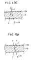
- Figs. 1a and 1b are enlarged sectional views of the aperture in the apparatus for executing an optical molding method of a first embodiment of the present invention.
- the focal point F is preferably not less than 0.5 mm, more preferably not less than 1 mm apart from the resin coating layer 13a.
- the focal point F is excessively apart from the resin coating layer 13a, there is a fear of the side end surface of the cured object obtained being deficient in the sharpness, thereby producing an object losing its trim shape.
- the distance between the focal point F and the resin coating layer 13a is slightly different depending on the focal length of the lens provided in the light emitting portion 15, the focal point F is preferably within a distance of 3 mm, more preferably 2 mm from the resin coating layer 13a.
- the aperture 13 is provided on the bottom surface of the container 11 and light is radiated from below the container 11.
- the aperture 13 may be provided on a side surface of the container 11 and light is radiated from the side surface of the container 11. In this case, the base 21 is gradually moved sideways in the production process.
- the scanning operation of the light flux 14 is carried out by moving the X-Y table 17 but it is possible to adopt an optical system instead in which the light emitted from the light source and reflected by a mirror (not shown) is thereafter converged by the lens so as to radiate the light onto the photocurable resin.
- the scanning operation of the light flux 14 is carried out by rotating the mirror.
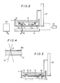
- Fig. 5 is a vertical sectional view of an optical molding apparatus which is suitable for executing the second embodiment of the present invention.
- the container 11 is in the shape of a circle in plan view.
- the aperture 13 is attached to the bottom surface of the container 11 by a ring frame 30.
- the frame 30 is secured to the flange portion 11a of the container 11 by bolts 31, and the outer periphery of the aperture 13 is clamped between the inner peripheral portion of the frame 30 and the flange portion 11a of the container 11.
- An annular rack 32 is secured to the bottom surface of the frame 30.
- the frame 30 is rotatably supported by a support block 35 on a machine base 34 through a vertical pair of thrust bearings, and the container 11 is rotatable around the axis A in the horizontal plane.
- a motor 36 is placed on the machine base 34, and a pinion 37 is secured to the rotary shaft of the motor 36.
- the pinion 37 is intermeshed with the rack 32.
- the X-Y table 17 is provided in such a manner as to face the bottom surface of the aperture 13.
- the X-Y table 17 freely moves the light emitting portion 15 in the horizontal plane.
- Light such as a laser beam is supplied from the light source 20 (not shown in Fig. 5) to the light emitting portion 15 through the optical fiber 16.
- the base 21 is disposed in the container 11 in such a manner as to be allowed to be vertically moved by the elevator 22.
- the light source 20, the elevator 22, the motor 36 and the X-Y table 17 are controlled by the computer 23.
- the upper surface of the aperture 13 is provided with the resin coating layer 13a of a fluorine plastic.
- the base 21 is first moved away from the aperture 13 by a predetermined distance (for example, about 0.1 to 1 mm), and light is then radiated so as to form a first cured layer 24.
- a predetermined distance for example, about 0.1 to 1 mm
- the motor 36 is driven to rotate the container 11 around the axis A by a predetermined angle. Thereafter, light is radiated again to form a second cured layer 24.
- the container 11 is rotated and a third cured layer 24 is formed. This process is successively repeated.
- the laminate of the cured layers 24 is removed from the base 21 and subjected to finishing, if necessary, thereby producing the target object.
- the local concentration of light radiation on the resin coating layer 13a of the aperture 13 is avoided. More specifically, since the container 11 is rotated after the formation of the n-th (n is a natural number) cured layer 24 and before the formation of the (n + 1)th layer 25, even if the n-th layer and the (n + 1)th layer have the same configuration and are formed at the same position with respect to the base 21, the light emitted from the light emitting portion 15 passes different portions of the aperture 13 for the n-th layer and for the (n + 1)th layer. However, when the n-th layer and the (n + 1)th layer are circular layers which are concentric with respect to the axis A and have the same diameter, the light passes the same portion of the aperture 13. In this case, the X-Y table 17 is disposed such that the center thereof is eccentric with the axis of the container 11.
- the container 11 is a circular tank in this embodiment, it may be a polygonal tank such as triangle, rectangular, pentagonal and hexagonal tanks.
- the container is rotated between the formation of the n-th layer and the formation of the (n + 1)th layer in this embodiment, it is possible not to rotate the container 11 during the formation of a plurality of cured layers and to rotate the container 11 after the formation of the plurality of cured layers.
- the aperture 13 may be moved in the two-dimensional direction in the plane of the aperture in place of being rotated in the plane of the aperture.
- the aperture 13 may be manually moved by an operator or the like in place of a motor.
- the aperture 13 is provided on the bottom surface of the container 11 and light is radiated from below the container 11 in this embodiment, but the aperture 13 may be provided on a side surface of the container 11 and light is radiated from the side surface of the container 11. In this case, the base 21 is gradually moved sideways in the molding process.
- the scanning operation of the light flux 14 is carried out by moving the X-Y table 17, but it is possible to adopt an optical system instead in which the light emitted from the light source and reflected by a mirror (not shown) is converged by the lens so as to radiate the light onto the photocurable resin. In this case, the scanning operation of the light flux 14 is carried out by rotating the mirror.
- the cured object 24 is produced by the scanning of the light flux 14 in this embodiment, for example, a mask 16 provided with slits 25 and having a configuration which corresponds to the section of the target object may be used instead, as shown in Fig. 3.
- the aperture 13 is also moved in the plane of the aperture, if necessary.
- the deterioration of the resin coating layer of the aperture is prevented and the durability of the optical molding apparatus is enhanced.
- addition since the releasability of the cured object from the resin coating layer is improved, a smooth optical molding operation is enabled.
- An optical molding apparatus of a third embodiment of the present invention is the same as the optical molding apparatuses shown in Figs. 2 and 3 except an FEP coating film is formed as the resin coating layer 13a.
- FEP which has the following excellent properties, is optimum among various fluorine plastics as the resin for the coating film of an optical molding apparatus.
- PTFE, PFA and FEP have the following structural formulas, respectively.
- the dissociation energies (Kcal/mol (25°C)) of chief interatomic bonds are as follows: C - C: 84 C - F: 129 C - 0: 76
- the light resistance and the durability are greatly influenced by the dissociation energy for bonding for constituting a molecule, and the larger dissociation energy a molecule has, the more excellent light resistance and durability it has.
- the adhesion of a molecule is the smaller, as the dissociation energy thereof is the larger.
- FEP which is composed of C - F bondings and C - C bondings having a large dissociation energy
- PTFE which is also composed of C - F bondings and C - C bondings
- PFE which includes a C - O bonding having a small dissociation energy
- PFE is inferior in light resistance and durability, and has a large adhesion.
- the thickness of the FEP resin coating film is too large, it is impossible to obtain a sufficient light transmittance, while if it is too small, the light resistance and the durability are insufficient and the adhesion improving effect of the resin coating is also insufficient.
- the preferable thickness of the FEP resin coating film is therefore about 5 to 100 ⁇ m.
- the resin coating film of the aperture has excellent light transmittance, light resistance and durability and a small adhesion with a cured object. It is therefore possible to pass light therethrough at a high transmittance, thereby enabling efficient molding operation.
- the deterioration of the coating film is prevented and an optical molding apparatus efficient in durability is obtained.
- smooth optical molding operation is effected.
- An optical molding apparatus of a fourth embodiment of the present invention is the same as the apparatuses shown in Figs. 2 and 3 except that a reflectionless coating is applied to one surface, preferably both surfaces of the aperture.
- the target object having the intended configuration is obtained as a laminate. Since both surfaces of the aperture 13 is subjected to reflectionless coating in the molding process, the amount of light flux 14 reflected on the surface of the aperture 13 is very small, and light energy loss is scarcely produced. A reflectionless coating applied merely to one surface of the aperture 13 also has the light reflection preventive effect in its own way.
- various coatings such as a magnesium fluoride coating may be adopted.
- the aperture 13 is provided on the bottom surface of the container 11 and light is radiated from below the container 11 in the apparatus shown in Fig. 2, but the aperture 13 may be provided on a side surface of the container 11 and light is radiated from the side surface of the container 11. In this case, the base 21 is gradually moved sideways in the molding process.
- the reflection loss of the light radiated onto the photocurable resin is very small.
- the cost of the electric power is therefore reduced and the curing speed is increased and hence the molding time is shortened without increasing the power of the light source.
- the aperture 13 is preferably made of a material having a light transmitting property with respect to the light flux 14 and necessary strength and corrosion resistance. If the light flux 14 is ultraviolet light, a silica glass plate is optimum.
- a fluorine plastic is preferably used, more preferably an ethylene tetrafluoride - propylene hexafluoride copolymer is used in the same way as in the third embodiment.
- An ethylene tetrafluoride - propylene hexafluoride copolymer has a high transmittance with respect to ultraviolet light and is slow to be deteriorated by ultraviolet light.
- the adhesion of the photocurable resin with the cured object is small.
- various resins which are cured by light irradiation are usable.
- modified polyurethane methacrylate, origo-ester acrylate, urethane acrylate, epoxy acrylate, photosensitive polyimide and aminoalkyd will be cited.
- the light various kinds of lights such as visible light and ultraviolet light may be used in accordance with the photocurable resin used.
- the light may be used in the form of ordinary light, but if it is used as a laser beam, it is possible to enhance the energy level, shorten the molding time and enhance the molding accuracy by utilizing the good condensing property.
- the FEP coating resin film of the third embodiment has a high mechanical strength. excellent light transmittance, and a small adhesion, so that it is optimum as the coating film of the aperture.
Abstract
Description
- The present invention relates to optical molding method and apparatus for optically molding a cured object having a desired configuration by radiating light on a photocurable resin. More particularly, the present invention relates to a method of optically molding an cured object by radiating a light flux on a photocurable resin in a container while scanning the resin by the light flux through an aperture provided on the container and an apparatus for optically molding a cured object by radiating light on a photocurable resin in a container through an aperture provided on the container.
- Optical molding methods for optically producing a target object by repeating the process of radiating a light flux on a photocurable resin so as to cure the irradiated portion and extend the cured portion continuously in the horizontal direction, supplying a photocurable resin on the upper side of the cured portion and radiating a light flux on the resin so as to also extend the cured portion continuously in the vertical direction are known as disclosed in, for example, Japanese Patent Laid-Open Nos. 247515/1985, 35966/1987 and 10140/1987. A method of using a mask in place of the scanning by a light flux is also known.
- One of these methods adopts an apparatus including a container having an aperture on the bottom surface or a side surface thereof, a device for radiating a light flux through the aperture, and a base provided in the container in such a manner as to be movable away from the aperture. This optical molding method will be explained with reference to Fig. 2.
- In Fig. 2, a
photocurable resin 12 is accommodated in acontainer 11. On the bottom surface of thecontainer 11, anaperture 13 made of a light transmitting plate such as a silica glass plate is provided. An optical system (light radiation device) is provided which is composed of a light emitting portion 15 with a built-in lens for radiating alight flux 14 onto theaperture 13, anoptical fiber 16, an X-Y table 17 for moving the light emitting portion 15 in the X-Y direction in the horizontal plane, wherein X and Y are two directions orthogonal to each other, and alight source 20. - A
base 21 is disposed in thecontainer 11 so as to be lifted and lowered by anelevator 22. The X-Y table 17 and theelevator 22 are controlled by acomputer 23. - When a cured object is produced by the above-described apparatus, the
base 21 is first located slightly above theaperture 13 and thelight flux 14 scans a horizontal section (the portion corresponding to the bottom surface or the upper surface, in this case) of the target object. The scanning operation is carried out by moving the X-Y table 17 controlled by the computer. - After the entire surface of that horizontal section of the target object has been irradiated with light, the
base 21 is slightly lifted and an uncured photocurable resin is poured between the cured object (cured layer) 24 and thebase 21, and light is radiated in the same way as above. By repeating this process, the cured object having the intended configuration is obtained as a laminate. - In the apparatus shown in Fig. 2, the scanning operation of the
light flux 14 is carried out by moving the X-Y table 17, but it is possible to adopt an optical system instead in which the light emitted from the light source and reflected by a mirror (not shown) is converged by the lens so as to radiate the light onto the photocurable resin. In this case, the scanning operation of thelight flux 14 is carried out by rotating the mirror. - Although the cured
object 24 is produced by the scanning of thelight flux 14 in the apparatus shown in Fig. 2, for example, amask 26 provided withslits 25 and having a configuration which corresponds to the section of the target object may be used instead, as shown in Fig. 3. In Fig. 3, thereference numeral 27 represents a parallel light flux. The other reference numerals in Fig. 3 represent the corresponding elements to those in Fig. 2. - In the above-described optical molding apparatus, it is necessary to move the cured
object 24 away from theaperture 13 when lifting thebase 21. This is because if thecured object 24 is separated from thebase 21, it is impossible to continue the molding process. - For this purpose, a
resin coat layer 13a of, e.g., a fluorine plastic is formed on the surface of theaperture 13 on the inner wall side of the of container in the prior art. The resin coat layer has a low adhesion with thecured object 24, which is a cured photocurable resin, so that when thebase 21 is lifted, thecured object 24 is easily separated from theaperture 13 and is constantly kept in the state of being adhered to thebase 21. - As a fluorine plastic for the
resin coating layer 13a, polyethylene tetrafluoride (hereinunder referred to as "PTFE") is conventionally chiefly used. - When the
light flux 14 is radiated from the light emitting portion 15 in the above-described way, thelight flux 14 is conventionally focused by the lens (not shown) of the light emitting portion 15 so that the focal point F is in theresin coating layer 13a. - When the focal point F of the
light flux 14 agrees with theresin coating layer 13a in this way, if theresin coating layer 13a is exposed to thelight flux 14 for a long time, theresin coating layer 13a is deteriorated or minute protrusions are produced on the surface of theresin coating layer 13a, so that the adhesion between thecured object 24 and theresin coating layer 13a increases, thereby involving a fear of the curedobject 24 being separated from thebase 21 at the time of lifting thebase 21. Such deterioration of theresin coating layer 13a is apt to be caused in the case of locally radiating thelight flux 14 at the same portion for a long time in succession such as the case of growing a long cylindrical member in the longitudinal direction of the cylinder by laminating discal cured objects. - The
resin coating layer 13a formed on the surface of theaperture 13 on the inner wall side of thecontainer 11 is required to have the following characteristics: - Since it is necessary that the
resin coating layer 13a is easily separated from thecured object 24 when thebase 21 is lifted, it is necessary that the adhesion F₁ between theresin coating layer 13a and theaperture 13, the adhesion F₂ between theresin coating layer 13a and the curedobject 24 and the adhesion F₃ between thecured object 24 and thebase 21 have the following relationship:
F₃ > F₂
F₁ > F₂
In ordinary case, F₃ is 10 to 50 kg/cm² , and when theresin coating layer 13a is a PTFE coating film, F₂ is about 0.5 ∼ 1.5 kg/cm². - Since it is necessary to transmit light such as ultraviolet light through the
resin coating layer 13a, theresin coating layer 13a must have a light transmission property with respect to ultraviolet light (ultraviolet light used has a wavelength of 325 nm). - When the
resin coating layer 13a is exposed to thelight flux 14 for a long time, theresin coating layer 13a is deteriorated or minute protrusions are produced on the surface of theresin coating layer 13a, so that the adhesion between the curedobject 24 and theresin coating layer 13a increases, thereby involving a fear of the curedobject 24 being separated from thebase 21 at the time of lifting thebase 21, as described above. For this reason, theresin coating layer 13a is required to be stable with respect to light and excellent in durability. -
- Since the
resin coating layer 13a is constantly in contact with thephotocurable resin 12, it is naturally necessary that theresin coating layer 13a is stable with respect to thephotocurable resin 12. - No resin coating layer conventionally provided, however, fully satisfies all of the conditions 1 to 4, and the improvement has been demanded.
- For example, PTFE, which is conventionally frequently adopted, has excellent light resistance and a small adhesion with the cured object, but it is inferior in transparency and has a low ultraviolet light transmittance. On the other hand, another fluorine plastic, ethylene tetrafluoride - perfluoroalkylvinyl ether copolymer (hereinunder referred to as "PFA") has a light transmission property but the adhesion with the cured object is large.
- In addition, in a conventional optical molding apparatus, a considerable ratio of light radiated onto the photocurable resin in the container from the light radiation device is reflected on the surface of the aperture and is disadvantageously lost.
- Accordingly, it is an object of the present invention to eliminate the above-described problems in the prior art and to provide an optical molding method which is capable of preventing the deterioration of the resin coating layer of the aperture and enhancing the durability of an optical molding apparatus.
- It is another object of the present invention to provide an optical molding method which is capable of enhancing the releasability of the cured object from the resin coating layer and enabling smooth molding operation.
- It is still another object of the present invention to provide an optical molding apparatus provided with a resin coating layer on the aperture which is excellent in light transmittance, light resistance and durability, and which has a small adhesion with the cured object.
- It is a further object of the present invention to provide an optical molding apparatus which is capable of preventing the reflection of light on the surface of the aperture, thereby reducing the reflection loss of the radiated light and hence reducing the cost of electric power, increasing the curing speed and hence shortening the molding time.
- To achieve this aim, in a first aspect of the present invention, there is provided an optical molding method comprising the step of laminating a multiplicity of cured layers of a photocurable resin each of which corresponds to a section of a target object by radiating a light flux from an aperture provided with a resin coating layer in a container such that the focal point of the light flux is a point except a point in the resin coating layer and gradually moving a base away from the aperture.
- According to this method, the concentration of the radiation of the light flux on the resin coating layer of the aperture is avoided. As a result, the local deterioration of the resin coating layer is prevented.
- In a second aspect of the present invention, there is provided an optical molding method comprising the step of laminating a multiplicity of cured layers of a photocurable resin each of which corresponds to a section of a target object by radiating a light flux from an aperture provided with a resin coating layer in a container and gradually moving a base away from the aperture and moving the aperture in the direction of the plane of the aperture in the state in which a cured object is away from the aperture.
- According to this method, the concentration of the successive radiation of the light flux on the same place of the aperture is avoided. As a result, the deterioration of the resin coating layer is prevented.
- In a third aspect of the present invention, there is provided an optical molding apparatus for producing an object by radiating light onto a photocurable resin in a container from an aperture so as to form a cured object on the surface of a base in the container or a cured object thereon, characterized in that an ethylene tetrafluoride - propylene hexafluoride copolymer (hereinunder referred to as "FEP") coating film is formed on the surface of the aperture on the inner wall side of the container.
- According to this apparatus, due to the excellent property of FEP, the resin coating film formed on the surface of the aperture has an excellent property.
- In a fourth aspect of the present invention, there is provided an optical molding apparatus for producing an object by radiating light onto a photocurable resin in a container from an aperture so as to form a cured object on the surface of a base in the container or a cured object thereon, characterized in that a reflectionless coating is applied to at least one surface of the aperture.
- According to this apparatus, the reflection of light on the surface of the aperture is reduced and the loss of the light energy is therefore reduced.
- The above and other objects, features and advantages of the present invention will become clear from the following description of the preferred embodiments thereof, taken in conjunction with the accompanying drawings.
-
- Figs. 1(a) and 1(b) are explanatory enlarged sectional views of a first embodiment of an optical molding method according to the present invention;
- Figs. 2 and 3 show the structures of the apparatuses for executing the first embodiment of the present invention;
- Fig. 4 is a sectional view of the aperture of a conventional apparatus; and
- Fig. 5 shows the structure of the apparatuses for executing a second embodiment of an optical molding method according to the present invention.
- Embodiments of the present invention will be explained with reference to the accompanying drawings.
- Figs. 1a and 1b are enlarged sectional views of the aperture in the apparatus for executing an optical molding method of a first embodiment of the present invention.
- In Fig. 1(a), the
light flux 14 is focused on a point F in thecontainer 11, while in Fig. 1(b), thelight flux 14 is focused on a point F in theaperture 13. - By deviating the focal point F of the
light flux 14 from theresin coating layer 13a in this way, the concentration of the radiation of the energy oflight flux 14 on theresin coating layer 13a is avoided. As a result, the early deterioration of the resin coating layer is prevented. - In the present invention, the focal point F is preferably not less than 0.5 mm, more preferably not less than 1 mm apart from the
resin coating layer 13a. However, if the focal point F is excessively apart from theresin coating layer 13a, there is a fear of the side end surface of the cured object obtained being deficient in the sharpness, thereby producing an object losing its trim shape. Although the distance between the focal point F and theresin coating layer 13a is slightly different depending on the focal length of the lens provided in the light emitting portion 15, the focal point F is preferably within a distance of 3 mm, more preferably 2 mm from theresin coating layer 13a. - In Fig. 2, the
aperture 13 is provided on the bottom surface of thecontainer 11 and light is radiated from below thecontainer 11. Alternatively, theaperture 13 may be provided on a side surface of thecontainer 11 and light is radiated from the side surface of thecontainer 11. In this case, thebase 21 is gradually moved sideways in the production process. - In this embodiment, the scanning operation of the
light flux 14 is carried out by moving the X-Y table 17 but it is possible to adopt an optical system instead in which the light emitted from the light source and reflected by a mirror (not shown) is thereafter converged by the lens so as to radiate the light onto the photocurable resin. In this case, the scanning operation of thelight flux 14 is carried out by rotating the mirror. - An optical molding method of a second embodiment of the present invention will be explained with reference to Fig. 5.
- Fig. 5 is a vertical sectional view of an optical molding apparatus which is suitable for executing the second embodiment of the present invention.
- In this embodiment, the
container 11 is in the shape of a circle in plan view. - The
aperture 13 is attached to the bottom surface of thecontainer 11 by aring frame 30. Theframe 30 is secured to theflange portion 11a of thecontainer 11 bybolts 31, and the outer periphery of theaperture 13 is clamped between the inner peripheral portion of theframe 30 and theflange portion 11a of thecontainer 11. Anannular rack 32 is secured to the bottom surface of theframe 30. Theframe 30 is rotatably supported by asupport block 35 on amachine base 34 through a vertical pair of thrust bearings, and thecontainer 11 is rotatable around the axis A in the horizontal plane. - A
motor 36 is placed on themachine base 34, and apinion 37 is secured to the rotary shaft of themotor 36. Thepinion 37 is intermeshed with therack 32. - The X-Y table 17 is provided in such a manner as to face the bottom surface of the
aperture 13. The X-Y table 17 freely moves the light emitting portion 15 in the horizontal plane. Light such as a laser beam is supplied from the light source 20 (not shown in Fig. 5) to the light emitting portion 15 through theoptical fiber 16. Thebase 21 is disposed in thecontainer 11 in such a manner as to be allowed to be vertically moved by theelevator 22. Thelight source 20, theelevator 22, themotor 36 and the X-Y table 17 are controlled by thecomputer 23. - The upper surface of the
aperture 13 is provided with theresin coating layer 13a of a fluorine plastic. - When the second embodiment is executed by using the apparatus shown in Fig. 5, the
base 21 is first moved away from theaperture 13 by a predetermined distance (for example, about 0.1 to 1 mm), and light is then radiated so as to form a first curedlayer 24. After thebase 21 is further moved away from theaperture 13 by a predetermined distance by theelevator 22, themotor 36 is driven to rotate thecontainer 11 around the axis A by a predetermined angle. Thereafter, light is radiated again to form a second curedlayer 24. After thebase 21 is moved away from theaperture 13 by a predetermined distance, thecontainer 11 is rotated and a third curedlayer 24 is formed. This process is successively repeated. - After all the layers of the intended configuration have been formed, the laminate of the cured layers 24 is removed from the
base 21 and subjected to finishing, if necessary, thereby producing the target object. - According to the optical molding method, the local concentration of light radiation on the
resin coating layer 13a of theaperture 13 is avoided. More specifically, since thecontainer 11 is rotated after the formation of the n-th (n is a natural number) curedlayer 24 and before the formation of the (n + 1)th layer 25, even if the n-th layer and the (n + 1)th layer have the same configuration and are formed at the same position with respect to thebase 21, the light emitted from the light emitting portion 15 passes different portions of theaperture 13 for the n-th layer and for the (n + 1)th layer. However, when the n-th layer and the (n + 1)th layer are circular layers which are concentric with respect to the axis A and have the same diameter, the light passes the same portion of theaperture 13. In this case, the X-Y table 17 is disposed such that the center thereof is eccentric with the axis of thecontainer 11. - In this way, the local concentration of light radiation on the
resin coating layer 13a of theaperture 13 is avoided. - Although the
container 11 is a circular tank in this embodiment, it may be a polygonal tank such as triangle, rectangular, pentagonal and hexagonal tanks. In addition, although the container is rotated between the formation of the n-th layer and the formation of the (n + 1)th layer in this embodiment, it is possible not to rotate thecontainer 11 during the formation of a plurality of cured layers and to rotate thecontainer 11 after the formation of the plurality of cured layers. - It is also possible to make the body portion of the
container 11 and theaperture 13 relatively movable, and to stop the body portion of thecontainer 11 while moving theaperture 13 solely. - The
aperture 13 may be moved in the two-dimensional direction in the plane of the aperture in place of being rotated in the plane of the aperture. - The
aperture 13 may be manually moved by an operator or the like in place of a motor. - The
aperture 13 is provided on the bottom surface of thecontainer 11 and light is radiated from below thecontainer 11 in this embodiment, but theaperture 13 may be provided on a side surface of thecontainer 11 and light is radiated from the side surface of thecontainer 11. In this case, thebase 21 is gradually moved sideways in the molding process. - In this embodiment, the scanning operation of the
light flux 14 is carried out by moving the X-Y table 17, but it is possible to adopt an optical system instead in which the light emitted from the light source and reflected by a mirror (not shown) is converged by the lens so as to radiate the light onto the photocurable resin. In this case, the scanning operation of thelight flux 14 is carried out by rotating the mirror. - Although the cured
object 24 is produced by the scanning of thelight flux 14 in this embodiment, for example, amask 16 provided withslits 25 and having a configuration which corresponds to the section of the target object may be used instead, as shown in Fig. 3. Theaperture 13 is also moved in the plane of the aperture, if necessary. - According to the first and second embodiments of an optically molding method, the deterioration of the resin coating layer of the aperture is prevented and the durability of the optical molding apparatus is enhanced. In addition, since the releasability of the cured object from the resin coating layer is improved, a smooth optical molding operation is enabled.
- An optical molding apparatus of a third embodiment of the present invention is the same as the optical molding apparatuses shown in Figs. 2 and 3 except an FEP coating film is formed as the
resin coating layer 13a. - FEP, which has the following excellent properties, is optimum among various fluorine plastics as the resin for the coating film of an optical molding apparatus.
- (a) FEP has a no less transparency than PFA and has a light transmitting property with respect to ultraviolet light.
- (b) FEP has a small adhesion with a cured object.
- (c) FEP has excellent light resistance and durability.
- (d) FEP is stable with respect to a photocurable resin.
- These excellent properties of FEP will be derived from the molecular structure thereof. It will be explained from the dissociation energy for bonding as follows:
- PTFE, PFA and FEP have the following structural formulas, respectively.

- The dissociation energies (Kcal/mol (25°C)) of chief interatomic bonds are as follows:
C - C: 84
C - F: 129
C - 0: 76 - The light resistance and the durability are greatly influenced by the dissociation energy for bonding for constituting a molecule, and the larger dissociation energy a molecule has, the more excellent light resistance and durability it has. The adhesion of a molecule is the smaller, as the dissociation energy thereof is the larger.
- For this reason, it is considered that FEP, which is composed of C - F bondings and C - C bondings having a large dissociation energy, is provided with light resistance, durability and adhesion equal to those of PTFE, which is also composed of C - F bondings and C - C bondings. In contrast, PFE, which includes a C - O bonding having a small dissociation energy, is inferior in light resistance and durability, and has a large adhesion.
- In the third embodiment, if the thickness of the FEP resin coating film is too large, it is impossible to obtain a sufficient light transmittance, while if it is too small, the light resistance and the durability are insufficient and the adhesion improving effect of the resin coating is also insufficient. The preferable thickness of the FEP resin coating film is therefore about 5 to 100 µm.
- In the optical molding apparatus of the third embodiment, the resin coating film of the aperture has excellent light transmittance, light resistance and durability and a small adhesion with a cured object. It is therefore possible to pass light therethrough at a high transmittance, thereby enabling efficient molding operation. The deterioration of the coating film is prevented and an optical molding apparatus efficient in durability is obtained. In addition, since the releasability of the cured object from the coating film is good, smooth optical molding operation is effected.
- An optical molding apparatus of a fourth embodiment of the present invention is the same as the apparatuses shown in Figs. 2 and 3 except that a reflectionless coating is applied to one surface, preferably both surfaces of the aperture.
- In the apparatus of the fourth embodiment, the target object having the intended configuration is obtained as a laminate. Since both surfaces of the
aperture 13 is subjected to reflectionless coating in the molding process, the amount oflight flux 14 reflected on the surface of theaperture 13 is very small, and light energy loss is scarcely produced. A reflectionless coating applied merely to one surface of theaperture 13 also has the light reflection preventive effect in its own way. - As the reflectionless coating, various coatings such as a magnesium fluoride coating may be adopted.
- The
aperture 13 is provided on the bottom surface of thecontainer 11 and light is radiated from below thecontainer 11 in the apparatus shown in Fig. 2, but theaperture 13 may be provided on a side surface of thecontainer 11 and light is radiated from the side surface of thecontainer 11. In this case, thebase 21 is gradually moved sideways in the molding process. - In the optical molding apparatus of the fourth embodiment, since the reflection of light on the surface of the
aperture 13 is prevented, the reflection loss of the light radiated onto the photocurable resin is very small. The cost of the electric power is therefore reduced and the curing speed is increased and hence the molding time is shortened without increasing the power of the light source. - In the present invention, the
aperture 13 is preferably made of a material having a light transmitting property with respect to thelight flux 14 and necessary strength and corrosion resistance. If thelight flux 14 is ultraviolet light, a silica glass plate is optimum. As theresin coating layer 13a in the first, second and third embodiments, a fluorine plastic is preferably used, more preferably an ethylene tetrafluoride - propylene hexafluoride copolymer is used in the same way as in the third embodiment. An ethylene tetrafluoride - propylene hexafluoride copolymer has a high transmittance with respect to ultraviolet light and is slow to be deteriorated by ultraviolet light. In addition, the adhesion of the photocurable resin with the cured object is small. - In the present invention, various resins which are cured by light irradiation are usable. For example, modified polyurethane methacrylate, origo-ester acrylate, urethane acrylate, epoxy acrylate, photosensitive polyimide and aminoalkyd will be cited.
- As the light, various kinds of lights such as visible light and ultraviolet light may be used in accordance with the photocurable resin used. The light may be used in the form of ordinary light, but if it is used as a laser beam, it is possible to enhance the energy level, shorten the molding time and enhance the molding accuracy by utilizing the good condensing property.
- The third embodiment will be explained more concretely with reference to the following example.
- The mechanical properties, the optical properties and the physical properties of PTFE, PFA and FEP coating films (thickness: 30 µm) were examined. The results are shown in Table 1.

- It is clear from Table 1 that the FEP coating resin film of the third embodiment has a high mechanical strength. excellent light transmittance, and a small adhesion, so that it is optimum as the coating film of the aperture.
- While there has been described what are at present considered to be preferred embodiments of the invention, it will be understood that various modifications may be made thereto, and it is intended that the appended claims cover all such modifications as fall within the true spirit and scope of the invention.
Claims (15)
forming a cured object on or beneath said base by radiating said light flux onto a photocurable resin accommodated in said container while moving said light flux in such a manner as to draw a section of a target object the container or a+ cured object thereon and curing the irradiated portion; and
repeating the process of moving said base at a predetermined pitch, coating said cured object with a photocurable resin and radiating said light flux so as to laminate the cured objects;
wherein said light flux is focused by a lens on a point except a point in said resin coating layer.
forming a cured object on or beneath said base by radiating said light flux onto a photocurable resin accommodated in said container while moving said light flux in such a manner as to draw the section of a target object the container or a+ cured object thereon and curing the irradiated portion; and
repeating the process of moving said base at a predetermined pitch, coating said cured object with a photocurable resin and radiating said light flux so as to laminate the cured objects;
wherein said aperture is moved in the direction of the plane of said aperture in the state in which said cured layer is away from said aperture.
light flux is focused by a lens on a point except a point in said resin coating layer.
a container for accommodating said photocurable resin provided with an aperture on the bottom surface or a side surface thereof;
a light radiation device for radiating light into said container through said aperture;
a base disposed in said container so as to be movable away from said aperture; and
a coating film of an ethylene tetrafluoride - propylene hexafluoride copolymer formed on the surface of said aperture on the inner wall side of said container.
a container for accommodating said photocurable resin provided with an aperture on the bottom surface or a side surface thereof;
a light radiation device for radiating light into said container through said aperture;
a base disposed in said container so as to be movable away from said aperture; and
a reflectionless coating applied to at least one surface of said aperture.
Applications Claiming Priority (6)
| Application Number | Priority Date | Filing Date | Title |
|---|---|---|---|
| JP917789A JP2527021B2 (en) | 1989-01-18 | 1989-01-18 | Optical modeling |
| JP4346/89U | 1989-01-18 | ||
| JP434689U JPH0452044Y2 (en) | 1989-01-18 | 1989-01-18 | |
| JP9177/89 | 1989-01-18 | ||
| JP1009176A JPH02188228A (en) | 1989-01-18 | 1989-01-18 | Optical shaping method |
| JP9176/89 | 1989-01-18 |
Publications (2)
| Publication Number | Publication Date |
|---|---|
| EP0379068A2 true EP0379068A2 (en) | 1990-07-25 |
| EP0379068A3 EP0379068A3 (en) | 1990-11-28 |
Family
ID=27276228
Family Applications (1)
| Application Number | Title | Priority Date | Filing Date |
|---|---|---|---|
| EP19900100525 Withdrawn EP0379068A3 (en) | 1989-01-18 | 1990-01-11 | Optical molding method and apparatus |
Country Status (1)
| Country | Link |
|---|---|
| EP (1) | EP0379068A3 (en) |
Cited By (11)
| Publication number | Priority date | Publication date | Assignee | Title |
|---|---|---|---|---|
| US5009585A (en) * | 1989-12-18 | 1991-04-23 | Mitsui Engineering & Shipbuilding Co., Ltd. | Optical molding apparatus and movable base device therefor |
| EP0790119A2 (en) * | 1996-02-14 | 1997-08-20 | The Institute of Physical and Chemical Research ( RIKEN) | Apparatus for solidifying and shaping optically cured fluid by carrying out scanning simultaneously with recoating |
| WO2001040866A2 (en) * | 1999-11-29 | 2001-06-07 | Carl Johannes Fruth | Method and device for coating a substrate |
| WO2011141521A1 (en) * | 2010-05-11 | 2011-11-17 | Fraunhofer-Gesellschaft zur Förderung der angewandten Forschung e.V. | Device and method for producing three-dimensional structures |
| ITVI20100136A1 (en) * | 2010-05-17 | 2011-11-18 | Dws Srl | PERFECT STEREOLITOGRAPHIC MACHINE |
| RU2550399C2 (en) * | 2011-01-18 | 2015-05-10 | Двс С.Р.Л. | Method to produce 3d object and stereolithographic machine realising such method |
| WO2015190669A1 (en) * | 2014-06-13 | 2015-12-17 | 서울과학기술대학교 산학협력단 | Three-dimensional printer using photocurable resin |
| WO2016057372A1 (en) * | 2014-10-05 | 2016-04-14 | Google Inc. | Shifting a curing location during 3d printing |
| RU2666439C1 (en) * | 2014-12-23 | 2018-09-07 | Двс С.Р.Л. | Stereolithography machine with simplified initialization procedure |
| EP3620289A1 (en) * | 2018-09-04 | 2020-03-11 | XYZprinting, Inc. | Method of making surfaces smooth or flat for 3d printing |
| US11130286B2 (en) | 2016-09-07 | 2021-09-28 | Canon Kabushiki Kaisha | Three-dimensional manufacturing apparatus, three-dimensional manufactured object producing method, and container for three-dimensional manufacturing apparatus |
Citations (4)
| Publication number | Priority date | Publication date | Assignee | Title |
|---|---|---|---|---|
| JPS60242015A (en) * | 1984-05-17 | 1985-12-02 | Seiko Epson Corp | Matrix for hardening photo-setting resin |
| JPS62239103A (en) * | 1986-04-11 | 1987-10-20 | Alps Electric Co Ltd | Plastic lens |
| WO1988006494A1 (en) * | 1987-03-02 | 1988-09-07 | Fudim Efrem V | Method and apparatus for production of three-dimensional objects by photosolidification |
| JPS63277769A (en) * | 1987-05-08 | 1988-11-15 | Fuji Electric Co Ltd | Device for utilizing photochemical reaction |
-
1990
- 1990-01-11 EP EP19900100525 patent/EP0379068A3/en not_active Withdrawn
Patent Citations (4)
| Publication number | Priority date | Publication date | Assignee | Title |
|---|---|---|---|---|
| JPS60242015A (en) * | 1984-05-17 | 1985-12-02 | Seiko Epson Corp | Matrix for hardening photo-setting resin |
| JPS62239103A (en) * | 1986-04-11 | 1987-10-20 | Alps Electric Co Ltd | Plastic lens |
| WO1988006494A1 (en) * | 1987-03-02 | 1988-09-07 | Fudim Efrem V | Method and apparatus for production of three-dimensional objects by photosolidification |
| JPS63277769A (en) * | 1987-05-08 | 1988-11-15 | Fuji Electric Co Ltd | Device for utilizing photochemical reaction |
Non-Patent Citations (4)
| Title |
|---|
| JAPANESE PATENT GAZETTE, section Ch, week 8747, 13th January 1988, class A89, page 22, accession no. 87-332298/47, Derwent Publications Ltd, London, GB; & JP-A-62 239 103 (ALPS ELECTRIC) 20-10-1987 * |
| JOURNAL OF APPLIED PHOTOGRAPHIC ENGINEERING, vol. 8, no. 4, August 1982, pages 185-188, Springfield, US; A.J. HERBERT: "Solid object generation" * |
| PATENT ABSTRACTS OF JAPAN, vol. 10, no. 114 (M-473)[2171], 26th April 1986; & JP-A-60 242 015 (SUWA SEIKOSHA) 02-12-1985 * |
| PATENT ABSTRACTS OF JAPAN, vol. 13, no. 105 (C-575)[3453], 13th March 1989; & JP-A-63 277 769 (FUJI ELECTRIC) 15-11-1988 * |
Cited By (26)
| Publication number | Priority date | Publication date | Assignee | Title |
|---|---|---|---|---|
| EP0436760A1 (en) * | 1989-12-18 | 1991-07-17 | Mitsui Engineering and Shipbuilding Co, Ltd. | Optical molding apparatus and movable base device therefor |
| US5009585A (en) * | 1989-12-18 | 1991-04-23 | Mitsui Engineering & Shipbuilding Co., Ltd. | Optical molding apparatus and movable base device therefor |
| EP0790119A2 (en) * | 1996-02-14 | 1997-08-20 | The Institute of Physical and Chemical Research ( RIKEN) | Apparatus for solidifying and shaping optically cured fluid by carrying out scanning simultaneously with recoating |
| EP0790119A3 (en) * | 1996-02-14 | 2000-02-16 | The Institute of Physical and Chemical Research ( RIKEN) | Apparatus for solidifying and shaping optically cured fluid by carrying out scanning simultaneously with recoating |
| WO2001040866A2 (en) * | 1999-11-29 | 2001-06-07 | Carl Johannes Fruth | Method and device for coating a substrate |
| WO2001040866A3 (en) * | 1999-11-29 | 2001-12-13 | Carl Johannes Fruth | Method and device for coating a substrate |
| US20130056910A1 (en) * | 2010-05-11 | 2013-03-07 | Fraunhofer-Gesellschaft Zur Foederung Der Angewandten Forschung E. V. | Device and method for producing three-dimensional structures |
| WO2011141521A1 (en) * | 2010-05-11 | 2011-11-17 | Fraunhofer-Gesellschaft zur Förderung der angewandten Forschung e.V. | Device and method for producing three-dimensional structures |
| EP2905121A1 (en) * | 2010-05-11 | 2015-08-12 | Fraunhofer-Gesellschaft zur Förderung der angewandten Forschung e.V. | Device and method for producing three-dimensional structures |
| KR101409669B1 (en) * | 2010-05-17 | 2014-06-18 | 디더블유에스 에스.알.엘. | Improved stereolithography machine |
| CN102892570A (en) * | 2010-05-17 | 2013-01-23 | Dws有限公司 | Improved stereolithography machine |
| RU2519394C1 (en) * | 2010-05-17 | 2014-06-10 | Двс С.Р.Л. | Advanced stereolithography machine |
| WO2011144580A1 (en) | 2010-05-17 | 2011-11-24 | Dws S.R.L. | Improved stereolithography machine |
| CN102892570B (en) * | 2010-05-17 | 2014-11-05 | Dws有限公司 | Improved stereolithography machine |
| US8998601B2 (en) | 2010-05-17 | 2015-04-07 | Dws S.R.L. | Stereolithography machine |
| ITVI20100136A1 (en) * | 2010-05-17 | 2011-11-18 | Dws Srl | PERFECT STEREOLITOGRAPHIC MACHINE |
| RU2550399C2 (en) * | 2011-01-18 | 2015-05-10 | Двс С.Р.Л. | Method to produce 3d object and stereolithographic machine realising such method |
| US10195840B2 (en) | 2014-06-13 | 2019-02-05 | Seoul National University Of Technology Center For Industry Collaboration | Three-dimensional printer using photocurable resin |
| WO2015190669A1 (en) * | 2014-06-13 | 2015-12-17 | 서울과학기술대학교 산학협력단 | Three-dimensional printer using photocurable resin |
| WO2016057372A1 (en) * | 2014-10-05 | 2016-04-14 | Google Inc. | Shifting a curing location during 3d printing |
| CN107073815A (en) * | 2014-10-05 | 2017-08-18 | X开发有限责任公司 | Shifting cure position during 3D printing |
| US9873223B2 (en) | 2014-10-05 | 2018-01-23 | X Development Llc | Shifting a curing location during 3D printing |
| RU2666439C1 (en) * | 2014-12-23 | 2018-09-07 | Двс С.Р.Л. | Stereolithography machine with simplified initialization procedure |
| US11130286B2 (en) | 2016-09-07 | 2021-09-28 | Canon Kabushiki Kaisha | Three-dimensional manufacturing apparatus, three-dimensional manufactured object producing method, and container for three-dimensional manufacturing apparatus |
| EP3620289A1 (en) * | 2018-09-04 | 2020-03-11 | XYZprinting, Inc. | Method of making surfaces smooth or flat for 3d printing |
| JP2020037247A (en) * | 2018-09-04 | 2020-03-12 | 三緯國際立體列印科技股▲ふん▼有限公司XYZprinting, Inc. | Method for improving flatness of surface of 3d printing |
Also Published As
| Publication number | Publication date |
|---|---|
| EP0379068A3 (en) | 1990-11-28 |
Similar Documents
| Publication | Publication Date | Title |
|---|---|---|
| US5089184A (en) | Optical molding method | |
| US5198159A (en) | Process of fabricating three-dimensional objects from a light curable resin liquid | |
| KR910005553B1 (en) | Method and apparatus for producing optical element | |
| EP0379068A2 (en) | Optical molding method and apparatus | |
| US5089185A (en) | Optical molding method | |
| US5009585A (en) | Optical molding apparatus and movable base device therefor | |
| CN109689342B (en) | Method for curing photopolymerizable diffuse reflective materials | |
| JPH05116159A (en) | Method and device for molding optical element | |
| CN111745957A (en) | Additive manufacturing device and additive manufacturing method | |
| KR100241676B1 (en) | Optic three dimensional forming method and apparatus | |
| JPH0224127A (en) | Optical shaping method | |
| JP3578590B2 (en) | Stereolithography equipment using lamps | |
| JPH0479826B2 (en) | ||
| KR20040102531A (en) | Micro-stereolithography method and apparatus | |
| JPH02188228A (en) | Optical shaping method | |
| KR100236565B1 (en) | Method and apparatus of the photosolidification | |
| JPH0355224A (en) | Forming method of three dimensional shape | |
| JPH02108519A (en) | Formation of three-dimensional shape and device therefor | |
| JP2586953Y2 (en) | Stereolithography | |
| JP2527021B2 (en) | Optical modeling | |
| JPH0550514A (en) | Optical shaping method | |
| TW202337676A (en) | Resin-stacked optical body and method of manufacture therefor | |
| JPH0452042Y2 (en) | ||
| JPH0224126A (en) | Optical shaping method | |
| JPH058306A (en) | Optically shaping method |
Legal Events
| Date | Code | Title | Description |
|---|---|---|---|
| PUAI | Public reference made under article 153(3) epc to a published international application that has entered the european phase |
Free format text: ORIGINAL CODE: 0009012 |
|
| AK | Designated contracting states |
Kind code of ref document: A2 Designated state(s): AT BE CH DE DK ES FR GB GR IT LI LU NL SE |
|
| PUAL | Search report despatched |
Free format text: ORIGINAL CODE: 0009013 |
|
| AK | Designated contracting states |
Kind code of ref document: A3 Designated state(s): AT BE CH DE DK ES FR GB GR IT LI LU NL |
|
| 17P | Request for examination filed |
Effective date: 19910404 |
|
| 17Q | First examination report despatched |
Effective date: 19920402 |
|
| STAA | Information on the status of an ep patent application or granted ep patent |
Free format text: STATUS: THE APPLICATION HAS BEEN WITHDRAWN |
|
| 18W | Application withdrawn |
Withdrawal date: 19930303 |