EP0378591B1 - Temperaturregelung von zündkerzen - Google Patents
Temperaturregelung von zündkerzen Download PDFInfo
- Publication number
- EP0378591B1 EP0378591B1 EP89903410A EP89903410A EP0378591B1 EP 0378591 B1 EP0378591 B1 EP 0378591B1 EP 89903410 A EP89903410 A EP 89903410A EP 89903410 A EP89903410 A EP 89903410A EP 0378591 B1 EP0378591 B1 EP 0378591B1
- Authority
- EP
- European Patent Office
- Prior art keywords
- spark plug
- heat transfer
- heat
- transfer means
- insulator
- Prior art date
- Legal status (The legal status is an assumption and is not a legal conclusion. Google has not performed a legal analysis and makes no representation as to the accuracy of the status listed.)
- Expired - Lifetime
Links
- 239000012212 insulator Substances 0.000 claims abstract description 36
- 239000004020 conductor Substances 0.000 claims abstract description 30
- 238000010304 firing Methods 0.000 claims abstract description 24
- 238000010992 reflux Methods 0.000 claims abstract description 8
- 239000000284 extract Substances 0.000 claims abstract description 4
- 238000009833 condensation Methods 0.000 claims description 15
- 230000005494 condensation Effects 0.000 claims description 15
- 230000008016 vaporization Effects 0.000 claims description 14
- 238000011049 filling Methods 0.000 claims description 12
- 238000009834 vaporization Methods 0.000 claims description 12
- 238000002485 combustion reaction Methods 0.000 claims description 6
- 229910052751 metal Inorganic materials 0.000 claims description 4
- 239000002184 metal Substances 0.000 claims description 4
- 239000000615 nonconductor Substances 0.000 claims description 4
- 230000017525 heat dissipation Effects 0.000 claims description 2
- 238000013021 overheating Methods 0.000 claims description 2
- 238000004891 communication Methods 0.000 claims 1
- 239000012530 fluid Substances 0.000 claims 1
- 238000007906 compression Methods 0.000 abstract description 3
- 230000002411 adverse Effects 0.000 abstract 1
- 238000001816 cooling Methods 0.000 description 3
- 230000005484 gravity Effects 0.000 description 3
- 239000000126 substance Substances 0.000 description 3
- PNEYBMLMFCGWSK-UHFFFAOYSA-N Alumina Chemical compound [O-2].[O-2].[O-2].[Al+3].[Al+3] PNEYBMLMFCGWSK-UHFFFAOYSA-N 0.000 description 2
- 239000000919 ceramic Substances 0.000 description 2
- 238000010276 construction Methods 0.000 description 2
- 230000006378 damage Effects 0.000 description 2
- 239000000446 fuel Substances 0.000 description 2
- 239000000463 material Substances 0.000 description 2
- 239000000203 mixture Substances 0.000 description 2
- OKTJSMMVPCPJKN-UHFFFAOYSA-N Carbon Chemical compound [C] OKTJSMMVPCPJKN-UHFFFAOYSA-N 0.000 description 1
- 229910052799 carbon Inorganic materials 0.000 description 1
- 239000011248 coating agent Substances 0.000 description 1
- 238000000576 coating method Methods 0.000 description 1
- 150000001875 compounds Chemical class 0.000 description 1
- 230000006835 compression Effects 0.000 description 1
- 239000000470 constituent Substances 0.000 description 1
- 239000002826 coolant Substances 0.000 description 1
- 230000007797 corrosion Effects 0.000 description 1
- 238000005260 corrosion Methods 0.000 description 1
- 238000009760 electrical discharge machining Methods 0.000 description 1
- 238000010292 electrical insulation Methods 0.000 description 1
- 230000003628 erosive effect Effects 0.000 description 1
- 238000001704 evaporation Methods 0.000 description 1
- 230000008020 evaporation Effects 0.000 description 1
- 239000011521 glass Substances 0.000 description 1
- QSHDDOUJBYECFT-UHFFFAOYSA-N mercury Chemical compound [Hg] QSHDDOUJBYECFT-UHFFFAOYSA-N 0.000 description 1
- 229910052753 mercury Inorganic materials 0.000 description 1
- 239000002245 particle Substances 0.000 description 1
- 230000002093 peripheral effect Effects 0.000 description 1
- 238000007789 sealing Methods 0.000 description 1
- 239000011800 void material Substances 0.000 description 1
Images

Classifications
-
- H—ELECTRICITY
- H01—ELECTRIC ELEMENTS
- H01T—SPARK GAPS; OVERVOLTAGE ARRESTERS USING SPARK GAPS; SPARKING PLUGS; CORONA DEVICES; GENERATING IONS TO BE INTRODUCED INTO NON-ENCLOSED GASES
- H01T13/00—Sparking plugs
- H01T13/02—Details
- H01T13/14—Means for self-cleaning
-
- H—ELECTRICITY
- H01—ELECTRIC ELEMENTS
- H01T—SPARK GAPS; OVERVOLTAGE ARRESTERS USING SPARK GAPS; SPARKING PLUGS; CORONA DEVICES; GENERATING IONS TO BE INTRODUCED INTO NON-ENCLOSED GASES
- H01T13/00—Sparking plugs
- H01T13/02—Details
- H01T13/16—Means for dissipating heat
Definitions
- This invention relates to spark plugs and spark igniters for internal combustion engines and, more particularly, to spark plugs and spark igniters which are provided with dynamic heat transfer means such as a heat pipe or a reflux condenser means to vary the operative heat range of the spark plug automatically.
- Plug temperatures range from about 20 ⁇ 0 ⁇ C at low engine speeds and light loads, to as high as 850 ⁇ C under full throttle. full load. Below about 450 ⁇ C, carbon and other products of combustion begin to form on the plug insulator nose. If not removed, those deposits build up until current shorts through the deposits instead of sparking across the electrodes. At normal speeds, enough heat is usually generated to burn those deposits away as quickly as they are formed. However, when high speeds or heavy loads raise the plug temperatures above 60 ⁇ 0 ⁇ C to 70 ⁇ 0 ⁇ C, deposits that have not been burned away cause misfiring with consequent fuel and power losses.
- J.E. Genn U.S. patent No. 1,315,298 discloses a spark plug in which an elongated hollow conductor connected with the center electrode contains a small quantity of mercury.
- A.A. Kasarjian U.S. patent No. 2,096,250 discloses a spark plug having a hollow center conductor nearly completely filled with a cooling medium with a small void left to compensate for the thermal expansion of the medium.
- the heat range of the spark plug is varied automatically by a predetermined evaporative cooling of a substance in a hollow chamber which functions as a dynamic heat transfer means in the insulator bore or in the center electrode of the spark plug, as defined more explicitly in claim 1.
- a heat pipe as the dynamic heat transfer means
- other dynamic convective heat transfer means such as, for example, a reflux condenser can be employed if the application permits.
- the heat transfer substance can be any element or compound that vaporizes at about the design temperature, approximately 50 ⁇ 0 ⁇ C-90 ⁇ 0 ⁇ C. of the spark plug.
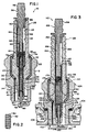
- the spark plug 10 ⁇ of the invention embodied in Fig. 1 has a conventional annular metallic shell 12 which has an annular external seat 14 below which is a length of reduced diameter which is externally threaded 16 for installing the spark plug into a threaded bore in the cylinder of an engine with seat 14 in sealing contact on an annular mounting boss on the cylinder head.
- Shell 12 is provided with a bore 18 therethrough with a first section 20 ⁇ having a shoulder 22 and a second section 24 of reduced diameter.
- a wrench-engageable head 26 is provided on the shell for threading the spark plug into the engine cylinder head.
- An elongated electrical insulator 28, which is preferably made of a sintered alumina ceramic is received in the bore of the shell 12.
- An annular shoulder 30 ⁇ on the insulator seats it on the shoulder 22 of the shell.
- An annular sleeve 32 of a relatively.soft metal having a high thermal conductivity is interposed between the insulator and the bore of the shell.
- Sleeve 32 surrounds the insulator in close thermal contact therewith and extends from an insulator upper shoulder 34 to shell shoulder 22 such that the lower end 36 of the sleeve acts to seal the insulator in the shell.
- Upper end 38 of the sleeve acts to protect the insulator when the upper rim 40 ⁇ of the shell is turned over to lock the insulator in the shell.
- Lower length 42 of the insulator is tapered to its firing end 44.
- the insulator has a centerbore 46 having a section 48 of a first diameter and a second section 50 ⁇ of a reduced diameter which tapers to a section 52 of a further reduced diameter receiving the center electrode 54.
- Center conductor assembly 56 comprises a terminal 58, a center conductor head 60 ⁇ , a heat pipe 62, and the center electrode 54.
- Terminal 58 is conventionally configured for connection with the ignition system of the engine in which the spark plug is installed.
- the terminal can be an integral part of the center conductor head which has a conductor shank 64 whose end portion 66 can be threaded for engagement with an interior threaded section 68 in the upper end of the heat pipe 62.
- the heat pipe is an elongated cylindrical chamber having a side wall 70 ⁇ and a lower end wall 72.
- a vaporizable heat pipe medium is placed in the heat pipe, normally in an amount slightly in excess to that required to wet completely the capillary means, and the heat pipe is hermetically sealed by installing an upper end wall or by threading end portion 66 of the center conductor shank into the heat pipe upper end. If a threaded closure is used, the interior volume of the heat pipe can be adjusted selectively by screwing the shank end portion inwardly or outwardly. As is known, an inert non-condensible gas can be introduced into the heat pipe to vary its thermal characteristics.
- the lower end of the heat pipe at the firing end of the spark plug forms the vaporization zone of the heat pipe and its upper end proximate the center conductor head forms the condensation zone with an adiabatic zone between the two.
- An annular metallic ring 76 having high thermal conductivity surrounds the heat pipe in intimate thermal contact therewith and the centerbore of the insulator proximate the condensation zone of the heat pipe.
- the center electrode 54 is positioned in the insulator centerbore section 52 with the firing tip 78 protruding from the firing end 44 of the insulator.
- a ground electrode 80 ⁇ welded on the lower rim of the shell is positioned with respect to the center electrode firing tip such that a spark gap 82 is formed therebetween.
- the center electrode and the lower end of the heat pipe and, if required, its upper end, are embedded in a suitable known fused conductive ceramic or glass seal 84 such that electrical and thermal continuity therebetween is assured.
- spark plug 10 ⁇ performs in a conventional manner to ignite the fuel/air mixture in the engine cylinder.
- the heat pipe is non-conducting such that the spark plug acts as a conventional "hot" plug with heat from the firing end being required to pass up the lower end of the insulator and, by means of the lower end 36 of the sleeve 32, travel through the shell and thence to the cylinder head of the engine to be dissipated into the cooling system thereof.
- the temperature gradient is very small over the entire length of a heat pipe and a large amount of heat is transferred.
- Heat from the condensation region of the heat pipe passes through ring 76. then through the insulator wall and by means of the annular sleeve 32 the heat passes to the shell shoulder and thence into the cylinder head of the engine for dissipation therein.
- heat is transferred rapidly from the firing end such that the temperatures of the spark plug remain relatively low to thereby avoid self-ignition, preignition, and thermal erosion problems. This may be considered to be the "cold" range of the spark plug. Should operating conditions cause engine cylinder temperatures to drop such that the firing end temperatures fall below the design range, the heat pipe will automatically cease to conduct heat. With the heat pipe becoming non-conducting, the spark plug will revert to its "hot" range.
- the heat pipe should be designed to become effective at about that temperature, preferably somewhere in the range between 450 ⁇ °C and 60 ⁇ 0 ⁇ °C. and the working medium and other design parameters should be chosen accordingly.
- a further embodiment of the invention is the spark plug 110 ⁇ shown in Fig. 3.
- Spark plug 110 ⁇ has an insulator 128 that differs from the Fig. 1 embodiment.
- the alumina or other ceramic used in the construction of insulator 128 is an excellent electrical insulator but its thermal conductivity is low.
- an annular section 186 in the waist of the insulator proximate the condensation zone of the heat pipe is reduced in diameter such that the thickness of the insulator wall in that region is reduced to a minimum consistent with the electrical insulation requirements of the insulator.
- the necked-in annular section 186 is filled in with a suitable material 190 ⁇ having the requisite strength properties and a high thermal conductivity.
- Figure 4 illustrates the upper portion of a spark plug 210 ⁇ of the invention showing means that can be provided to fill the dynamic convective heat transfer means which can be a heat pipe or a reflux condenser with the vaporizable medium and, if such is used. an inert non-condensible gas.
- the conductor shank 264 in this design is tubular with a centerbore 265 extending along its length and has a soft metal filling tube 267 received in the centerbore with its upper end 269 extending therefrom.
- the bore 271 of filling tube 267 can be of a size fitting a suitable heat pipe filling means (not shown).
- the heat pipe filling means injects a charge of the required heat pipe constituents into the filling tube where it passes through centerbore 265 and into the heat pipe. Following the charging of the heat pipe the end of the filling tube is pinched or crimped securely closed and may be soldered as is the usual practice.
- Centerbore 265 can be of a suitable size to serve as a partial reservoir for the inert, non-condensible gas, if such is used in the heat pipe.
- Figure 5 illustrates another embodiment 310 ⁇ of the spark plug of the invention. It differs in that the lower section 348 of insulator centerbore 346 forms the chamber of the heat pipe 362.
- the tubular conductor shank 364 of the center conductor assembly has a circular transverse end flange 369 which forms the upper end wall of the heat pipe 362.
- Centerbore 365 of the center conductor shank serves as the filling aperture of the heat pipe.
- a lower end wall (not shown) can be provided for the heat pipe should the requirements so dictate.
- the walls of the insulator centerbore lower section which form the heat pipe side walls are provided with electrically conducting capillary wicking means 374.
- spark plug 310 ⁇ of this embodiment operates identically with the previously described embodiments with the exception that condensation in the heat pipe takes place directly on the insulator centerbore wall such that the heat transfer characteristics of the device are improved.
- spark plug 410 ⁇ of the spark plug of the invention is illustrated in Fig. 6.
- the conductor shank 464 of the center conductor assembly extends through the heat pipe chamber and has a circular transverse end flange 471 which forms the lower end wall of the heat pipe and an upper circular transverse flange 469 which forms the upper end wall of the heat pipe.
- Centerbore 465 of the center conductor and a transverse passage 466 serve as the filling means for the heat pipe.
- the characteristics of spark plug 410 ⁇ are identical to the Fig. 5 embodiment except that non-electrically conducting wicking means 474 can be employed because the center conductor shank provides an electrical current path to the center electrode.
- FIG. 7 A further embodiment 510 ⁇ of the spark plug of the invention is shown in Fig. 7.
- capillary grooves 574 or other suitable wicking means are provided on the peripheral surface of the center conductor lower shank 564 and the under surface 567 of flange 569 which acts as the upper end wall of the heat pipe has a suitable thickness of wicking means 575.
- a reflux condenser type convective heat transfer means can be employed in applications where the sparking device is mounted vertically in an upright orientation such that gravity will return the condensate to the evaporation zone at the firing end whose operating temperature is being maintained.
- the working medium at the firing end vaporizes such that its change of state extracts heat therefrom. The vapor moves by vapor pressure to a region of lower temperature where it condenses on the wall bounding that region to release its heat by a change of state.
- the condensate flows back by gravity to the vaporization zone where the cycle is repeated as long as the design temperature is exceeded. It will be recognized that, inasmuch as gravity is depended upon to return the condensate to the vaporization zone, it is not required to provide capillary wicking to perform that function. Thus, as illustrated in Fig. 4, the walls of the insulator centerbore 246 need not be provided with capillary wicking means if the design employs a reflux condenser as the heat transfer means. The same condition applies if the bore of the center conductor rather than the insulator centerbore is utilized as the dynamic heat transfer means.
- a reflux condenser means of heat transfer is used in a design such as, for example, the embodiment 310 ⁇ of the spark plug of the invention shown in Fig. 5 wherein electrical continuity from the terminal to the center electrode is ensured by the use of an electrically conductive capillary wicking 374, the capillary wicking is not required and the wall of the insulator centerbore 346 will be furnished with a conductive coating of metal or the like to provide electrical continuity for the sparking current between the terminal and the center electrode.
Landscapes
- Spark Plugs (AREA)
- Ignition Installations For Internal Combustion Engines (AREA)
Claims (13)
- Zündkerze für Verbrennungskraftmaschinen mit einer dynamischen Wärmeübertragungseinrichtung (62) zur automatischen Veränderung ihres betrieblichen Wärmewerts entsprechend den Änderungen der Verbrennungstemperaturen in der Kraftmaschine, wobei die Zündkerze ein Anschlußende (58) und ein inneres Zündende (78) sowie ein ringförmiges metallisches Gehäuse (12) aufweist, welches eine Masseelektrode (80) trägt und mit einem Außengewinde (16) zum Einbau der Kerze in eine Kraftmaschine versehen und im Gehäuse (12) ein Isolator (28) eingesetzt ist, dessen am inneren Ende vorgesehener Fußabschnitt (42) konisch geformt und radial beabstandet zur Bohrung (18) des Gehäuses angeordnet ist, und in einer Mittelbohrung (46) im Isolator (28) eine mittige Leiteranordnung (56) vorgesehen ist, welche wenigstens das elektrische Anschlußende (58), einen mittigen Leiterschaft (64), besagte Wärmeübertragungseinrichtung (62), eine Einrichtung zur Befüllung der Warmeübertragungseinrichtung (62) und eine Mittelelektrode (54) umfaßt, deren Zündende (78) in bezug auf die Masseelektrode (80) so angeordnet ist, daß ein Zündspalt (82) zwischen ihnen gebildet ist, wobei die Wärmeübertragungseinrichtung (62) hermetisch dicht ausgebildet ist und ein verdampfbares Wärmeübertragungsmedium enthält und eine Verdampfungszone sowie eine Kondensationszone mit dazwischenliegender adiabatischer Zone aufweist, und unterhalb einer Auslegungstemperatur thermisch nicht leitend ist, so daß das Zündende (78) der Zündkerze sich so weit erhitzt, daß dort niedergeschlagene schädliche Abscheidungen verbrannt werden, während das Wärmeübertragungsmedium oberhalb der Auslegungstemperatur verdampft und infolge der Änderung seines Aggregatzustands Wärme vom Zündende (78) abführt, indem die besagten Dämpfe infolge des Dampfdrucks zur Kondensationszone strömen, dort kondensieren und die aufgenommene Wärme unter Änderung des Aggregatzustandes abgeben, worauf das kondensierte Medium zur Verdampfungszone zurückgeführt wird, so daß eine Zirkulation entsteht, welche Wärme vom Zündende (78) abführt, wenn die Zündkerzentemperatur die Auslegungstemperatur überschreitet und so eine Überhitzung vermieden wird, während die Zirkulation unterhalb der Auslegungstemperatur aufhört, um die Wärmeübertragungseinrichtung (42) thermisch nicht leitend werden zu lassen, wodurch die Wärmeübertragungseinrichtung (62) den betrieblichen Wärmebereich der Zündkerze automatisch steuert, und die Zündkerze ein in thermischer Verbindung mit der Kondensationszone wärmeleitendes Bauelement (76, 190) aufweist, welches innerhalb des Isolators (28) angeordnet ist.
- Zündkerze nach Anspruch 1, bei welcher die Wände der Isolator-Mittelbohrung (56) die Seitenwände (70) der Wärmeübertragungseinrichtung (62) bilden, Mittel zur Begrenzung der oberen und unteren Wände (72) der Wärmeübertragungseinrichtung (62) und Mittel zur Schaffung einer elektrischen Verbindung zwischen dem Anschlußende (58) und dem Zündende (78) der Zündkerze vorgesehen sind.
- Zündkerze nach Anspruch 1 oder 2, bei welcher die Wärmeübertragungseinrichtung von einem Wärmerohr (62) gebildet wird.
- Zündkerze nach Anspruch 1 oder 2, bei welcher die Wärmeübertragungseinrichtung von einem Rückflußkühler oder kondensator gebildet wird.
- Zündkerze nach Anspruch 1 oder 2, bei welcher der mittige leitende Schaft (264) eine in Flüssigkeitsverbindung mit den Wärmeübertragungsmitteln (62) stehende Axialbohrung (265) aufweist, und bei welcher die Axialbohrung (265) mit Fülleinrichtungen (267) zur Befüllung der Wärmeübertragungseinrichtung (62) versehen ist.
- Zündkerze nach Anspruch 1 oder 2, dadurch gekennzeichnet, daß die Zündkerze eine weitere Wärmeübertragungseinrichtung aufweist, welche eine den Isolator (28) in engem wärmeleitendem Kontakt umschließende rohrförmige Hülse (32) hoher thermischer Leitfähigkeit aufweist, wobei die Hülse (32) sich von der in der Nähe der Wärmerohr-Kondensations zone gelegenen Zone des Isolators (28) zu der in der Nähe des Bereichs (14) der Gehäusedichtung des Gehäuses (12) auf dem Zylinderkopf gelegenen Bohrung erstreckt, wodurch eine hoch wärmeleitende Verbindung vom Wärmerohr zu einer zur Wärmeableitung dienenden Wärmesenke gebildet wird.
- Zündkerze nach Anspruch 1 oder 2, bei welcher der elektrische Isolator aus einem Material mit relativ geringer thermischer Leitfähigkeit hergestellt ist und einen ringförmigen eingezogenen Bereich (186) in der Nähe der Kondensationszone der Wärmeübertragungseinrichtung aufweist, um die Dicke des relativ schlecht wärmeleitenden Materials im Wärmeabfuhr-Weg von den Wärmeübertragungseinrichtungen zu verringern, wobei der eingezogene Bereich (186) mit relativ gut wärmeleitendem Material (190) ausgefüllt ist.
- Zündkerze nach Anspruch 1 oder 2, bei welcher Einrichtungen zur wahlweisen Veränderung des Volumens der Wärmeübertragungseinrichtungen derart vorgesehen sind, daß ihre thermischen Eigenschaften veränderbar sind.
- Zündkerze nach Anspruch 8, bei welcher der langgestreckte Mittelleiter (56) ein unteres Wärmeübertragungseinrichtungs-Ende (66) und ein oberes Anschlußende (64) aufweist, und bei dem die Einrichtungen zur selektiven Veränderung des Volumens der Wärmeübertragungseinrichtung (62) von einem Gewindeabschnitt (68) in der Bohrung des oberen Kondensatorendes der Wärmeübertragungseinrichtung (32) und einem Gewindeabschnitt (66) im unteren Ende der Wärmeübertragungseinrichtung gebildet werden, wobei besagtes unteres Ende (66) so in das obere Ende des Kondensatorabschnitts eingeschraubt ist, daß das Anschlußende (64) zur Veränderung des Volumens besagter Wärmeübertragungseinrichtung ein- oder herausschraubbar ist.
- Zündkerze nach Anspruch 3, bei welcher das Wärmerohr Kapillar-Einrichtungen (74) aufweist, welche sich von seiner Kondensationszone zu seiner Verdampfungszone erstrekken, und bei welchem die oberen und unteren Wände und die Kapillar-Einrichtungen (74) elektrisch leitend sind und die Kapillar-Einrichtungen auf den Wänden (70) des Wärmerohrs (62) vorgesehen sind.
- Zündkerze nach Anspruch 3, bei welcher das Wärmerohr Kapillar-Einrichtungen (74) aufweist, welche sich von seiner Kondensationszone zu seiner Verdampfungszone erstrecken und bei welchem der mittige Leiterschaft (464) sich durch das Wärmerohr (62) erstreckt und eine elektrische Verbindung zwischen dem Anschlußende (58) und dem Zündende (78) bildet, und die Kapillar-Einrichtungen auf den Wänden des Wärmerohrs vorgesehen sind.
- Zündkerze nach Anspruch 3, bei welcher das Wärmerohr (62) Kapillar-Einrichtungen (74) aufweist, welche sich von seiner Kondensationszone in seine Verdampfungszone erstrekken, wobei der mittige Leiterschaft (564) sich durch das Wärmerohr (62) erstreckt und so eine elektrische Verbindung zwischen dem Anschlußende (58) und dem Zündende (78) bildet, wobei die Kapillar-Einrichtungen (574) auf dem mittigen Leiterschaft (564) und wenigstens auf der Innenfläche (567) der oberen Wand (569) des Wärmerohrs (62) vorgesehen sind.
- Zündkerze nach Anspruch 1 oder 2, bei welcher die Wärmeleiteinrichtung (76) einen hülsenförmigen Metallring (76) hoher thermischer Leitfähigkeit aufweist, welcher die Wärmeübertragungseinrichtung (62) umgibt.
Applications Claiming Priority (3)
| Application Number | Priority Date | Filing Date | Title |
|---|---|---|---|
| US219826 | 1988-07-15 | ||
| US07/219,826 US4810929A (en) | 1987-03-30 | 1988-07-15 | Spark plug temperature control |
| PCT/US1989/000503 WO1990000821A1 (en) | 1988-07-15 | 1989-02-08 | Spark plug temperature control |
Publications (3)
| Publication Number | Publication Date |
|---|---|
| EP0378591A1 EP0378591A1 (de) | 1990-07-25 |
| EP0378591A4 EP0378591A4 (en) | 1990-12-05 |
| EP0378591B1 true EP0378591B1 (de) | 1995-01-18 |
Family
ID=22820939
Family Applications (1)
| Application Number | Title | Priority Date | Filing Date |
|---|---|---|---|
| EP89903410A Expired - Lifetime EP0378591B1 (de) | 1988-07-15 | 1989-02-08 | Temperaturregelung von zündkerzen |
Country Status (6)
| Country | Link |
|---|---|
| US (1) | US4810929A (de) |
| EP (1) | EP0378591B1 (de) |
| JP (1) | JPH03501308A (de) |
| KR (1) | KR970008577B1 (de) |
| DE (1) | DE68920725T2 (de) |
| WO (1) | WO1990000821A1 (de) |
Families Citing this family (52)
| Publication number | Priority date | Publication date | Assignee | Title |
|---|---|---|---|---|
| US4972812A (en) * | 1989-08-30 | 1990-11-27 | Strumbos William P | Spark plug thermal control |
| US5091672A (en) * | 1990-06-26 | 1992-02-25 | Allied-Signal Inc. | Shield for aligning a ground electrode of a spark plug in a cylinder head |
| WO1993006246A1 (en) * | 1991-09-19 | 1993-04-01 | Amoco Corporation | Production of chromosome region specific dna sequences and transamination |
| US6152095A (en) * | 1996-11-14 | 2000-11-28 | Quik-Change Int'l., L.L.C. | Quick replacement spark plug assembly |
| US6167948B1 (en) | 1996-11-18 | 2001-01-02 | Novel Concepts, Inc. | Thin, planar heat spreader |
| US6194819B1 (en) | 1997-12-09 | 2001-02-27 | Caterpillar Inc. | Spark plug with lower operating temperature |
| DE10047498A1 (de) * | 2000-09-26 | 2002-04-18 | Bosch Gmbh Robert | Zündkerze kompakter Bauart und Herstellungsverfahren |
| FR2886776B1 (fr) * | 2005-06-07 | 2012-08-17 | Renault Sas | Electrode notamment d'une bougie d'allumage de moteur a combustion interne |
| US7357101B2 (en) * | 2005-11-30 | 2008-04-15 | Ford Global Technologies, Llc | Engine system for multi-fluid operation |
| US7730872B2 (en) | 2005-11-30 | 2010-06-08 | Ford Global Technologies, Llc | Engine with water and/or ethanol direct injection plus gas port fuel injectors |
| US7640912B2 (en) * | 2005-11-30 | 2010-01-05 | Ford Global Technologies, Llc | System and method for engine air-fuel ratio control |
| US7412966B2 (en) | 2005-11-30 | 2008-08-19 | Ford Global Technologies, Llc | Engine output control system and method |
| US7395786B2 (en) * | 2005-11-30 | 2008-07-08 | Ford Global Technologies, Llc | Warm up strategy for ethanol direct injection plus gasoline port fuel injection |
| US7594498B2 (en) * | 2005-11-30 | 2009-09-29 | Ford Global Technologies, Llc | System and method for compensation of fuel injector limits |
| US7647916B2 (en) * | 2005-11-30 | 2010-01-19 | Ford Global Technologies, Llc | Engine with two port fuel injectors |
| US7302933B2 (en) * | 2005-11-30 | 2007-12-04 | Ford Global Technologies Llc | System and method for engine with fuel vapor purging |
| US7406947B2 (en) | 2005-11-30 | 2008-08-05 | Ford Global Technologies, Llc | System and method for tip-in knock compensation |
| US8132555B2 (en) * | 2005-11-30 | 2012-03-13 | Ford Global Technologies, Llc | Event based engine control system and method |
| US8434431B2 (en) * | 2005-11-30 | 2013-05-07 | Ford Global Technologies, Llc | Control for alcohol/water/gasoline injection |
| US7877189B2 (en) * | 2005-11-30 | 2011-01-25 | Ford Global Technologies, Llc | Fuel mass control for ethanol direct injection plus gasoline port fuel injection |
| US7293552B2 (en) | 2005-11-30 | 2007-11-13 | Ford Global Technologies Llc | Purge system for ethanol direct injection plus gas port fuel injection |
| US7647899B2 (en) * | 2006-03-17 | 2010-01-19 | Ford Global Technologies, Llc | Apparatus with mixed fuel separator and method of separating a mixed fuel |
| US8267074B2 (en) * | 2006-03-17 | 2012-09-18 | Ford Global Technologies, Llc | Control for knock suppression fluid separator in a motor vehicle |
| US7779813B2 (en) * | 2006-03-17 | 2010-08-24 | Ford Global Technologies, Llc | Combustion control system for an engine utilizing a first fuel and a second fuel |
| US7665452B2 (en) * | 2006-03-17 | 2010-02-23 | Ford Global Technologies, Llc | First and second spark plugs for improved combustion control |
| US7665428B2 (en) | 2006-03-17 | 2010-02-23 | Ford Global Technologies, Llc | Apparatus with mixed fuel separator and method of separating a mixed fuel |
| US7533651B2 (en) | 2006-03-17 | 2009-05-19 | Ford Global Technologies, Llc | System and method for reducing knock and preignition in an internal combustion engine |
| US7255080B1 (en) | 2006-03-17 | 2007-08-14 | Ford Global Technologies, Llc | Spark plug heating for a spark ignited engine |
| US7578281B2 (en) * | 2006-03-17 | 2009-08-25 | Ford Global Technologies, Llc | First and second spark plugs for improved combustion control |
| US7581528B2 (en) | 2006-03-17 | 2009-09-01 | Ford Global Technologies, Llc | Control strategy for engine employng multiple injection types |
| US7389751B2 (en) * | 2006-03-17 | 2008-06-24 | Ford Global Technology, Llc | Control for knock suppression fluid separator in a motor vehicle |
| US7933713B2 (en) * | 2006-03-17 | 2011-04-26 | Ford Global Technologies, Llc | Control of peak engine output in an engine with a knock suppression fluid |
| US7740009B2 (en) * | 2006-03-17 | 2010-06-22 | Ford Global Technologies, Llc | Spark control for improved engine operation |
| US8015951B2 (en) * | 2006-03-17 | 2011-09-13 | Ford Global Technologies, Llc | Apparatus with mixed fuel separator and method of separating a mixed fuel |
| US7681554B2 (en) * | 2006-07-24 | 2010-03-23 | Ford Global Technologies, Llc | Approach for reducing injector fouling and thermal degradation for a multi-injector engine system |
| US7909019B2 (en) | 2006-08-11 | 2011-03-22 | Ford Global Technologies, Llc | Direct injection alcohol engine with boost and spark control |
| US7287509B1 (en) | 2006-08-11 | 2007-10-30 | Ford Global Technologies Llc | Direct injection alcohol engine with variable injection timing |
| US7461628B2 (en) | 2006-12-01 | 2008-12-09 | Ford Global Technologies, Llc | Multiple combustion mode engine using direct alcohol injection |
| US7676321B2 (en) * | 2007-08-10 | 2010-03-09 | Ford Global Technologies, Llc | Hybrid vehicle propulsion system utilizing knock suppression |
| US8214130B2 (en) * | 2007-08-10 | 2012-07-03 | Ford Global Technologies, Llc | Hybrid vehicle propulsion system utilizing knock suppression |
| US7971567B2 (en) | 2007-10-12 | 2011-07-05 | Ford Global Technologies, Llc | Directly injected internal combustion engine system |
| US8118009B2 (en) | 2007-12-12 | 2012-02-21 | Ford Global Technologies, Llc | On-board fuel vapor separation for multi-fuel vehicle |
| US8550058B2 (en) | 2007-12-21 | 2013-10-08 | Ford Global Technologies, Llc | Fuel rail assembly including fuel separation membrane |
| US8141356B2 (en) * | 2008-01-16 | 2012-03-27 | Ford Global Technologies, Llc | Ethanol separation using air from turbo compressor |
| US7845315B2 (en) | 2008-05-08 | 2010-12-07 | Ford Global Technologies, Llc | On-board water addition for fuel separation system |
| EP2383847B1 (de) * | 2008-12-25 | 2019-09-18 | Ngk Spark Plug Co., Ltd. | Zündkerze |
| DE102009047055A1 (de) * | 2009-11-24 | 2011-05-26 | Robert Bosch Gmbh | Zündkerze für eine Verbrennungskraftmaschine |
| EP2581998B1 (de) * | 2011-10-14 | 2019-12-18 | Delphi Automotive Systems Luxembourg SA | Zündkerze für Hochfrequenz-Zündsystem |
| FR2995461B1 (fr) * | 2012-09-12 | 2014-08-22 | Renault Sa | "bougie d'allumage de type a etincelle radiofrequence a refroidissement integre" |
| US20160003150A1 (en) * | 2014-07-03 | 2016-01-07 | General Electric Company | Igniter tip with cooling passage |
| JP7125289B2 (ja) * | 2018-06-29 | 2022-08-24 | 株式会社Soken | 内燃機関用の点火装置 |
| GB2608652B (en) * | 2021-07-09 | 2023-08-30 | Caterpillar Energy Solutions Gmbh | Spark plug |
Family Cites Families (10)
| Publication number | Priority date | Publication date | Assignee | Title |
|---|---|---|---|---|
| US1315298A (en) * | 1919-09-09 | John e | ||
| US2096250A (en) * | 1933-09-08 | 1937-10-19 | Armen A Kasarjian | Spark plug |
| JPS5259234A (en) * | 1975-11-11 | 1977-05-16 | Toyota Motor Corp | Ignition plug |
| DE2831452A1 (de) * | 1978-07-18 | 1980-01-31 | Bosch Gmbh Robert | Brennkraftmaschine mit einem hauptbrennraum und einer in eine zuendkammer eingesetzten zuendeinrichtung |
| DE2951029A1 (de) * | 1979-12-19 | 1981-06-25 | Robert Bosch Gmbh, 7000 Stuttgart | Fremdgezuendete brennkraftmaschine mit je einem hauptbrennraum pro zylinder und einer zuendkammer |
| JPS56106387A (en) * | 1980-01-25 | 1981-08-24 | Nippon Denso Co | Ignition plug |
| DE3017948A1 (de) * | 1980-05-10 | 1981-11-19 | Robert Bosch Gmbh, 7000 Stuttgart | Fremdgezuendete brennkraftmaschine mit einer jeweils dem hauptbrennraum zugeordneten zuendkammer |
| DE3148296A1 (de) * | 1981-01-17 | 1982-09-02 | Robert Bosch Gmbh, 7000 Stuttgart | Fremdgezuendete brennkraftmaschine mit wenigstens einem hauptbrennraum und einer diesem zugeordneten zuendkammer |
| DE3147291A1 (de) * | 1981-11-28 | 1983-06-01 | Robert Bosch Gmbh, 7000 Stuttgart | Sensor |
| US4491101A (en) * | 1983-09-06 | 1985-01-01 | Strumbos William P | Multiple heat-range spark plug |
-
1988
- 1988-07-15 US US07/219,826 patent/US4810929A/en not_active Expired - Fee Related
-
1989
- 1989-02-08 WO PCT/US1989/000503 patent/WO1990000821A1/en not_active Ceased
- 1989-02-08 EP EP89903410A patent/EP0378591B1/de not_active Expired - Lifetime
- 1989-02-08 KR KR1019900700557A patent/KR970008577B1/ko not_active Expired - Lifetime
- 1989-02-08 JP JP1503062A patent/JPH03501308A/ja active Pending
- 1989-02-08 DE DE68920725T patent/DE68920725T2/de not_active Expired - Fee Related
Also Published As
| Publication number | Publication date |
|---|---|
| WO1990000821A1 (en) | 1990-01-25 |
| US4810929A (en) | 1989-03-07 |
| JPH03501308A (ja) | 1991-03-22 |
| EP0378591A4 (en) | 1990-12-05 |
| KR970008577B1 (ko) | 1997-05-27 |
| KR900702609A (ko) | 1990-12-07 |
| DE68920725D1 (de) | 1995-03-02 |
| DE68920725T2 (de) | 1995-06-29 |
| EP0378591A1 (de) | 1990-07-25 |
Similar Documents
| Publication | Publication Date | Title |
|---|---|---|
| EP0378591B1 (de) | Temperaturregelung von zündkerzen | |
| US11581708B2 (en) | Spark plug with thermally coupled center electrode | |
| US8294346B2 (en) | Open-chamber multi-spark plug | |
| US4963784A (en) | Spark plug having combined surface and air gaps | |
| US4491101A (en) | Multiple heat-range spark plug | |
| US7714488B2 (en) | Plasma jet spark plug and ignition system for the same | |
| JPS621092B2 (de) | ||
| US4539503A (en) | Rapid-heating, high-temperature-stable spark plug for internal combustion engines | |
| US4972812A (en) | Spark plug thermal control | |
| JP2003187944A (ja) | 電流ピーキング点火プラグ | |
| US11552456B1 (en) | Pre-chamber spark plug | |
| HUT76207A (en) | Spark plug | |
| US3612931A (en) | Multiple heat range spark plug | |
| US4007391A (en) | Igniters | |
| JP4970458B2 (ja) | 自動車の内燃機関用スパークプラグ | |
| US2096250A (en) | Spark plug | |
| JP6645168B2 (ja) | 点火プラグ | |
| US5705892A (en) | Spark ignition system and spark plug for ultra lean fuel/air mixtures | |
| US3431450A (en) | Spark plug with adjustable electrode gap | |
| CN114746633A (zh) | 具有预燃室点火系统的火花点火的往复活塞式内燃机 | |
| US2318440A (en) | Spark plug | |
| US1314129A (en) | crowther | |
| RU2007004C1 (ru) | Полупроводниковая свеча зажигания | |
| JPH0494076A (ja) | 放電管内蔵型点火プラグ装置 | |
| CN223093306U (zh) | 火花塞、发动机及车辆 |
Legal Events
| Date | Code | Title | Description |
|---|---|---|---|
| PUAI | Public reference made under article 153(3) epc to a published international application that has entered the european phase |
Free format text: ORIGINAL CODE: 0009012 |
|
| AK | Designated contracting states |
Kind code of ref document: A1 Designated state(s): DE GB |
|
| 17P | Request for examination filed |
Effective date: 19900915 |
|
| A4 | Supplementary search report drawn up and despatched |
Effective date: 19901018 |
|
| AK | Designated contracting states |
Kind code of ref document: A4 Designated state(s): DE GB |
|
| 17Q | First examination report despatched |
Effective date: 19921217 |
|
| GRAA | (expected) grant |
Free format text: ORIGINAL CODE: 0009210 |
|
| RAP1 | Party data changed (applicant data changed or rights of an application transferred) |
Owner name: STRUMBOS, GEORGE Owner name: STRUMBOS, CAROL, D. |
|
| AK | Designated contracting states |
Kind code of ref document: B1 Designated state(s): DE GB |
|
| REF | Corresponds to: |
Ref document number: 68920725 Country of ref document: DE Date of ref document: 19950302 |
|
| PLBE | No opposition filed within time limit |
Free format text: ORIGINAL CODE: 0009261 |
|
| STAA | Information on the status of an ep patent application or granted ep patent |
Free format text: STATUS: NO OPPOSITION FILED WITHIN TIME LIMIT |
|
| 26N | No opposition filed | ||
| PGFP | Annual fee paid to national office [announced via postgrant information from national office to epo] |
Ref country code: GB Payment date: 19970121 Year of fee payment: 9 |
|
| PGFP | Annual fee paid to national office [announced via postgrant information from national office to epo] |
Ref country code: DE Payment date: 19970411 Year of fee payment: 9 |
|
| PG25 | Lapsed in a contracting state [announced via postgrant information from national office to epo] |
Ref country code: GB Free format text: LAPSE BECAUSE OF NON-PAYMENT OF DUE FEES Effective date: 19980208 |
|
| GBPC | Gb: european patent ceased through non-payment of renewal fee |
Effective date: 19980208 |
|
| PG25 | Lapsed in a contracting state [announced via postgrant information from national office to epo] |
Ref country code: DE Free format text: LAPSE BECAUSE OF NON-PAYMENT OF DUE FEES Effective date: 19981103 |