EP0376442B1 - Gas turbine igniter with balljoint support - Google Patents
Gas turbine igniter with balljoint support Download PDFInfo
- Publication number
- EP0376442B1 EP0376442B1 EP89310248A EP89310248A EP0376442B1 EP 0376442 B1 EP0376442 B1 EP 0376442B1 EP 89310248 A EP89310248 A EP 89310248A EP 89310248 A EP89310248 A EP 89310248A EP 0376442 B1 EP0376442 B1 EP 0376442B1
- Authority
- EP
- European Patent Office
- Prior art keywords
- igniter
- hole
- ball joint
- combustor
- liner
- Prior art date
- Legal status (The legal status is an assumption and is not a legal conclusion. Google has not performed a legal analysis and makes no representation as to the accuracy of the status listed.)
- Expired - Lifetime
Links
Images
Classifications
-
- F—MECHANICAL ENGINEERING; LIGHTING; HEATING; WEAPONS; BLASTING
- F02—COMBUSTION ENGINES; HOT-GAS OR COMBUSTION-PRODUCT ENGINE PLANTS
- F02C—GAS-TURBINE PLANTS; AIR INTAKES FOR JET-PROPULSION PLANTS; CONTROLLING FUEL SUPPLY IN AIR-BREATHING JET-PROPULSION PLANTS
- F02C7/00—Features, components parts, details or accessories, not provided for in, or of interest apart form groups F02C1/00 - F02C6/00; Air intakes for jet-propulsion plants
- F02C7/26—Starting; Ignition
- F02C7/264—Ignition
- F02C7/266—Electric
-
- F—MECHANICAL ENGINEERING; LIGHTING; HEATING; WEAPONS; BLASTING
- F23—COMBUSTION APPARATUS; COMBUSTION PROCESSES
- F23R—GENERATING COMBUSTION PRODUCTS OF HIGH PRESSURE OR HIGH VELOCITY, e.g. GAS-TURBINE COMBUSTION CHAMBERS
- F23R3/00—Continuous combustion chambers using liquid or gaseous fuel
- F23R3/28—Continuous combustion chambers using liquid or gaseous fuel characterised by the fuel supply
- F23R3/283—Attaching or cooling of fuel injecting means including supports for fuel injectors, stems, or lances
Definitions
- the present invention relates to combustors for gas turbines and, more particularly, to igniters for igniting a fuel-air mixture in a combustor of a gas turbine engine.
- An igniter for the combustor of a gas turbine engine permits the production of an electrical spark across a gap formed between oppositely charged electrodes. The spark so produced is effective for igniting a combustible fuel-air mixture within the combustor.
- U.S. Patent No. 4,275,559 discloses an igniter which is affixed to a combustion chamber with the electrodes extending a short distance to an ignition position in the combustor.
- This device includes spring retention of the electrodes in the ignition position. The spring permits the electrodes to retract from the combustor in the presence of high pressure within the combustor, as occurs once ignition is attained.
- Non-retracting igniters are known wherein the igniter is affixed to a combustor casing and the electrodes extend inward through an opening a short distance to a fixed ignition position within the combustor liner.
- One way of decreasing leakage includes a sliding seal sealing between the igniter and an over-sized hole in the combustor liner.
- sliding seals represent a substantial cost, and are thus avoided if possible.
- Another way of avoiding leakage includes making the hole through the combustor liner a close fit to the igniter electrode.
- US-A-3487636 discloses a spark igniter for an after burner of a gas turbine engine.
- the after burner duct comprises a casing having a liner.
- Flame holders are disposed within the after burner duct.
- An igniter extends between the casing and one of the flame holders.
- a body section of the igniter is supported at one end within a ball joint on the casing and is slidably supported at the other end within a portion of the flame holder.
- the portion of the igniter within the flame holder includes an igniter tip.
- a combustor for a gas turbine said combustor including a casing; a liner within said casing; an igniter; a ball joint; a body section of said igniter being affixed in said ball joint; an igniter tip on said body section; a hole in said liner; said igniter tip entering through said hole and into an interior of said liner; said hole being a tight fit to said igniter tip, whereby leakage past said igniter tip through said hole is limited; and means supporting said ball joint spaced a substantial distance outward from said casing; said ball joint, and said body section being rotatable through sufficient range to permit fitting said igniter tip in said hole in the presence of manufacturing tolerances, and to permit said igniter tip to track said hole in the presence of differential thermal expansion during operation.
- An embodiment of the combustor further comprises at least one seal contacting a surface of said ball joint, said at least one seal being of a material effective to perform a sealing function and to resist high temperature.
- said at least one seal is a carbon foil.
- said means for supporting said ball joint comprises a standoff cylinder and said ball joint is supported at a distal end of said standoff cylinder.
- the following description is directed to an igniter for a gas turbine engine wherein the position of the electrodes is fixed. That is, the tips of the electrodes remain in an ignition position, just within a combustor liner, at all times. This should not be taken to preclude application of the present invention to a retractable igniter such as disclosed, for example, in the referenced '559 patent.
- FIG. 1 there is shown, generally at 10, relevant portions of a gas turbine combustor.
- a combustor liner 12 is disposed within a combustor casing 14.
- a flow sleeve 16 is mounted within combustor casing 14 and spaced a substantial distance outward from combustor liner 12.
- the space between flow sleeve 16 and combustor liner 12 forms a portion of a plenum 18 receiving a flow of pressurized air 20 from a compressor (not shown).
- combustor liner 12 includes a plurality of slots 22 for permitting pressurized air to flow through combustor liner 12 to provide combustion, cooling and dilution air within an interior 24 of combustor liner 12.
- a conventional fuel nozzle (not shown) injects liquid or gaseous fuel into interior 24 where it is burned with the air entering through slots 22.
- a hot energetic exhaust flow of products of combustion, excess fuel and/or excess air move in a direction indicated by an arrow 26 toward turbine blades (not shown) to produce the desired work.
- a mounting base 28 is affixed rigidly to combustor casing 14 by, for example, a peripheral weld.
- An igniter shown generally at 30, includes a mounting flange 32 adapted for attachment to mounting base 28 using, for example, a plurality of bolts 34.
- a seal 36 between facing surfaces of mounting base 28 and 32, prevents air leakage therepast.
- a standoff cylinder 38 is affixed, at its lower end, in a hole 40 in mounting flange 32.
- An inner flange 42 is affixed to the outer end of standoff cylinder 38.
- An intermediate flange 44 is affixed to inner flange 42 using, for example, one or more bolts 46.
- a seal 48 between facing surfaces of inner flange 42 and intermediate flange 44 prevents air leakage therepast.
- Intermediate flange 44 includes a depression 50 for accommodating the lower hemisphere of a ball 52.
- An outer flange 54 is affixed atop intermediate flange 44 using, for example, one or more bolts 56.
- a seal 58 between facing surfaces of intermediate flange 44 and 54 prevents air leakage therepast.
- Outer flange 54 includes a depression 60 for accommodating the upper hemisphere of ball 52.
- An inner seal 62 in depression 50 makes rubbing and sealing contact with the lower hemisphere of ball 52.
- An outer seal 64 in outer flange 54 makes rubbing and sealing contact with the upper hemisphere of ball 52.
- Inner seal 62 and outer seal 64 can be of any convenient material, however, carbon foil is preferred among presently available materials for its self-lubricating and heat-resisting properties.
- a body section 66 is affixed in ball 52. It will be noted that a substantial clearance volume 68 is provided between an exterior surface of body section 66 and an interior surface of standoff cylinder 38. This permits body section 66 to rotate on ball 52 over a substantial distance within standoff cylinder 38.
- An electrode section 70 extends inward beyond an inner extremity of body section 66 toward combustor liner 12.
- An electrode tip 72 extends beyond electrode section 70, and through a tight-fitting hole 74 to position electrode tip 72 in an ignition position.
- An electrical connector 76 at a distal end of body section 66, permits connection of a source of electricity (not shown) for producing a spark across electrode tip 72.
- body section 66 is rotated on ball 52 as necessary to fit electrode tip 72 through hole 74 in combustor liner 12. This provides accommodation for a substantial amount of positioning errors inevitably resulting from manufacturing tolerances.
- body section 66 is rotated on ball 52 as necessary to fit electrode tip 72 through hole 74 in combustor liner 12.
Landscapes
- Engineering & Computer Science (AREA)
- Chemical & Material Sciences (AREA)
- Combustion & Propulsion (AREA)
- Mechanical Engineering (AREA)
- General Engineering & Computer Science (AREA)
- Turbine Rotor Nozzle Sealing (AREA)
Description
- The present invention relates to combustors for gas turbines and, more particularly, to igniters for igniting a fuel-air mixture in a combustor of a gas turbine engine.
- An igniter for the combustor of a gas turbine engine permits the production of an electrical spark across a gap formed between oppositely charged electrodes. The spark so produced is effective for igniting a combustible fuel-air mixture within the combustor.
- U.S. Patent No. 4,275,559 discloses an igniter which is affixed to a combustion chamber with the electrodes extending a short distance to an ignition position in the combustor. This device includes spring retention of the electrodes in the ignition position. The spring permits the electrodes to retract from the combustor in the presence of high pressure within the combustor, as occurs once ignition is attained.
- Non-retracting igniters are known wherein the igniter is affixed to a combustor casing and the electrodes extend inward through an opening a short distance to a fixed ignition position within the combustor liner.
- It is desirable to avoid leakage of a large flow of air between the igniter electrode and the opening in the combustor liner. This desirable object is complicated by large differential thermal expansion of the casing and the liner, and by the stackup of manufacturing tolerances. This combination can have a cumulative effect of as much as 6.35mm (0.25 inch).
- One way of decreasing leakage includes a sliding seal sealing between the igniter and an over-sized hole in the combustor liner. Experience has shown that sliding seals represent a substantial cost, and are thus avoided if possible.
- Another way of avoiding leakage includes making the hole through the combustor liner a close fit to the igniter electrode. With the build-up of position errors due to the sum of manufacturing tolerances and differential thermal expansion, a rigidly mounted device of the referenced '559 patent, if fitted through a close-fitting hole in a combustor liner of a large gas turbine engine, would exert unacceptable forces on the combustor liner.
- Other U.S. Patents showing igniters for combustors of gas turbine engines are 4,125,998 and 4,597,260.
- US-A-3487636 discloses a spark igniter for an after burner of a gas turbine engine. The after burner duct comprises a casing having a liner. Flame holders are disposed within the after burner duct. An igniter extends between the casing and one of the flame holders. A body section of the igniter is supported at one end within a ball joint on the casing and is slidably supported at the other end within a portion of the flame holder. The portion of the igniter within the flame holder includes an igniter tip.
- According to the invention, there is provided a combustor for a gas turbine, said combustor including a casing; a liner within said casing; an igniter; a ball joint; a body section of said igniter being affixed in said ball joint; an igniter tip on said body section; a hole in said liner; said igniter tip entering through said hole and into an interior of said liner; said hole being a tight fit to said igniter tip, whereby leakage past said igniter tip through said hole is limited; and means supporting said ball joint spaced a substantial distance outward from said casing; said ball joint, and said body section being rotatable through sufficient range to permit fitting said igniter tip in said hole in the presence of manufacturing tolerances, and to permit said igniter tip to track said hole in the presence of differential thermal expansion during operation.
- An embodiment of the combustor further comprises at least one seal contacting a surface of said ball joint, said at least one seal being of a material effective to perform a sealing function and to resist high temperature. Preferably said at least one seal is a carbon foil.
- In a preferred embodiment said means for supporting said ball joint comprises a standoff cylinder and said ball joint is supported at a distal end of said standoff cylinder.
- A better understanding of the present invention will become apparent from the following description read in conjunction with the accompanying drawing , in which
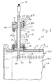
- Fig. 1 is partial cross section of a combustor of a gas turbine engine showing an igniter mounting system according to an embodiment of the invention.
- The following description is directed to an igniter for a gas turbine engine wherein the position of the electrodes is fixed. That is, the tips of the electrodes remain in an ignition position, just within a combustor liner, at all times. This should not be taken to preclude application of the present invention to a retractable igniter such as disclosed, for example, in the referenced '559 patent.
- Referring to Fig. 1, there is shown, generally at 10, relevant portions of a gas turbine combustor. A
combustor liner 12 is disposed within acombustor casing 14. Aflow sleeve 16 is mounted withincombustor casing 14 and spaced a substantial distance outward fromcombustor liner 12. The space betweenflow sleeve 16 andcombustor liner 12 forms a portion of aplenum 18 receiving a flow of pressurizedair 20 from a compressor (not shown). As is conventional,combustor liner 12 includes a plurality of slots 22 for permitting pressurized air to flow throughcombustor liner 12 to provide combustion, cooling and dilution air within an interior 24 ofcombustor liner 12. A conventional fuel nozzle (not shown) injects liquid or gaseous fuel into interior 24 where it is burned with the air entering through slots 22. A hot energetic exhaust flow of products of combustion, excess fuel and/or excess air move in a direction indicated by anarrow 26 toward turbine blades (not shown) to produce the desired work. - A
mounting base 28 is affixed rigidly tocombustor casing 14 by, for example, a peripheral weld. An igniter, shown generally at 30, includes amounting flange 32 adapted for attachment to mountingbase 28 using, for example, a plurality of bolts 34. Aseal 36, between facing surfaces ofmounting base standoff cylinder 38 is affixed, at its lower end, in a hole 40 inmounting flange 32. Aninner flange 42 is affixed to the outer end ofstandoff cylinder 38. Anintermediate flange 44 is affixed toinner flange 42 using, for example, one ormore bolts 46. A seal 48 between facing surfaces ofinner flange 42 andintermediate flange 44 prevents air leakage therepast.Intermediate flange 44 includes adepression 50 for accommodating the lower hemisphere of a ball 52. Anouter flange 54 is affixed atopintermediate flange 44 using, for example, one ormore bolts 56. A seal 58 between facing surfaces ofintermediate flange Outer flange 54 includes adepression 60 for accommodating the upper hemisphere of ball 52. Aninner seal 62 indepression 50 makes rubbing and sealing contact with the lower hemisphere of ball 52. An outer seal 64 inouter flange 54 makes rubbing and sealing contact with the upper hemisphere of ball 52. -
Inner seal 62 and outer seal 64 can be of any convenient material, however, carbon foil is preferred among presently available materials for its self-lubricating and heat-resisting properties. - A
body section 66 is affixed in ball 52. It will be noted that asubstantial clearance volume 68 is provided between an exterior surface ofbody section 66 and an interior surface ofstandoff cylinder 38. This permitsbody section 66 to rotate on ball 52 over a substantial distance withinstandoff cylinder 38. Anelectrode section 70 extends inward beyond an inner extremity ofbody section 66 towardcombustor liner 12. Anelectrode tip 72 extends beyondelectrode section 70, and through a tight-fitting hole 74 to positionelectrode tip 72 in an ignition position. - An
electrical connector 76, at a distal end ofbody section 66, permits connection of a source of electricity (not shown) for producing a spark acrosselectrode tip 72. - During installation of igniter 30 in
gas turbine combustor 10,body section 66 is rotated on ball 52 as necessary to fitelectrode tip 72 throughhole 74 incombustor liner 12. This provides accommodation for a substantial amount of positioning errors inevitably resulting from manufacturing tolerances. During use, if differential thermal expansion causes a change in the relative positions ofmounting base 28 andhole 74, a force is applied toelectrode tip 72 byhole 74, resulting in the rotation ofbody section 66 about ball 52 as necessary to limit stresses applied tobody section 66, even whenhole 74 is tightly fitted aboutelectrode tip 72.
Claims (4)
- A combustor (10) for a gas turbine, said combustor including :
a casing (14);
a liner (12) within said casing (14);
an igniter (30);
a ball joint (52);
a body section (66) of said igniter (30) being affixed in said ball joint (52);
an igniter tip (72) on said body section (66);
characterized by:
a hole (74) in said liner (12);
said igniter tip (72) entering through said hole (74) and into an interior (24) of said liner (12);
said hole (74) being a tight fit to said igniter tip (72), whereby leakage past said igniter tip (72) through said hole (74) is limited; and
means (38) supporting said ball joint (52) spaced a substantial distance outward from said casing (14);
said ball joint (52), and said body section (66) being rotatable through sufficient range to permit fitting said igniter tip (72) in said hole (74) in the presence of manufacturing tolerances, and to permit said igniter tip (72) to track said hole (74) in the presence of differential thermal expansion during operation. - A combustor according to Claim 1, further comprising at least one seal (62,64) contacting a surface of said ball joint (52), said at least one seal (62,64) being of a material effective to perform a sealing function and to resist high temperature.
- A combustor according to Claim 2, wherein said at least one seal (62,64) is a carbon foil.
- A combustor according to Claim 1, 2 or 3 wherein said means for supporting said ball joint (52) comprises a standoff cylinder (38) and said ball joint (52) is supported at a distal end of said standoff cylinder (38).
Applications Claiming Priority (2)
| Application Number | Priority Date | Filing Date | Title |
|---|---|---|---|
| US289892 | 1988-12-27 | ||
| US07/289,892 US4903476A (en) | 1988-12-27 | 1988-12-27 | Gas turbine igniter with ball-joint support |
Publications (2)
| Publication Number | Publication Date |
|---|---|
| EP0376442A1 EP0376442A1 (en) | 1990-07-04 |
| EP0376442B1 true EP0376442B1 (en) | 1995-01-04 |
Family
ID=23113584
Family Applications (1)
| Application Number | Title | Priority Date | Filing Date |
|---|---|---|---|
| EP89310248A Expired - Lifetime EP0376442B1 (en) | 1988-12-27 | 1989-10-06 | Gas turbine igniter with balljoint support |
Country Status (4)
| Country | Link |
|---|---|
| US (1) | US4903476A (en) |
| EP (1) | EP0376442B1 (en) |
| JP (1) | JPH02238134A (en) |
| DE (1) | DE68920421T2 (en) |
Families Citing this family (28)
| Publication number | Priority date | Publication date | Assignee | Title |
|---|---|---|---|---|
| US5402637A (en) * | 1993-07-13 | 1995-04-04 | Cooper Industries | Igniter plug extender for a turbine engine combustor |
| US6438940B1 (en) * | 1999-12-21 | 2002-08-27 | General Electric Company | Methods and apparatus for providing uniform ignition in an augmenter |
| US6490868B1 (en) | 2000-08-17 | 2002-12-10 | Siemens Westinghouse Power Corporation | Adjustable mounting device for aligning optical sensor in gas turbine engine combustor |
| US6442929B1 (en) | 2001-06-04 | 2002-09-03 | Power Systems Mfg., Llc | Igniter assembly having spring biasing of a semi-hemispherical mount |
| US6715279B2 (en) | 2002-03-04 | 2004-04-06 | General Electric Company | Apparatus for positioning an igniter within a liner port of a gas turbine engine |
| US6920762B2 (en) * | 2003-01-14 | 2005-07-26 | General Electric Company | Mounting assembly for igniter in a gas turbine engine combustor having a ceramic matrix composite liner |
| US8044319B2 (en) * | 2005-02-07 | 2011-10-25 | Pratt & Whitney Canada Corp. | Variable arc gap plasma igniter |
| US20080006641A1 (en) * | 2005-02-22 | 2008-01-10 | Pratt & Whitney Canada Corp. | Positioning arrangement for components of a pressure vessel and method |
| GB2432198B (en) * | 2005-11-15 | 2007-10-03 | Rolls Royce Plc | Sealing arrangement |
| US7805946B2 (en) * | 2005-12-08 | 2010-10-05 | Siemens Energy, Inc. | Combustor flow sleeve attachment system |
| EP1892474A1 (en) * | 2006-08-23 | 2008-02-27 | Siemens Aktiengesellschaft | Burner with protection element for ignition electrodes |
| US7861535B2 (en) * | 2007-09-24 | 2011-01-04 | United Technologies Corporation | Self-aligning liner support hanger |
| US20090293486A1 (en) * | 2007-10-26 | 2009-12-03 | Honeywell International, Inc. | Combustors with igniters having protrusions |
| US8171719B2 (en) * | 2008-03-21 | 2012-05-08 | Siemens Energy, Inc. | Igniter assembly for a gas turbine |
| JP5419378B2 (en) * | 2008-04-11 | 2014-02-19 | 三菱重工業株式会社 | Flame detector mounting structure |
| US20100242432A1 (en) * | 2009-03-24 | 2010-09-30 | Alstom Technologies Ltd. Llc | Adjustable igniter mount |
| US9488105B2 (en) * | 2010-12-01 | 2016-11-08 | Siemens Aktiengesellschaft | Gas turbine assembly and method therefor |
| US9140193B2 (en) | 2011-05-03 | 2015-09-22 | Siemens Energy, Inc. | Gas turbine igniter with structure to reduce radial movement of igniter rod |
| US9435535B2 (en) * | 2012-02-20 | 2016-09-06 | General Electric Company | Combustion liner guide stop and method for assembling a combustor |
| US9243515B2 (en) | 2012-09-28 | 2016-01-26 | United Technologies Corporation | Support hanger for flexibly connecting a plurality of panels |
| US9249732B2 (en) | 2012-09-28 | 2016-02-02 | United Technologies Corporation | Panel support hanger for a turbine engine |
| KR101265883B1 (en) * | 2012-11-22 | 2013-05-20 | 에스티엑스중공업 주식회사 | Micro gas turbine including ignitor combination structure and method for assembling the same |
| WO2014137409A1 (en) | 2013-03-07 | 2014-09-12 | Rolls-Royce Corporation | Flexible bellows igniter seal for a gas turbine with a ceramic combustion liner |
| FR3015642B1 (en) * | 2013-12-23 | 2018-03-02 | Safran Aircraft Engines | TURBOMACHINE CANDLE AND RADIAL FASTENING DEVICE |
| WO2016139696A1 (en) * | 2015-03-03 | 2016-09-09 | 株式会社 東芝 | Ignition device and gas turbine burner |
| CN106285956B (en) * | 2016-10-09 | 2019-01-04 | 中科合肥微小型燃气轮机研究院有限责任公司 | A kind of adjustable igniter of combined type |
| FR3090747B1 (en) * | 2018-12-21 | 2021-01-22 | Turbotech | Combustion chamber of a turbomachine |
| US20240076049A1 (en) * | 2022-09-02 | 2024-03-07 | Raytheon Technologies Corporation | Vehicle component with integrated engine support structure and body section |
Family Cites Families (17)
| Publication number | Priority date | Publication date | Assignee | Title |
|---|---|---|---|---|
| FR985652A (en) * | 1948-05-05 | 1951-07-23 | Rolls Royce | Improvements to sprayers for liquid fuel burners |
| US2880792A (en) * | 1955-03-01 | 1959-04-07 | Raskin Franz Joseph Marie | Flame igniter |
| US3007312A (en) * | 1959-11-23 | 1961-11-07 | Gen Motors Corp | Combustion liner locater |
| GB1127637A (en) * | 1966-08-18 | 1968-09-18 | Lucas Industries Ltd | Supports for fuel burners |
| US3487636A (en) * | 1968-01-02 | 1970-01-06 | Gen Electric | Augmentor spark igniter |
| US3536367A (en) * | 1968-12-04 | 1970-10-27 | Leo Papish | Low friction bearing |
| GB1249089A (en) * | 1969-10-21 | 1971-10-06 | Viktor Langen | Improvements in ball and socket joints |
| GB1443431A (en) * | 1972-12-16 | 1976-07-21 | Rolls Royce | Seal between relatively moving components of a fluid flow machine |
| US3879940A (en) * | 1973-07-30 | 1975-04-29 | Gen Electric | Gas turbine engine fuel delivery tube assembly |
| US3924403A (en) * | 1974-10-24 | 1975-12-09 | Gen Motors Corp | Combustion liner spring support used for hot wire igniter circuit |
| GB1602836A (en) * | 1977-05-11 | 1981-11-18 | Lucas Industries Ltd | Sealing arrangement for use in a combustion assembly |
| JPS5440336A (en) * | 1977-09-06 | 1979-03-29 | Toshiba Corp | Flame supervisory device for turbine combustor |
| GB2038473B (en) * | 1978-12-27 | 1982-12-01 | Lucas Industries Ltd | Fuel injector assembly |
| US4275559A (en) * | 1979-08-31 | 1981-06-30 | General Electric Company | Retractable igniter device for gas turbines |
| GB2097112B (en) * | 1981-04-16 | 1984-12-12 | Rolls Royce | Fuel burners and combustion equipment for use in gas turbine engines |
| US4470799A (en) * | 1981-10-14 | 1984-09-11 | Cf Industries, Inc. | Converter igniter |
| US4730979A (en) * | 1985-12-23 | 1988-03-15 | General Electric Company | Sensor guide tube assembly for turbine with clearance restoration adjustment |
-
1988
- 1988-12-27 US US07/289,892 patent/US4903476A/en not_active Expired - Lifetime
-
1989
- 1989-10-06 EP EP89310248A patent/EP0376442B1/en not_active Expired - Lifetime
- 1989-10-06 DE DE68920421T patent/DE68920421T2/en not_active Expired - Lifetime
- 1989-10-20 JP JP1271952A patent/JPH02238134A/en active Granted
Also Published As
| Publication number | Publication date |
|---|---|
| DE68920421D1 (en) | 1995-02-16 |
| JPH02238134A (en) | 1990-09-20 |
| US4903476A (en) | 1990-02-27 |
| EP0376442A1 (en) | 1990-07-04 |
| DE68920421T2 (en) | 1995-08-10 |
| JPH0585735B2 (en) | 1993-12-08 |
Similar Documents
| Publication | Publication Date | Title |
|---|---|---|
| EP0376442B1 (en) | Gas turbine igniter with balljoint support | |
| US8181440B2 (en) | Arrangement of a semiconductor-type igniter plug in a gas turbine engine combustion chamber | |
| US6761035B1 (en) | Thermally free fuel nozzle | |
| CA2629184C (en) | Interface between a combustor and fuel nozzle | |
| CN102667346B (en) | Combustion chamber having a ventilated spark plug | |
| US6834507B2 (en) | Convoluted seal with enhanced wear capability | |
| US7269957B2 (en) | Combustion liner having improved cooling and sealing | |
| JP3478531B2 (en) | Gas turbine ceramic component support structure | |
| US7007480B2 (en) | Multi-axial pivoting combustor liner in gas turbine engine | |
| EP1108958B1 (en) | Fuel nozzle for gas turbine engine and method of assembling | |
| CA2879918C (en) | Combustor igniter assembly | |
| US7299620B2 (en) | Tornado torch igniter | |
| US6442929B1 (en) | Igniter assembly having spring biasing of a semi-hemispherical mount | |
| US20100242432A1 (en) | Adjustable igniter mount | |
| CA1136434A (en) | Lean prechamber outflow combustor with continuous pilot flow | |
| US3910036A (en) | Igniter installation for combustor with ceramic liner | |
| EP2053313A2 (en) | Combustors with igniters having protrusions | |
| US5533330A (en) | Ignitor plug guide for a gas turbine engine combustor | |
| US5765833A (en) | Brush igniter seal | |
| EP3428537B1 (en) | Combustion chamber for a turbomachine with an integrated fuel nozzle connection | |
| CN107869392A (en) | Mounting assembly for gas-turbine unit fluid circuit | |
| CN117053231A (en) | Ignition electric nozzle mounting structure and combustion chamber | |
| RU2819261C1 (en) | Starting flare igniter of combustion chamber of small-size gas turbine engines | |
| CN215951497U (en) | Flame tube and combustion chamber | |
| US10982859B2 (en) | Cross fire tube retention system |
Legal Events
| Date | Code | Title | Description |
|---|---|---|---|
| PUAI | Public reference made under article 153(3) epc to a published international application that has entered the european phase |
Free format text: ORIGINAL CODE: 0009012 |
|
| AK | Designated contracting states |
Kind code of ref document: A1 Designated state(s): CH DE FR GB IT LI SE |
|
| 17P | Request for examination filed |
Effective date: 19901210 |
|
| 17Q | First examination report despatched |
Effective date: 19911219 |
|
| GRAA | (expected) grant |
Free format text: ORIGINAL CODE: 0009210 |
|
| AK | Designated contracting states |
Kind code of ref document: B1 Designated state(s): CH DE FR GB IT LI SE |
|
| PG25 | Lapsed in a contracting state [announced via postgrant information from national office to epo] |
Ref country code: IT Free format text: LAPSE BECAUSE OF FAILURE TO SUBMIT A TRANSLATION OF THE DESCRIPTION OR TO PAY THE FEE WITHIN THE PRE;WARNING: LAPSES OF ITALIAN PATENTS WITH EFFECTIVE DATE BEFORE 2007 MAY HAVE OCCURRED AT ANY TIME BEFORE 2007. THE CORRECT EFFECTIVE DATE MAY BE DIFFERENT FROM THE ONE RECORDED.SCRIBED TIME-LIMIT Effective date: 19950104 Ref country code: LI Effective date: 19950104 Ref country code: CH Effective date: 19950104 |
|
| ET | Fr: translation filed | ||
| REF | Corresponds to: |
Ref document number: 68920421 Country of ref document: DE Date of ref document: 19950216 |
|
| PG25 | Lapsed in a contracting state [announced via postgrant information from national office to epo] |
Ref country code: SE Effective date: 19950404 |
|
| REG | Reference to a national code |
Ref country code: CH Ref legal event code: PL |
|
| PLBE | No opposition filed within time limit |
Free format text: ORIGINAL CODE: 0009261 |
|
| STAA | Information on the status of an ep patent application or granted ep patent |
Free format text: STATUS: NO OPPOSITION FILED WITHIN TIME LIMIT |
|
| 26N | No opposition filed | ||
| REG | Reference to a national code |
Ref country code: GB Ref legal event code: IF02 |
|
| PGFP | Annual fee paid to national office [announced via postgrant information from national office to epo] |
Ref country code: DE Payment date: 20081201 Year of fee payment: 20 |
|
| PGFP | Annual fee paid to national office [announced via postgrant information from national office to epo] |
Ref country code: FR Payment date: 20081018 Year of fee payment: 20 |
|
| PGFP | Annual fee paid to national office [announced via postgrant information from national office to epo] |
Ref country code: GB Payment date: 20081029 Year of fee payment: 20 |
|
| REG | Reference to a national code |
Ref country code: GB Ref legal event code: PE20 Expiry date: 20091005 |
|
| PG25 | Lapsed in a contracting state [announced via postgrant information from national office to epo] |
Ref country code: GB Free format text: LAPSE BECAUSE OF EXPIRATION OF PROTECTION Effective date: 20091005 |