EP1108958B1 - Fuel nozzle for gas turbine engine and method of assembling - Google Patents
Fuel nozzle for gas turbine engine and method of assembling Download PDFInfo
- Publication number
- EP1108958B1 EP1108958B1 EP00311263A EP00311263A EP1108958B1 EP 1108958 B1 EP1108958 B1 EP 1108958B1 EP 00311263 A EP00311263 A EP 00311263A EP 00311263 A EP00311263 A EP 00311263A EP 1108958 B1 EP1108958 B1 EP 1108958B1
- Authority
- EP
- European Patent Office
- Prior art keywords
- tabs
- spray tip
- housing
- fuel nozzle
- tab
- Prior art date
- Legal status (The legal status is an assumption and is not a legal conclusion. Google has not performed a legal analysis and makes no representation as to the accuracy of the status listed.)
- Expired - Lifetime
Links
Images


Classifications
-
- F—MECHANICAL ENGINEERING; LIGHTING; HEATING; WEAPONS; BLASTING
- F23—COMBUSTION APPARATUS; COMBUSTION PROCESSES
- F23R—GENERATING COMBUSTION PRODUCTS OF HIGH PRESSURE OR HIGH VELOCITY, e.g. GAS-TURBINE COMBUSTION CHAMBERS
- F23R3/00—Continuous combustion chambers using liquid or gaseous fuel
- F23R3/28—Continuous combustion chambers using liquid or gaseous fuel characterised by the fuel supply
- F23R3/283—Attaching or cooling of fuel injecting means including supports for fuel injectors, stems, or lances
-
- B—PERFORMING OPERATIONS; TRANSPORTING
- B05—SPRAYING OR ATOMISING IN GENERAL; APPLYING FLUENT MATERIALS TO SURFACES, IN GENERAL
- B05B—SPRAYING APPARATUS; ATOMISING APPARATUS; NOZZLES
- B05B15/00—Details of spraying plant or spraying apparatus not otherwise provided for; Accessories
- B05B15/60—Arrangements for mounting, supporting or holding spraying apparatus
- B05B15/65—Mounting arrangements for fluid connection of the spraying apparatus or its outlets to flow conduits
-
- F—MECHANICAL ENGINEERING; LIGHTING; HEATING; WEAPONS; BLASTING
- F23—COMBUSTION APPARATUS; COMBUSTION PROCESSES
- F23D—BURNERS
- F23D11/00—Burners using a direct spraying action of liquid droplets or vaporised liquid into the combustion space
- F23D11/36—Details, e.g. burner cooling means, noise reduction means
- F23D11/38—Nozzles; Cleaning devices therefor
-
- F—MECHANICAL ENGINEERING; LIGHTING; HEATING; WEAPONS; BLASTING
- F23—COMBUSTION APPARATUS; COMBUSTION PROCESSES
- F23D—BURNERS
- F23D14/00—Burners for combustion of a gas, e.g. of a gas stored under pressure as a liquid
- F23D14/46—Details, e.g. noise reduction means
- F23D14/48—Nozzles
-
- Y—GENERAL TAGGING OF NEW TECHNOLOGICAL DEVELOPMENTS; GENERAL TAGGING OF CROSS-SECTIONAL TECHNOLOGIES SPANNING OVER SEVERAL SECTIONS OF THE IPC; TECHNICAL SUBJECTS COVERED BY FORMER USPC CROSS-REFERENCE ART COLLECTIONS [XRACs] AND DIGESTS
- Y10—TECHNICAL SUBJECTS COVERED BY FORMER USPC
- Y10T—TECHNICAL SUBJECTS COVERED BY FORMER US CLASSIFICATION
- Y10T29/00—Metal working
- Y10T29/49—Method of mechanical manufacture
- Y10T29/49348—Burner, torch or metallurgical lance making
Definitions
- a gas turbine engine includes a compressor that provides pressurized air to a combustor wherein the air is mixed with fuel and burned for generating hot combustion gases. These gases flow downstream to one or more turbines that extract energy therefrom to power the compressor and provide useful work such as powering an aircraft in flight.
- the fuel is supplied to the combustor through fuel nozzles positioned at one end of the combustion zone.
- a fuel nozzle typically includes a spray tip for precisely spraying fuel into a surrounding assembly, known as a swirler.
- the swirler also receives compressed air from the compressor and imparts a swirling motion to the air, thereby thoroughly mixing the fuel and air for combustion, see e.g. GB-A-2 328 386.
- the fuel nozzle is located in the compressor discharge gas stream, it is exposed to relatively high temperatures.
- the presence of high temperatures around the fuel nozzle can cause the fuel passing through the nozzle fuel tube to form granules of carbon on the inner walls thereof.
- the carbon or coke formation in the fuel tube may cause the fuel nozzle to become clogged.
- Excessive temperatures can also cause the fuel in the fuel nozzle to gum up, thereby further causing the fuel nozzle to become clogged.
- the fuel becomes overheated, it may begin to vaporize in the inner passageway, thereby resulting in intermittent or non-continuous fuel delivery to the combustor.
- conventional fuel nozzles typically include a heat shield in the form of a tubular housing that surrounds the fuel tube and spray tip so as to define an annular air gap therebetween.
- the air gap, or nozzle cavity serves as a thermal barrier to protect the fuel in the fuel tube against coking.
- the temperature of the housing is greater than the temperature of the fuel tube resulting in differential thermal expansion.
- This differential growth can cause the spray tip to be axially displaced from its proper positioning with respect to the housing.
- Operational risks such as nozzle cavity over-pressurization and carbon jacking (i.e., the build-up of hard carbon on nozzle internal surfaces) can also lead to axial displacement of the spray tip relative to the housing.
- Such axial displacement can cause variations of the fuel spray impingement location in the swirler, which could impair the combustor exit temperature profile, engine emissions and engine start capability.
- Spray tip misalignment can also reduce the service life of the fuel nozzle, as well as the combustor, thereby increasing repair and maintenance costs.
- One known approach to preventing axial displacement is to use mechanical stops in the spray tip region to prevent axial motion of the spray tip in the aft direction. However, this approach does not address axial movement in the forward direction, which can also produce the above-mentioned problems.
- a fuel nozzle comprising:
- the above-mentioned need is met by the present invention which provides a fuel nozzle having a spray tip and a housing coaxially disposed around the spray tip.
- the fuel nozzle further includes a means for constraining bi-directional axial movement of the spray tip relative to the housing.
- the means for constraining bi-directional axial movement of the spray tip preferably includes first and second tabs formed on one of the housing and the spray tip and a third tab formed on the other one of the housing and the spray tip.
- the third tab is disposed between the first and second tabs to constrain bi-directional axial movement.
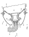
- Figure 1 shows the forward end of a combustor 10 of the type suitable for use in a gas turbine engine and including a hollow body 12 defining a combustion chamber 14 therein.
- the hollow body 12 is generally annular in form and is defined by an outer liner 16 and an inner liner 18.
- the upstream end of the hollow body 12 is substantially closed off by an outer cowl 20 attached to the outer liner 16 and an inner cowl 22 attached to the inner liner 18.
- An annular opening 24 is formed by the outer and inner cowls 20 and 22 for the introduction of fuel and compressed air.
- the compressed air is introduced into the combustor 10 from a compressor (not shown) in a direction generally indicated by arrow A of Figure 1.
- the compressed air passes primarily through the opening 24 to support combustion and partially into the region surrounding the hollow body 12 where it is used to cool both the liners 16 and 18 and turbomachinery further downstream.
- Figure 1 illustrates one preferred embodiment of a single annular combustor
- the present invention is equally applicable to other types of combustors, including double annular combustors and cannular combustors.
- each swirler assembly 28 Disposed between and interconnecting the outer and inner liners 16 and 18 near their upstream ends is an annular dome plate 26.
- a plurality of circumferentially spaced swirler assemblies 28 (one shown in Figure 1) is mounted in the dome plate 26.
- the forward end of each swirler assembly 28 includes a ferrule 30 that coaxially receives a corresponding fuel nozzle 32.
- Each fuel nozzle 32 includes a spray tip 34 disposed in the ferrule 30, a fuel tube 36 connected to the spray tip 34, and a substantially tubular housing 38 enclosing the spray tip 34 and the fuel tube 36.
- Fuel is carried through the fuel tube 36 to the spray tip 34 and discharged therefrom.
- the swirler assemblies 28 swirl air received via the annular opening 24. The swirling air interacts with fuel discharged from the spray tip 34 so that a thoroughly mixed fuel/air mixture flows into the combustion chamber 14.
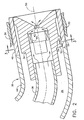
- FIG. 2 a first embodiment of the present invention is shown in detail.
- One end of the fuel tube 36 is inserted into a central opening in the forward end of the spray tip 34, which is substantially cylindrical in shape.
- a fuel swirler 40 is disposed inside of the spray tip 34, downstream of the end of the fuel tube 36.
- An orifice 42 is formed in the aft end of the spray tip 34.
- fuel is introduced through the fuel tube 36, swirled by the swirler 40, and then sprayed through the orifice 42.
- the configuration of the spray tip 34 as described thus far is merely one exemplary configuration used to illustrate the inventive concept. It should be understood that the present invention is not limited to fuel nozzles having this particular type of spray tip.
- a first row of tabs 52 is formed on the outer cylindrical surface of the spray tip 34.
- the first tabs 52 are located about the circumference of the spray tip 34 at the same axial position with respect to the central axis 50 and extend radially outwardly from the spray tip 34.
- a second row of outwardly extending tabs 54 is formed on the outer cylindrical surface of the spray tip 34 at a common axial position, which is spaced axially downstream from the first row of tabs 52.
- all tabs are preferably integrally formed with the spray tip 34, the term "formed on” is used herein to mean separately attached as well as integrally formed.
- Each of the two rows comprises an identical number of tabs, with corresponding tabs from each row being circumferentially aligned. That is, each second tab 54 is at the same circumferential location on the spray tip 34 as a corresponding one of the first tabs 52 so as to define an axial gap therebetween.
- a third row of tabs 56 is formed on the inner cylindrical surface of the wear sleeve 46.
- the third tabs 56 extend radially inwardly from the wear sleeve inner surface and are all located at a common axial position, which is situated between the axial positions of the first row of tabs 52 and the second row of tabs 54.
- the number of third tabs 56 is preferably equal to the number of first and second tabs 52 and 54.
- each third tab 56 and the corresponding first and/or second tab 52 and 54 there will be some axial space between each third tab 56 and the corresponding first and/or second tab 52 and 54 due to manufacturing tolerances.
- the configuration allows for normal or expected thermal growth of the housing 38 relative to the spray tip 34, axially and radially.
- the spray tip 34 is prevented from more than nominal movement with respect to the housing 38 in both the forward and aft axial directions that may be caused by excessive thermal growth, carbon jacking or other reasons. That is, the three rows of tabs 52,54,56 interact so as to constrain bi-directional axial movement of the spray tip 34 relative to the housing 38, thereby maintaining the proper axial positioning of the spray tip 34 with respect to the housing 38.
- Proper positioning of the spray tip 34 will reduce variation of fuel spray impingement location in the swirler assembly 28. This will result in improved performance and durability of the fuel nozzle 32 and the combustor 10.
- the third row contains three tabs 56 that are each approximately 60 degrees in width and are spaced equally around the circumference of the wear sleeve 46. Three spaces, which are also approximately 60 degrees in width, are accordingly defined between the tabs 56.
- the first and second tabs 52 and 54 are similarly configured on the spray tip 34. This arrangement permits assembly of the fuel nozzle 32 by placing the wear sleeve 46 over the aft end of the spray tip 34 and inserting the first tabs 52 through the circumferential spaces defined between the third tabs 56 so that the third tabs 56 are located at their axial position between the first and second tabs 52 and 54.
- the wear sleeve 46 is then rotated 60 degrees relative to the spray tip 34 so that each third tab 56 is disposed in a corresponding one of the gaps defined between the first and second tabs 52 and 54. Once it is properly positioned, the wear sleeve 46 is securely fixed to the primary section 44 of the housing 38. This prevents subsequent relative rotation of the spray tip 34 and the wear sleeve 46 so that all three rows of tabs 52,54,56 will remain circumferentially aligned.
- each tab row comprises two or more tabs.
- the present invention would theoretically work with one tab per row, using at least two equally spaced tabs per row will prevent any cocking of the spray tip 34 within the wear sleeve 46 that would result from a moment generated by unequal loads acting on the fuel nozzle 32.
- Figure 4 illustrates an alternative embodiment of the present invention.
- This embodiment functions in the same manner as the first embodiment, but the first row of tabs 52 and second row of tabs 54 are formed on the inner cylindrical surface of the wear sleeve 46 and extend radially inwardly therefrom.
- the third row of tabs 56 is formed on the outer cylindrical surface of the spray tip 34, and these tabs 56 extend radially outwardly therefrom.
- the first tabs 52 are all located at a common axial position with respect to the central axis 50
- the second tabs 54 are all located at another common axial position, which is spaced axially downstream from the first row of tabs 52.
- the third tabs 56 are all located at yet another common axial position, which is situated between the axial positions of the first row of tabs 52 and the second row of tabs 54. Each one of the third tabs 56 is disposed in a corresponding one of the gaps defined between the first and second tabs 52 and 54. As in the first embodiment, this configuration constrains bi-directional axial movement of the spray tip 34 relative to the housing 38 so as to maintain proper axial positioning, while allowing for normal or expected thermal growth of the housing 38 relative to the spray tip 34, both axially and radially.
Landscapes
- Engineering & Computer Science (AREA)
- Chemical & Material Sciences (AREA)
- Combustion & Propulsion (AREA)
- Mechanical Engineering (AREA)
- General Engineering & Computer Science (AREA)
- Fuel-Injection Apparatus (AREA)
- Nozzles For Spraying Of Liquid Fuel (AREA)
Description
- This invention relates generally to gas turbine engines and more particularly to a fuel nozzle for supplying fuel to the combustor of such engines.
- A gas turbine engine includes a compressor that provides pressurized air to a combustor wherein the air is mixed with fuel and burned for generating hot combustion gases. These gases flow downstream to one or more turbines that extract energy therefrom to power the compressor and provide useful work such as powering an aircraft in flight. In combustors used with aircraft engines, the fuel is supplied to the combustor through fuel nozzles positioned at one end of the combustion zone. A fuel nozzle typically includes a spray tip for precisely spraying fuel into a surrounding assembly, known as a swirler. The swirler also receives compressed air from the compressor and imparts a swirling motion to the air, thereby thoroughly mixing the fuel and air for combustion, see e.g. GB-A-2 328 386.
- Because the fuel nozzle is located in the compressor discharge gas stream, it is exposed to relatively high temperatures. The presence of high temperatures around the fuel nozzle can cause the fuel passing through the nozzle fuel tube to form granules of carbon on the inner walls thereof. The carbon or coke formation in the fuel tube may cause the fuel nozzle to become clogged. Excessive temperatures can also cause the fuel in the fuel nozzle to gum up, thereby further causing the fuel nozzle to become clogged. In addition, if the fuel becomes overheated, it may begin to vaporize in the inner passageway, thereby resulting in intermittent or non-continuous fuel delivery to the combustor.
- Consequently, conventional fuel nozzles typically include a heat shield in the form of a tubular housing that surrounds the fuel tube and spray tip so as to define an annular air gap therebetween. The air gap, or nozzle cavity, serves as a thermal barrier to protect the fuel in the fuel tube against coking.
- During engine operation, the temperature of the housing is greater than the temperature of the fuel tube resulting in differential thermal expansion. This differential growth can cause the spray tip to be axially displaced from its proper positioning with respect to the housing. Operational risks such as nozzle cavity over-pressurization and carbon jacking (i.e., the build-up of hard carbon on nozzle internal surfaces) can also lead to axial displacement of the spray tip relative to the housing.
- Such axial displacement can cause variations of the fuel spray impingement location in the swirler, which could impair the combustor exit temperature profile, engine emissions and engine start capability. Spray tip misalignment can also reduce the service life of the fuel nozzle, as well as the combustor, thereby increasing repair and maintenance costs. One known approach to preventing axial displacement is to use mechanical stops in the spray tip region to prevent axial motion of the spray tip in the aft direction. However, this approach does not address axial movement in the forward direction, which can also produce the above-mentioned problems.
- Accordingly, there is a need for a fuel nozzle that maintains the proper axial positioning of the spray tip relative to the housing in both the forward and aft directions.
- According to the present invention there is provided a fuel nozzle comprising:
- a spray tip;
- a housing coaxially disposed around said spray tip; and means for constraining bi-directional axial movement of said spray tip relative to said housing, wherein said means for constraining bi-directional axial movement comprises first and second tabs formed on one of said spray tip and said housing, and a third tab formed on the other of said spray tip and said housing, said third tab being disposed between said first and second tabs and said housing surrounding the entire axial extent of said spray tip.
-
- The above-mentioned need is met by the present invention which provides a fuel nozzle having a spray tip and a housing coaxially disposed around the spray tip. The fuel nozzle further includes a means for constraining bi-directional axial movement of the spray tip relative to the housing. The means for constraining bi-directional axial movement of the spray tip preferably includes first and second tabs formed on one of the housing and the spray tip and a third tab formed on the other one of the housing and the spray tip. The third tab is disposed between the first and second tabs to constrain bi-directional axial movement.
- The present invention and its advantages over the prior art will become apparent upon reading the following detailed description and the appended claims with reference to the accompanying drawings, in which:
- Figure 1 is an axial sectional view of the forward portion of a combustor having the fuel nozzle of the present invention.
- Figure 2 is an enlarged sectional view of a portion of the fuel nozzle of Figure 1.
- Figure 3 is a sectional view of the fuel nozzle housing taken along the line 3-3 of Figure 2.
- Figure 4 is an enlarged sectional view showing a portion of a fuel nozzle of an alternative embodiment of the present invention.
-
- Referring to the drawings wherein identical reference numerals denote the same elements throughout the various views, Figure 1 shows the forward end of a
combustor 10 of the type suitable for use in a gas turbine engine and including ahollow body 12 defining acombustion chamber 14 therein. Thehollow body 12 is generally annular in form and is defined by anouter liner 16 and aninner liner 18. The upstream end of thehollow body 12 is substantially closed off by anouter cowl 20 attached to theouter liner 16 and aninner cowl 22 attached to theinner liner 18. Anannular opening 24 is formed by the outer andinner cowls combustor 10 from a compressor (not shown) in a direction generally indicated by arrow A of Figure 1. The compressed air passes primarily through theopening 24 to support combustion and partially into the region surrounding thehollow body 12 where it is used to cool both theliners - It should be understood that although Figure 1 illustrates one preferred embodiment of a single annular combustor, the present invention is equally applicable to other types of combustors, including double annular combustors and cannular combustors.
- Disposed between and interconnecting the outer and
inner liners annular dome plate 26. A plurality of circumferentially spaced swirler assemblies 28 (one shown in Figure 1) is mounted in thedome plate 26. The forward end of eachswirler assembly 28 includes aferrule 30 that coaxially receives acorresponding fuel nozzle 32. Eachfuel nozzle 32 includes aspray tip 34 disposed in theferrule 30, afuel tube 36 connected to thespray tip 34, and a substantiallytubular housing 38 enclosing thespray tip 34 and thefuel tube 36. Fuel is carried through thefuel tube 36 to thespray tip 34 and discharged therefrom. The swirler assemblies 28 swirl air received via theannular opening 24. The swirling air interacts with fuel discharged from thespray tip 34 so that a thoroughly mixed fuel/air mixture flows into thecombustion chamber 14. - Referring now to Figure 2, a first embodiment of the present invention is shown in detail. One end of the
fuel tube 36 is inserted into a central opening in the forward end of thespray tip 34, which is substantially cylindrical in shape. As is known in the art, afuel swirler 40 is disposed inside of thespray tip 34, downstream of the end of thefuel tube 36. Anorifice 42 is formed in the aft end of thespray tip 34. In this configuration, fuel is introduced through thefuel tube 36, swirled by theswirler 40, and then sprayed through theorifice 42. The configuration of thespray tip 34 as described thus far is merely one exemplary configuration used to illustrate the inventive concept. It should be understood that the present invention is not limited to fuel nozzles having this particular type of spray tip. - The inner radius of the
housing 38 is sufficiently large so as to define an annular air gap ornozzle cavity 39 between thehousing 38 and thefuel tube 36 andspray tip 34. Thehousing 38 and thenozzle cavity 39 thus serve to protect thefuel tube 36 from the high temperatures to which thefuel nozzle 32 is exposed. Thehousing 38 includes aprimary section 44 and awear sleeve 46 attached to the distal end of theprimary section 44 by any suitable means such as welding or brazing. Thewear sleeve 46 is arranged coaxially (about a central axis 50) within theferrule 30, and the rear portion of thespray tip 34 is arranged coaxially within thewear sleeve 46. - A first row of
tabs 52 is formed on the outer cylindrical surface of thespray tip 34. Thefirst tabs 52 are located about the circumference of thespray tip 34 at the same axial position with respect to thecentral axis 50 and extend radially outwardly from thespray tip 34. Similarly, a second row of outwardly extendingtabs 54 is formed on the outer cylindrical surface of thespray tip 34 at a common axial position, which is spaced axially downstream from the first row oftabs 52. Although all tabs are preferably integrally formed with thespray tip 34, the term "formed on" is used herein to mean separately attached as well as integrally formed. Each of the two rows comprises an identical number of tabs, with corresponding tabs from each row being circumferentially aligned. That is, eachsecond tab 54 is at the same circumferential location on thespray tip 34 as a corresponding one of thefirst tabs 52 so as to define an axial gap therebetween. - A third row of
tabs 56 is formed on the inner cylindrical surface of thewear sleeve 46. Thethird tabs 56 extend radially inwardly from the wear sleeve inner surface and are all located at a common axial position, which is situated between the axial positions of the first row oftabs 52 and the second row oftabs 54. The number ofthird tabs 56 is preferably equal to the number of first andsecond tabs fuel nozzle 32 is assembled, each one of thethird tabs 56 is disposed in a corresponding one of the gaps defined between the first andsecond tabs - There will be some axial space between each
third tab 56 and the corresponding first and/orsecond tab housing 38 relative to thespray tip 34, axially and radially. However, thespray tip 34 is prevented from more than nominal movement with respect to thehousing 38 in both the forward and aft axial directions that may be caused by excessive thermal growth, carbon jacking or other reasons. That is, the three rows oftabs spray tip 34 relative to thehousing 38, thereby maintaining the proper axial positioning of thespray tip 34 with respect to thehousing 38. Proper positioning of thespray tip 34 will reduce variation of fuel spray impingement location in theswirler assembly 28. This will result in improved performance and durability of thefuel nozzle 32 and thecombustor 10. - As seen in Figure 3, the third row contains three
tabs 56 that are each approximately 60 degrees in width and are spaced equally around the circumference of thewear sleeve 46. Three spaces, which are also approximately 60 degrees in width, are accordingly defined between thetabs 56. The first andsecond tabs spray tip 34. This arrangement permits assembly of thefuel nozzle 32 by placing thewear sleeve 46 over the aft end of thespray tip 34 and inserting thefirst tabs 52 through the circumferential spaces defined between thethird tabs 56 so that thethird tabs 56 are located at their axial position between the first andsecond tabs wear sleeve 46 is then rotated 60 degrees relative to thespray tip 34 so that eachthird tab 56 is disposed in a corresponding one of the gaps defined between the first andsecond tabs wear sleeve 46 is securely fixed to theprimary section 44 of thehousing 38. This prevents subsequent relative rotation of thespray tip 34 and thewear sleeve 46 so that all three rows oftabs - Although the present invention is depicted in Figure 3 as having three third tabs 56 (and hence three first and
second tabs 52 and 54), it should be noted that the number of tabs per row is not limited to three. However, it is preferred that each tab row comprises two or more tabs. Although the present invention would theoretically work with one tab per row, using at least two equally spaced tabs per row will prevent any cocking of thespray tip 34 within thewear sleeve 46 that would result from a moment generated by unequal loads acting on thefuel nozzle 32. - Figure 4 illustrates an alternative embodiment of the present invention. This embodiment functions in the same manner as the first embodiment, but the first row of
tabs 52 and second row oftabs 54 are formed on the inner cylindrical surface of thewear sleeve 46 and extend radially inwardly therefrom. The third row oftabs 56 is formed on the outer cylindrical surface of thespray tip 34, and thesetabs 56 extend radially outwardly therefrom. As before, thefirst tabs 52 are all located at a common axial position with respect to thecentral axis 50, and thesecond tabs 54 are all located at another common axial position, which is spaced axially downstream from the first row oftabs 52. Thethird tabs 56 are all located at yet another common axial position, which is situated between the axial positions of the first row oftabs 52 and the second row oftabs 54. Each one of thethird tabs 56 is disposed in a corresponding one of the gaps defined between the first andsecond tabs spray tip 34 relative to thehousing 38 so as to maintain proper axial positioning, while allowing for normal or expected thermal growth of thehousing 38 relative to thespray tip 34, both axially and radially. - The foregoing has described a fuel nozzle in which bi-directional axial movement of the spray tip relative to the housing is constrained.
Claims (9)
- A fuel nozzle (32) comprising:means (52,54,56) for constraining bi-directional axial movement of said spray tip (34) relative to said housing (38), wherein said means for constraining bi-directional axial movement comprises first and second tabs (52, 54) formed on one of said spray tip (34) and said housing (38), and a third tab (56) formed on the other of said spray tip (34) and said housing (38), said third tab (56) being disposed between said first and second tabs (52, 54) and said housing surrounding the entire axial extent of said spray tip.a spray tip (34);a housing (38) coaxially disposed around said spray tip (34); and
- The fuel nozzle (32) of claim 1 wherein said means (52,54,56) for constraining bi-directional axial movement comprises first and second tabs (52,54) formed on one of said spray tip (34) and said housing (38), and a third tab (56) formed on the other of said spray tip (34) and said housing (38), said third tab (56) being disposed between said first and second tabs (52,54).
- The fuel nozzle (32) of claim 1 wherein said means (52,54,56) for constraining bi-directional axial movement comprises first and second rows of tabs (52,54) formed on one of said spray tip (34) and said housing (38), and a third row of tabs (56) formed on the other of said spray tip (34 and said housing (38), each tab of said third row of tabs (56) being disposed between a tab from said first row of tabs (52) and a tab from said second row of tabs (54).
- The fuel nozzle (32) of any one of claims 1 to 3 wherein said means (52,54,56) for constraining bi-directional axial movement allows for thermal growth of said housing (38) relative to said spray tip (34).
- The fuel nozzle (32) of claim 2 wherein said housing (38) is coaxially disposed around said spray tip (34).
- The fuel nozzle (32) of claim 2 wherein said first and second tabs (52,54) are spaced axially.
- The fuel nozzle (32) of claim 2 wherein said first, second and third tabs (52,54,56) are circumferentially aligned.
- The fuel nozzle (32) of claim 3 wherein said housing (38) comprises a primary section (44) and a wear sleeve (46), said third row of tabs (56) being formed on said wear sleeve (46).
- The fuel nozzle (32) of claim 8 wherein each tab of said first row of tabs (52) is spaced equally around said spray tip (34), each tab of said second row of tabs (54) is spaced equally around said spray tip (34), and each tab of said third row of tabs (56) is spaced equally around said wear sleeve (46).
Applications Claiming Priority (2)
| Application Number | Priority Date | Filing Date | Title |
|---|---|---|---|
| US466557 | 1999-12-17 | ||
| US09/466,557 US6460340B1 (en) | 1999-12-17 | 1999-12-17 | Fuel nozzle for gas turbine engine and method of assembling |
Publications (2)
| Publication Number | Publication Date |
|---|---|
| EP1108958A1 EP1108958A1 (en) | 2001-06-20 |
| EP1108958B1 true EP1108958B1 (en) | 2005-12-21 |
Family
ID=23852215
Family Applications (1)
| Application Number | Title | Priority Date | Filing Date |
|---|---|---|---|
| EP00311263A Expired - Lifetime EP1108958B1 (en) | 1999-12-17 | 2000-12-15 | Fuel nozzle for gas turbine engine and method of assembling |
Country Status (4)
| Country | Link |
|---|---|
| US (1) | US6460340B1 (en) |
| EP (1) | EP1108958B1 (en) |
| JP (1) | JP4695256B2 (en) |
| DE (1) | DE60024958T2 (en) |
Families Citing this family (30)
| Publication number | Priority date | Publication date | Assignee | Title |
|---|---|---|---|---|
| US6883332B2 (en) * | 1999-05-07 | 2005-04-26 | Parker-Hannifin Corporation | Fuel nozzle for turbine combustion engines having aerodynamic turning vanes |
| KR100380295B1 (en) * | 2001-02-14 | 2003-04-18 | 김동숙 | Portable gas torch |
| US6763663B2 (en) * | 2001-07-11 | 2004-07-20 | Parker-Hannifin Corporation | Injector with active cooling |
| US6755024B1 (en) * | 2001-08-23 | 2004-06-29 | Delavan Inc. | Multiplex injector |
| US6837056B2 (en) * | 2002-12-19 | 2005-01-04 | General Electric Company | Turbine inlet air-cooling system and method |
| US7013649B2 (en) * | 2004-05-25 | 2006-03-21 | General Electric Company | Gas turbine engine combustor mixer |
| US20060073348A1 (en) * | 2004-10-06 | 2006-04-06 | General Electric Company | Electroplated fuel nozzle/swirler wear coat |
| JP2006138566A (en) * | 2004-11-15 | 2006-06-01 | Hitachi Ltd | Gas turbine combustor and its liquid fuel injection nozzle |
| US7628019B2 (en) * | 2005-03-21 | 2009-12-08 | United Technologies Corporation | Fuel injector bearing plate assembly and swirler assembly |
| US7624576B2 (en) * | 2005-07-18 | 2009-12-01 | Pratt & Whitney Canada Corporation | Low smoke and emissions fuel nozzle |
| US20070189948A1 (en) * | 2006-02-14 | 2007-08-16 | Rocha Teresa G | Catalyst system and method |
| US8166763B2 (en) * | 2006-09-14 | 2012-05-01 | Solar Turbines Inc. | Gas turbine fuel injector with a removable pilot assembly |
| DE202008001547U1 (en) | 2007-07-24 | 2008-04-10 | Emcon Technologies Germany (Augsburg) Gmbh | Assembly for introducing a reducing agent into the exhaust pipe of an exhaust system of an internal combustion engine |
| US8286433B2 (en) * | 2007-10-26 | 2012-10-16 | Solar Turbines Inc. | Gas turbine fuel injector with removable pilot liquid tube |
| US8028512B2 (en) | 2007-11-28 | 2011-10-04 | Solar Turbines Inc. | Active combustion control for a turbine engine |
| US20100281868A1 (en) * | 2007-12-28 | 2010-11-11 | General Electric Company | Gas turbine engine combuster |
| US8061142B2 (en) * | 2008-04-11 | 2011-11-22 | General Electric Company | Mixer for a combustor |
| US8806871B2 (en) | 2008-04-11 | 2014-08-19 | General Electric Company | Fuel nozzle |
| US20090255120A1 (en) * | 2008-04-11 | 2009-10-15 | General Electric Company | Method of assembling a fuel nozzle |
| US8479519B2 (en) * | 2009-01-07 | 2013-07-09 | General Electric Company | Method and apparatus to facilitate cooling of a diffusion tip within a gas turbine engine |
| US10317081B2 (en) * | 2011-01-26 | 2019-06-11 | United Technologies Corporation | Fuel injector assembly |
| JP6240327B2 (en) | 2013-11-27 | 2017-11-29 | ゼネラル・エレクトリック・カンパニイ | Fuel nozzle having fluid lock and purge device |
| CA2933539C (en) | 2013-12-23 | 2022-01-18 | General Electric Company | Fuel nozzle with flexible support structures |
| CA2933536C (en) | 2013-12-23 | 2018-06-26 | General Electric Company | Fuel nozzle structure for air-assisted fuel injection |
| US20150345793A1 (en) * | 2014-06-03 | 2015-12-03 | Siemens Aktiengesellschaft | Fuel nozzle assembly with removable components |
| WO2016176076A1 (en) | 2015-04-30 | 2016-11-03 | Faurecia Emissions Control Technologies, Usa, Llc | Full rotation mixer |
| US20170122564A1 (en) * | 2015-10-29 | 2017-05-04 | General Electric Company | Fuel nozzle wall spacer for gas turbine engine |
| WO2018075061A1 (en) | 2016-10-21 | 2018-04-26 | Faurecia Emissions Control Technologies Usa, Llc | Reducing agent mixer |
| US10787946B2 (en) | 2018-09-19 | 2020-09-29 | Faurecia Emissions Control Technologies, Usa, Llc | Heated dosing mixer |
| CN109611888B (en) * | 2018-12-14 | 2021-03-26 | 中国航发沈阳发动机研究所 | Direct injection nozzle |
Family Cites Families (15)
| Publication number | Priority date | Publication date | Assignee | Title |
|---|---|---|---|---|
| FR985652A (en) | 1948-05-05 | 1951-07-23 | Rolls Royce | Improvements to sprayers for liquid fuel burners |
| US2762656A (en) * | 1951-10-11 | 1956-09-11 | Reginald P Fraser | Liquid atomizer |
| US2836234A (en) * | 1955-11-25 | 1958-05-27 | Texaco Development Corp | Annulus type burner for the production of synthesis gas |
| JPS53147118A (en) * | 1977-05-27 | 1978-12-21 | Hitachi Ltd | Fuel injection nozzle |
| US4154056A (en) * | 1977-09-06 | 1979-05-15 | Westinghouse Electric Corp. | Fuel nozzle assembly for a gas turbine engine |
| US4258544A (en) * | 1978-09-15 | 1981-03-31 | Caterpillar Tractor Co. | Dual fluid fuel nozzle |
| JPS63104817U (en) * | 1986-12-25 | 1988-07-07 | ||
| CA2039681C (en) * | 1990-04-05 | 2001-02-20 | Richard J. Hamilton | Quick disconnect nozzle assembly |
| US5247790A (en) * | 1992-09-18 | 1993-09-28 | Westinghouse Electric Corp. | Gas turbine fuel nozzle with replaceable cap |
| US5423178A (en) * | 1992-09-28 | 1995-06-13 | Parker-Hannifin Corporation | Multiple passage cooling circuit method and device for gas turbine engine fuel nozzle |
| JPH08145363A (en) * | 1994-11-21 | 1996-06-07 | Tokyo Electric Power Co Inc:The | Gas turbine combustor for liquid fuel |
| US5727739A (en) * | 1995-03-03 | 1998-03-17 | Spraying Systems Co. | Nozzle with quick disconnect spray tip |
| GB2328386B (en) | 1995-03-03 | 1999-07-21 | Spraying Systems Co | Nozzle with quick disconnect spray tip |
| US5761907A (en) * | 1995-12-11 | 1998-06-09 | Parker-Hannifin Corporation | Thermal gradient dispersing heatshield assembly |
| DE19645961A1 (en) * | 1996-11-07 | 1998-05-14 | Bmw Rolls Royce Gmbh | Fuel injector for a gas turbine combustor with a liquid cooled injector |
-
1999
- 1999-12-17 US US09/466,557 patent/US6460340B1/en not_active Expired - Lifetime
-
2000
- 2000-12-15 DE DE60024958T patent/DE60024958T2/en not_active Expired - Lifetime
- 2000-12-15 JP JP2000381166A patent/JP4695256B2/en not_active Expired - Fee Related
- 2000-12-15 EP EP00311263A patent/EP1108958B1/en not_active Expired - Lifetime
Also Published As
| Publication number | Publication date |
|---|---|
| EP1108958A1 (en) | 2001-06-20 |
| JP4695256B2 (en) | 2011-06-08 |
| DE60024958T2 (en) | 2006-09-28 |
| JP2001215015A (en) | 2001-08-10 |
| US6460340B1 (en) | 2002-10-08 |
| DE60024958D1 (en) | 2006-01-26 |
Similar Documents
| Publication | Publication Date | Title |
|---|---|---|
| EP1108958B1 (en) | Fuel nozzle for gas turbine engine and method of assembling | |
| US6761035B1 (en) | Thermally free fuel nozzle | |
| EP1253379B1 (en) | Methods and apparatus for cooling gas turbine engine combustors | |
| EP0800038B1 (en) | Nozzle for diffusion and premix combustion in a turbine | |
| EP1253380B1 (en) | Methods and apparatus for cooling gas turbine engine combustors | |
| US6622488B2 (en) | Pure airblast nozzle | |
| JP4641648B2 (en) | Modular combustor dome | |
| US7596949B2 (en) | Method and apparatus for heat shielding gas turbine engines | |
| US8015815B2 (en) | Fuel injector nozzles, with labyrinth grooves, for gas turbine engines | |
| EP1258681B1 (en) | Methods and apparatus for cooling gas turbine engine combustors | |
| JP7195775B2 (en) | Nozzle assembly for dual fuel fuel nozzles | |
| US12044411B2 (en) | Combustor having fuel sweeping structures | |
| WO2003001042A1 (en) | Means for wear reduction in a gas turbine combustor | |
| JP7139162B2 (en) | Dual fuel fuel nozzle with gaseous and liquid fuel capabilities | |
| EP4105557B1 (en) | Combustor having fuel sweeping structures | |
| EP2045527B1 (en) | Faceted dome assemblies for gas turbine engine combustors | |
| EP4067746B1 (en) | Combustor having a wake energizer | |
| Glynn et al. | Modular combustor dome | |
| AU2002247476A1 (en) | Means for wear reduction in a gas turbine combustor |
Legal Events
| Date | Code | Title | Description |
|---|---|---|---|
| PUAI | Public reference made under article 153(3) epc to a published international application that has entered the european phase |
Free format text: ORIGINAL CODE: 0009012 |
|
| AK | Designated contracting states |
Kind code of ref document: A1 Designated state(s): DE FR GB IT |
|
| AX | Request for extension of the european patent |
Free format text: AL;LT;LV;MK;RO;SI |
|
| 17P | Request for examination filed |
Effective date: 20011220 |
|
| AKX | Designation fees paid |
Free format text: DE FR GB IT |
|
| 17Q | First examination report despatched |
Effective date: 20041028 |
|
| GRAP | Despatch of communication of intention to grant a patent |
Free format text: ORIGINAL CODE: EPIDOSNIGR1 |
|
| GRAS | Grant fee paid |
Free format text: ORIGINAL CODE: EPIDOSNIGR3 |
|
| GRAA | (expected) grant |
Free format text: ORIGINAL CODE: 0009210 |
|
| AK | Designated contracting states |
Kind code of ref document: B1 Designated state(s): DE FR GB IT |
|
| PG25 | Lapsed in a contracting state [announced via postgrant information from national office to epo] |
Ref country code: IT Free format text: LAPSE BECAUSE OF FAILURE TO SUBMIT A TRANSLATION OF THE DESCRIPTION OR TO PAY THE FEE WITHIN THE PRESCRIBED TIME-LIMIT;WARNING: LAPSES OF ITALIAN PATENTS WITH EFFECTIVE DATE BEFORE 2007 MAY HAVE OCCURRED AT ANY TIME BEFORE 2007. THE CORRECT EFFECTIVE DATE MAY BE DIFFERENT FROM THE ONE RECORDED. Effective date: 20051221 |
|
| REG | Reference to a national code |
Ref country code: GB Ref legal event code: FG4D |
|
| REF | Corresponds to: |
Ref document number: 60024958 Country of ref document: DE Date of ref document: 20060126 Kind code of ref document: P |
|
| ET | Fr: translation filed | ||
| PLBE | No opposition filed within time limit |
Free format text: ORIGINAL CODE: 0009261 |
|
| STAA | Information on the status of an ep patent application or granted ep patent |
Free format text: STATUS: NO OPPOSITION FILED WITHIN TIME LIMIT |
|
| 26N | No opposition filed |
Effective date: 20060922 |
|
| PGRI | Patent reinstated in contracting state [announced from national office to epo] |
Ref country code: IT Effective date: 20091201 |
|
| REG | Reference to a national code |
Ref country code: FR Ref legal event code: PLFP Year of fee payment: 16 |
|
| PGFP | Annual fee paid to national office [announced via postgrant information from national office to epo] |
Ref country code: GB Payment date: 20151229 Year of fee payment: 16 |
|
| PGFP | Annual fee paid to national office [announced via postgrant information from national office to epo] |
Ref country code: FR Payment date: 20151217 Year of fee payment: 16 |
|
| PGFP | Annual fee paid to national office [announced via postgrant information from national office to epo] |
Ref country code: DE Payment date: 20151229 Year of fee payment: 16 |
|
| PG25 | Lapsed in a contracting state [announced via postgrant information from national office to epo] |
Ref country code: IT Free format text: LAPSE BECAUSE OF FAILURE TO SUBMIT A TRANSLATION OF THE DESCRIPTION OR TO PAY THE FEE WITHIN THE PRESCRIBED TIME-LIMIT Effective date: 20151215 |
|
| REG | Reference to a national code |
Ref country code: DE Ref legal event code: R119 Ref document number: 60024958 Country of ref document: DE |
|
| GBPC | Gb: european patent ceased through non-payment of renewal fee |
Effective date: 20161215 |
|
| PG25 | Lapsed in a contracting state [announced via postgrant information from national office to epo] |
Ref country code: IT Free format text: LAPSE BECAUSE OF FAILURE TO SUBMIT A TRANSLATION OF THE DESCRIPTION OR TO PAY THE FEE WITHIN THE PRESCRIBED TIME-LIMIT Effective date: 20151215 |
|
| PGFP | Annual fee paid to national office [announced via postgrant information from national office to epo] |
Ref country code: IT Payment date: 20151222 Year of fee payment: 16 |
|
| PGRI | Patent reinstated in contracting state [announced from national office to epo] |
Ref country code: IT Effective date: 20170710 |
|
| REG | Reference to a national code |
Ref country code: FR Ref legal event code: ST Effective date: 20170831 |
|
| PG25 | Lapsed in a contracting state [announced via postgrant information from national office to epo] |
Ref country code: FR Free format text: LAPSE BECAUSE OF NON-PAYMENT OF DUE FEES Effective date: 20170102 Ref country code: IT Free format text: LAPSE BECAUSE OF FAILURE TO SUBMIT A TRANSLATION OF THE DESCRIPTION OR TO PAY THE FEE WITHIN THE PRESCRIBED TIME-LIMIT Effective date: 20161215 |
|
| PGRI | Patent reinstated in contracting state [announced from national office to epo] |
Ref country code: IT Effective date: 20170710 |
|
| PG25 | Lapsed in a contracting state [announced via postgrant information from national office to epo] |
Ref country code: DE Free format text: LAPSE BECAUSE OF NON-PAYMENT OF DUE FEES Effective date: 20170701 Ref country code: GB Free format text: LAPSE BECAUSE OF NON-PAYMENT OF DUE FEES Effective date: 20161215 |