EP0376136A2 - Schmiedewerkzeug - Google Patents
Schmiedewerkzeug Download PDFInfo
- Publication number
- EP0376136A2 EP0376136A2 EP89123511A EP89123511A EP0376136A2 EP 0376136 A2 EP0376136 A2 EP 0376136A2 EP 89123511 A EP89123511 A EP 89123511A EP 89123511 A EP89123511 A EP 89123511A EP 0376136 A2 EP0376136 A2 EP 0376136A2
- Authority
- EP
- European Patent Office
- Prior art keywords
- die
- cylinder
- tool
- head
- swaging
- Prior art date
- Legal status (The legal status is an assumption and is not a legal conclusion. Google has not performed a legal analysis and makes no representation as to the accuracy of the status listed.)
- Granted
Links
Images
Classifications
-
- B—PERFORMING OPERATIONS; TRANSPORTING
- B21—MECHANICAL METAL-WORKING WITHOUT ESSENTIALLY REMOVING MATERIAL; PUNCHING METAL
- B21K—MAKING FORGED OR PRESSED METAL PRODUCTS, e.g. HORSE-SHOES, RIVETS, BOLTS OR WHEELS
- B21K5/00—Making tools or tool parts, e.g. pliers
-
- B—PERFORMING OPERATIONS; TRANSPORTING
- B21—MECHANICAL METAL-WORKING WITHOUT ESSENTIALLY REMOVING MATERIAL; PUNCHING METAL
- B21D—WORKING OR PROCESSING OF SHEET METAL OR METAL TUBES, RODS OR PROFILES WITHOUT ESSENTIALLY REMOVING MATERIAL; PUNCHING METAL
- B21D39/00—Application of procedures in order to connect objects or parts, e.g. coating with sheet metal otherwise than by plating; Tube expanders
- B21D39/04—Application of procedures in order to connect objects or parts, e.g. coating with sheet metal otherwise than by plating; Tube expanders of tubes with tubes; of tubes with rods
- B21D39/046—Connecting tubes to tube-like fittings
-
- B—PERFORMING OPERATIONS; TRANSPORTING
- B21—MECHANICAL METAL-WORKING WITHOUT ESSENTIALLY REMOVING MATERIAL; PUNCHING METAL
- B21D—WORKING OR PROCESSING OF SHEET METAL OR METAL TUBES, RODS OR PROFILES WITHOUT ESSENTIALLY REMOVING MATERIAL; PUNCHING METAL
- B21D39/00—Application of procedures in order to connect objects or parts, e.g. coating with sheet metal otherwise than by plating; Tube expanders
Definitions
- This invention relates to a swaging tool for use in swaging hydraulic fittings and the like.
- Swaged hydraulic fittings for use in connecting tubes in hydraulic systems have been used for many years, especially in the aircraft industry.
- the tubes are inserted into a fitting usually comprising a cylindrical sleeve, and then the fitting is swaged with a swaging tool to produce a fluid-tight connection between the tubes.
- the fitting is compressed radially inwardly by the swaging tool. This causes annular ridges on the outer surface of the fitting to be flattened and transferred to its inner surface. As a result, annular indentations are formed in the tube, attaching it securely to the fitting.
- the present invention provides a swaging tool for use in swaging hydraulic fittings and the like to join two tubes together.
- the two-piece design of the tool in combination with other features described below, contributes to a swaging tool that is extremely compact and lightweight, thus enabling the effective swaging of fittings in cramped quarters and difficult-to-access areas.
- the swaging tool of the present invention furthermore is intended to be simple to operate, reliable in use and less costly to manufacture.
- the swaging tool comprises a lower die adapted to be moved toward an upper die to swage a workpiece therebetween.
- a head of the tool holds the first die stationary with respect to the movable second die during swaging, with the second die being supported by a die holder having its base attached to the tool cylinder.
- the head is connected directly to the cylinder by a pair of tongues on the head adapted to be moved into sliding engagement with a pair of grooves on the cylinder.
- the tongues and grooves extend in a direction substantially transverse to the longitudinal axis of the cylinder, thus enabling rapid assembly and disassembly of the head with respect to the cylinder.
- the tool further includes provisions for aligning the dies with respect to each other.
- One of these provisions comprises head alignment means in the form of a rib extending along the length of one of the grooves and a trough extending along the length of a corresponding tongue. During assembly of the head to the cylinder, the rib moves into sliding engagement with the trough.
- This alignment feature prevents the head from being assembled to the cylinder in a reverse orientation, thereby ensuring that the upper die will be in a proper orientation with respect to the lower die.
- Another die aligning feature comprises a pin connected to the cylinder and projecting from its upper surface at a predetermined location adapted to be received in a hole in the lower surface of the die holder.
- the die holder during assembly of the die holder to the cylinder, it may be properly assembled only one way. This ensures correct orientation of the dies with respect to each other and, further, tends to prevent rotation of the lower die in the die holder during swaging.
- the cylinder has an upwardly projecting tapered shoulder designed to abut against one end of the die holder to align it on the cylinder and inhibit undesirable rotation.
- a pair of pistons within the cylinder are adapted to move the lower die toward the upper die to swage the fitting.
- the cylinder is divided into upper and lower chambers by a partition. More specifically, an upper piston having a head reciprocally retained within the upper chamber has a rod slidably extending through a bore in the cylinder for connection to the lower die holder.
- a lower piston having a head reciprocally retained within the lower chamber has a rod slidably extending through a bore in the partition for abutment with a head of the upper piston.
- the two pistons are biased to a retracted position by a return spring, preferably comprising a plurality of stacked disc springs.
- the second piston also includes an axial bore for providing fluid communication between the upper and lower chambers when fluid is supplied to the cylinder to move the pistons and, thus, the lower die toward the upper die to swage a workpiece.
- the lower chamber of the cylinder further includes a cylindrical end cap opposite the partition for closing off the lower chamber.
- the end cap has external threads adapted for threaded engagement with internal threads on the lower chamber.
- the external threads on the cylinder end cap are tapered outwardly such that the outer diameter of the end cap increases in a direction away from the open end of the cap. These tapered threads provide improved load distribution as compared to threads made in the conventional constant-pitch manner.
- the root radius of the internal threads on the lower chamber also is enlarged, with the crest of the threads on the end cap being machined off. This enlarged root radius and machined crest helps to prevent tool breakage from thread failure.
- the dies are connected to the tool by die retainer plates at opposite ends of each die.
- the fasteners which secure the die retainer plates to the tool are provided with resilient means positioned between the plates and the fastener to allow for expansion of the fitting and movement of the plates during swaging without breaking off the fastener or damaging the plates.
- the resilient means comprises three Belleville washers positioned in series between the head of the fastener and the outer surface of its corresponding retainer plate.
- Additional features of the swaging tool include tool insertion guides to prevent damage to the tool components during assembly of the tool.
- These insertion guides comprise sleeves having chamfered openings which fit over, for example, the cylinder to facilitate insertion of the upper piston without damaging or otherwise nicking the piston against the tool cylinder.
- the tool also may be provided with a two-axis swivel for enabling the tool to be rotated in a plane coinciding with the axis of the cylinder, as well as enabling the tool to follow a cylindrical path around the axis of the swivel.
- the swivel allows the tool to be oriented at virtually any direction and greatly improves the ability of the tool to swage a fitting where space is limited.
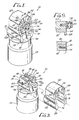
- the present invention is embodied in a swaging tool, indicated generally by the reference numeral 10, for use in swaging a fitting 12 and joining two tubes 14 and 16 together.
- the swaging tool comprises a lower die 18 adapted to be moved toward an upper die 20 to swage the fitting.
- the fitting 12 comprises a sleeve for receiving the ends of the two tubes 14 and 16 and, when swaged by the tool, for joining the two tubes together.
- the fitting 12 Before swaging, the fitting 12 has a smooth, cylindrical inner wall 22 and an irregularly shaped outer wall 24, as shown in the right portion of FIG. 2.
- the irregularly shaped outer wall 24 has an annular groove 26 of reduced diameter adjacent to each end of the fitting.
- the flat surface of the ridge 28 is designed to prevent relative rotation of the tube 16 and fitting 12 after the swaging has been completed.
- the fitting 12 is compressed inwardly by the dies 18 and 20 of the swaging tool 10 so that the fitting is given an irregular configuration along its inner wall 22 that grips the tube tightly.
- the left portion of FIG. 2 illustrates the fitting 12 after the swaging operation has been completed, with the annular ridge 28 having been forced inwardly to form an annular indentation 32 on the inner wall 22 of the fitting.
- the tube 14 is correspondingly swaged to a configuration matching the inner wall 22 of the fitting, thereby providing a permanent leak-proof coupling of the two tubes 14 and 16.
- the swaging tool 10 of this invention includes the pair of identical dies 18 and 20 comprising unitary members having slots extending inwardly from either end to allow radial compression of the dies.
- each die 18 and 20 has a curved surface 34 for receiving a portion of the fitting 12, including three parallel longitudinal slots 36 extending through the surface inwardly from the left end of the die to a location adjacent to the right end.
- the lower die 18 is mounted within a die holder 44 having an upper surface 46 with a central portion which is contoured as a substantially cylindrical segment 48 for receiving the curved die 18, and a tapered outer portion 49 on opposite sides of the central cylindrical segment 48 (also see FIG. 4).
- the die holder 44 also includes four planar sides 50 and a planar base 52 for connection to the tool cylinder 53.
- the lower die 18 is secured to the die holder 44 by a pair of flat die retainer plates 54 which engage the opposite flat end walls of the die holder.
- a pair of screws 56 at each end of the retainer plates 54 fastens the plates to the lower die 18.
- the central upper edges of the plates are provided with inwardly extending flanges 58 which over lap and fit against the beveled portions 42 at the ends of the lower die 18 to ensure that the lower die is retained securely by the die holder 44.
- the upper die 20 is received within a substantially U-shaped head 60.
- the head 60 has a substantially cylindrical central portion 62, similar to the central cylindrical segment 48 of the die holder 44, for receiving the curved upper die 20.
- a pair of tapered outer shoulders 63 on opposite sides of the cylindrical central portion 62 of the head 60 are adapted to mate with and engage the tapered outer portions 49 on the die holder 44 during the swaging operation.
- the angle of these tapered surfaces 49 and 63 with respect to the transverse axis of the tool 10 is about 30 o (see FIG. 4). In the prior art tools, these surfaces were horizontal and resulted in undesirably high stress concentration upon contact between the surfaces during swaging. This caused premature tool breakage.
- the prior art tool was reinforced in this area, which made it larger and heavier.
- the improved tapered tool surfaces 49 and 63 of the preferred embodiment result in substantially uniform stress distribution and, therefore, less likelihood of tool breakage.
- it advantageously allows the tool to be smaller and lighter because the tool 10 does not need to be reinforced in that area.
- a pair of die retainer plates 64 are connected to opposite ends of the head 60 by screws 66 for securing the upper die 20 within the head.
- Each of the upper die retainer plates 64 has an inwardly extending flange 68 which overlaps and fits against the beveled portions 42 at the ends of the upper die 20 to securely hold the die within the head 60.
- a special washer is interposed between the heads of the screws and the outer surface of the upper die retainer plates to prevent the screws from breaking or damage to the retainer plates caused by expansion of the fitting during the swaging operation.
- the head 60 has two parallel legs 70 extending from the tapered outer shoulders 63 and the central cylindrical portion 62. These legs 70 have flat, parallel inner and outer surfaces 72 and 74 which terminate in inwardly extending tongues 76 at their free ends.
- the tongues 76 have curved tips 78 and curved inner surfaces 80, and substantially flat, parallel outer surfaces 82 that are closer to each other than the flat, parallel outer surfaces 74 of the legs 70.
- the tongues 76 are adapted to be received within grooves 84 in the cylinder 53 having a configuration that matches the configuration of the tongues 76. These grooves 84 extend in a direction transverse to the longitudinal axis of the cylinder 53. To attach the head 60 directly to the cylinder 53, the ends of each tongue 76 are inserted with a sliding motion into the corresponding grooves 84 until the upper die 20 in the head 60 is aligned directly over the lower die 18.
- the tongue 76 and groove 84 attachment means of the head 60 and cylinder 53 described above advantageously enables a direct connection of the head to the cylinder.
- no intermediate posts, nuts or other components are needed to make the connection.
- This sliding and direct connection between the head 60 and cylinder 53 therefore eliminates several extra parts common to known prior art tools. This results in a more compact and lightweight tool, in terms of both axial tool length and overall tool diameter.
- the connection between the two components also is very secure and can be achieved rapidly. Further advantages of the sliding connection of the head 60 to the cylinder 53 are described below.
- head alignment means are provided for aligning the head 60 with respect to the cylinder 53 so that the head is connected to the cylinder in the proper orientation each time.
- Proper orientation of the head with respect to the cylinder is important because the upper and lower dies 20 and 18 carried by the head 60 and cylinder 53, respectively, must be in a correct orientation each time to ensure proper swaging of the fitting 12. If, for example, the upper die 20 is positioned in a reverse orientation with respect to the lower die 18, incomplete or improper swaging of the fitting 12 could occur.
- the head alignment means comprises a rib 86 extending preferably along the base of the groove 84 and a trough 88 extending preferably along the tip 78 of the corresponding tongue 76.
- the rib 86 is adapted to be received in the trough 86 as the tongue 76 moves into sliding engagement with the groove 84. Since the rib 86 and trough 88 combination is located on only one of the tongues 76 and its corresponding groove 84, it is impossible to reverse the orientation of the head 60, and thus the dies 18 and 20, when assembling the head 60 to the cylinder 53 to swage a fitting 12.
- the flat, parallel sides 50 of the die holder 44 fit substantially complimentary between the inner surfaces 72 of the legs 70 of the head 60.
- the die holder 44 is retained between the legs 70 by a ball 90 that fits within an opening 92 in the die holder biased outwardly by a spring 94 into a groove 96 in the inner surface 72 of the leg 70, as shown in FIG. 4.
- the groove 96 extends in an axial direction a sufficient distance to allow the lower die 18 and die holder 44 to move toward the upper die 20 during swaging while the head 60 and upper die 20 remain stationary.
- the base 52 of the die holder 44 abuts the upper surface 98 of the cylinder 53 and has a configuration that matches the base of the die holder.
- Another aspect of the swaging tool 10 of the present invention is the provision of means for aligning the lower die 18 and die holder 44 with respect to the cylinder 53 in the proper orientation.
- This lower die alignment means comprises a pin 100 connected to and projecting from the upper flat surface 98 of the cylinder 53 at a predetermined location. This location may be virtually anywhere on the cylinder upper surface 98, except of course at its center, and preferably, far enough away from the center to facilitate positioning of the die holder 44 onto the cylinder 53.
- a hole 102 is provided in the base 52 of the die holder 44 for receiving the pin 100 when the die holder is assembled onto the cylinder.
- the length of the pin 100 and the depth of the hole 102 are great enough so that as the die holder 44 is moved away from the cylinder 53 during swaging, the pin still will be completely within the hole.
- the hole 102 is located in the die holder base 52 such that when the pin 100 is received within the hole and the edges of the die holder base 52 are aligned with the edges of the cylinder top surface 98, the lower die 18 will be in the proper orientation on the cylinder 53.
- the pin 100 and hole 102 combination discussed above also prevents undesirable rotation of the die holder 44 with respect to the cylinder 53 which may occur during the swaging operation.
- a tapered shoulder 103 projecting from the upper flat surface 98 of the cylinder 53 is designed to abut against one end of the die holder 44 to prevent rotation of the die holder relative to the cylinder.
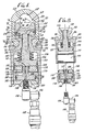
- This piston means is shown best in FIG. 4 and comprises a partition 104 in the cylinder 53 defining a first or upper cylinder chamber 106 and a second or lower cylinder chamber 108.
- the partition 104 is a cylindrical disk having a central axial hole 110.
- the outer circumferential edges of the partition 104 have an outwardly extending annular shoulder 112 which fits against an inwardly extending annular shoulder 114 on the inside surface of the cylinder marking the entrance to the upper chamber 106.
- the partition 104 is secured against the cylinder shoulder 114 between the two chambers 106 and 108 by the open end 116 of a cylindrical end cap 118 closing off the outer end of the cylinder 53.
- the open end 116 of the end cap 118 has an externally threaded outer surface 120 adapted for threaded engagement with an internally threaded surface 122 at the outer end of the cylinder 53 in the region of the lower chamber 108.
- a threaded hole 124 at the center of the end cap 118 permits the introduction of fluid to the cylinder 53 to allow pneumatic or hydraulic operation of the swaging tool 10, as desired. It also should be noted that the inner cylindrical surface of the end cap 118 is smooth and comprises the sidewall of the lower chamber 108.
- a double piston arrangement is provided in the cylinder 53, comprising a first or upper piston 126 in the upper chamber 106 and a second or lower piston 128 in the lower chamber 108.
- the upper piston 126 has a head 130 reciprocally retained within the upper chamber 106 and a rod 132 extending upwardly through an axial hole 134 in the cylinder 53 for connection to the die holder 44 carrying the lower die 18.
- the upper end of the rod 132 is received within a recess 136 in the die holder base 52 and is connected to it by a plurality of snap ring springs 138.
- a return spring 140 is positioned in the upper chamber 106 around the rod 132 and between the upper piston head 130 and the upper end of the upper chamber 106.
- the return spring 140 biases the upper piston 126 against the partition 104 in the absence of fluid pressure in the cylinder 53.
- the lower piston 128 has a cylindrical head 142 reciprocally retained within the lower chamber 108 and a rod 144 extending upwardly through the central axial hole 110 in the partition 104. The end of the lower piston rod 144 abuts the upper piston head 130.
- An axial passageway 146 extending completely through the lower piston 128 permits fluid communication between the lower chamber 108 and the upper chamber 106.
- the swaging tool 10 utilizes the double piston arrangement described above for enhanced force. Fluid enters the lower chamber 108 through the end cap hole 124 and travels through the passageway 146 to the region behind the upper piston 126.
- the passageway has a beveled entrance 148 to facilitate upward movement of the lower piston 128 during initial introduction of fluid.
- An annular recessed area 150 in the end cap 118 underneath the lower piston head 142 enables fluid to more rapidly build up behind the head to further facilitate upward piston movement.
- As the fluid reaches the upper piston 126 via the passageway 146 it initially builds up in a small area behind the head 130 and, upon upward movement of the lower piston 128, which in turn lifts the upper piston 126 from the partition 104, is then dispersed rapidly behind the entire head 130.
- the foregoing piston structure advantageously utilizes the entire surface area of the head of each piston. Importantly, this maximizes piston force without requiring any increase in fluid pressure. As a result, a smaller size piston arrangement may be employed, which translates into a more compact and lighter tool, in terms of overall tool diameter.
- a conventional helical spring was not the most suitable device for use as the return spring 140. Instead, it was found that a small stack of disc springs could carry the same load in much less space than a significantly larger helical spring.
- the stack of disc springs 140 in the present invention is smaller in diameter, lighter in weight, can carry higher loads and provides faster return of the upper piston 126 than a conventional helical spring. Again, this contributes to the reduced size and weight of the swaging tool 10 of this invention.
- the versatility of the swaging tool 10 is further enhanced by a two-axis swivel 152 threadedly connected to the base of the cylinder 53 at the internally threaded hole 124 in the end cap 118, as shown best in FIG. 4.
- the swivel 152 includes a first swivel joint 154 permitting the tool 10 to rotate in a plane that coincides with the axis of the cylinder 53.
- a second swivel joint 156 allows the tool 10 to follow a cylindrical path around the longitudinal axis of the swivel 152.
- the swivel 152 permits the tool 10 to be directed in practically any direction. This feature has special utility, for example, when swaging in cramped quarters or when direct axial access to the fitting 12 is not possible.
- the outer surfaces of the tongues 76 in the area where they engage the grooves 84 will become worn down and roughened during use of the tool 10 to indicate tool wear.
- This roughened area has been designated by the reference numeral 158 for purpose of reference.
- the area 158 is subject to being worn down and roughened by the limited amount of friction or rubbing that occurs between the tongues 76 and grooves 84 during swaging.
- the area 158 may be a signal to replace or repair certain components of the tool or, perhaps, the tool itself.
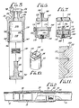
- FIGS. 5-6 Another advantage of the tool 10 of the present invention is its provision of tool insertion guides for preventing damage to the tool components during assembly of the tool.
- These tool insertion guides are shown in FIGS. 5-6 and facilitate assembly of the cylinder components of the tool in the manner shown in FIGS. 5-8.
- the first cylinder assembly step is shown in FIG. 5 and involves inserting the stack of disc springs 140 on the upper piston rod 132, and then inserting the upper piston 126 into the open end of the cylinder 53.
- the tool insertion guide 160 shown in FIG. 5 prevents the head 130 of the upper piston 126 from being damaged or nicked against the cylinder 53 upon its insertion.
- the tool insertion guide 160 comprises a substantially cylindrical sleeve having a thin walled inner end 162 adapted for insertion into and fitting against the internal threads 122 of the lower chamber 108.
- a thick walled outer end 164 of the insertion guide 160 extends out of the lower chamber 108 and over the open end of the cylinder 53.
- the entrance to the sleeve 160 at its outer end has a chamfered portion 166 to further facilitate insertion of the upper piston 126 into the cylinder 53.
- the inside diameter of the thin walled inner end 162 of the insertion guide 160 is substantially the same as the inner diameter of the upper chamber 106, so that a smooth transition is provided between the region defining the lower chamber 108 of the cylinder and the upper chamber 106 thereof.
- the insertion guide 160 may be constructed from free machined steel or other suitable materials which will not damage the upper piston 126. After insertion, the insertion guide 160 may be removed and retained for further use.
- the next step of assembling the cylinder components of the tool 10 is shown in FIG. 6, and involves inserting the lower piston 128 into the open end 116 of the end cap 118.
- another tool insertion guide 168 facilitates this assembly process.
- the second tool insertion guide 168 comprises a substantially cylindrical sleeve adapted to be placed on the open end 116 of the externally threaded end cap 118.
- the inner diameter of the sleeve 168 is substantially the same as the inner diameter of the smooth walled interior of the end cap 118.
- the entrance to the insertion guide also has a chamfered portion 170 to further facilitate insertion of the lower piston 128 into the cylindrical end cap 118.
- the finally assembly step is shown in FIG. 8, in which the end cap 118 carrying the lower piston 128 and partition 104 is screwed into the cylinder 53 until the open end 116 of the end cap 118 has trapped the partition 104 against the inwardly extending shoulder 114 of the cylinder defining the entrance of the upper chamber 106.
- the two-axis swivel 152 may be connected to the cylinder end cap 118 and connected to appropriate hydraulic or pneumatic means (not shown) for providing fluid pressure to the tool 10.
- Yet another feature of the invention is the employment of tapered threads on the external threads 120 of the end cap 118. It is well known that a substantial improvement in thread load distribution can be obtained by tapering the thread of either a male or female threaded component in a proper fashion, as compared to the conventional constant-pitch manner.
- the tapered threads result in a substantial improvement in the strength of the threaded connection, especially ones that normally are conducive to brittle plastic flow and, thus, liable to result in brittle fractures, such as are encountered with dynamic loads in swaging tools.
- the external threads 120 on the cylindrical end cap 118 in the preferred embodiment are tapered outwardly such that the outer diameter of the end cap 118 increases in a direction away from the open end 116 of the end cap 118, with the internal threads 122 on the cylinder 53 being made in the conventional constant-pitch manner.
- modifications to the external threads 120 of the end cap 118 and the internal threads 122 on the cylinder 53 include providing the internal threads 122 on the cylinder 53 with a root radius 171 that is larger than the UNJ standard.
- the root radius 171 for the threads 122 on the cylinder 53 is between approximately 0.0175 and 0.020 inches, where the internal diameter in the area of the threads is approximately 2.375 inches.
- the UNJ standard root radius for such threads normally would be approximately 0.0125 to 0.0150 inches. Therefore, the root radius 171 of the preferred embodiment is approximately 40% percent greater than the usual root radius.
- a further modification involves machining off the crest 173 of the outwardly tapered external threads 120 on the end cap 118.
- a majority of the components of the tool 10 of this invention are constructed from high tensile strength materials, such as stainless steel or maraging steel, for example.
- These components include the lower die 18, upper die 20, die holder 44, tool cylinder 53, head 60, pin 100, partition 104, end cap 118, upper piston 126 and lower piston 128.
- the preferred method of manufacturing many of these components, such as the cylinder 53 and the head 60, is by an electric discharge machine (EDM).
- EDM electric discharge machine
- the die retainer plates 54 and 64 can be made from cold rolled steel, and the tool insertion guides 160 and 168 can be made from free machined steel.
- the return spring 140 can be made of spring steel.
- Operation of the swaging tool 10 is as follows.
- a fitting 12 to be swaged is positioned between the upper and lower dies 18 and 20, with the lower die 18 in the retracted position. This may be done by slidably removing the head 60 from the cylinder 53, positioning the fitting in the region of the lower die 18, and then replacing the head.
- the flanges 58 and 68 of the die retainer plates 54 and 64 have corners extending into the die opening which are engaged by the end of the fitting 12 as the fitting is put into final position before swaging.
- the retainer plates 54 and 64 act as stops that locate the fitting 12 in the proper position axially relative to the lower and upper dies 18 and 20.
- pressurized fluid is admitted into the cylinder 53 through the axial hole 124 in the end cap 118. As explained in detail above, this moves the pistons 126 and 128 upwardly and, thus, moves the lower die 18 toward the upper die 20. Compression of the dies 18 and 20 in this manner continues until the tapered surfaces 49 and 63 have contacted each other, after which the swaging operation is terminated.
- the fluid pressure is released and the return spring 140 moves the pistons 126 and 128 to their retracted positions, the fitting 12 may be removed from the tool 10 and the swaging operation is complete.
- the tool 10 is provided with resilient means positioned between the die retainer plates 54 and 64 and the screws 56 and 66 to allow for expansion of the fitting 12 during swaging without breaking off the screws or damaging the retainer plates.
- the resilient means preferably comprises at least one washer 172 positioned between the head 174 of the screw 66 and the outer surface of its corresponding retainer plate 64.
- the washer 172 comprises three Belleville washers arranged in series, as illustrated in FIG. 9.
- the Belleville washers 172 acts as a buffer permitting some movement of the plates with respect to the tool 10 and thereby substantially reduces the possibility of tool damage.
- the assembled tool 10 will be inserted directly onto the fitting 12 if one of the tubes 14 or 16 to be swaged has a free end to permit access in this manner.
- the simple two-piece head-cylinder direct sliding connection permits rapid assembly of the tool and is especially useful in swaging fittings in difficult-to-access locations. After swaging, the head 60 may be rapidly removed from the tool 10 to swage the next fitting.
- the swaging tool 10 of this invention is adapted to swage fittings 12 for connecting two tubes 14 and 16, especially fittings located in tight or difficult-to-access areas.
- Simple yet effective means are provided for ensuring proper connection, alignment and orientation of the upper die 20 with respect to the lower die 18, as well as other important features to facilitate use and assembly of the tool, thereby contributing to a much lighter and smaller swaging tool than heretofore developed.
Landscapes
- Mechanical Engineering (AREA)
- Engineering & Computer Science (AREA)
- Forging (AREA)
- Surgical Instruments (AREA)
- Adhesives Or Adhesive Processes (AREA)
- Organic Low-Molecular-Weight Compounds And Preparation Thereof (AREA)
- Transition And Organic Metals Composition Catalysts For Addition Polymerization (AREA)
- Pyrane Compounds (AREA)
- Acyclic And Carbocyclic Compounds In Medicinal Compositions (AREA)
- Dental Preparations (AREA)
- Massaging Devices (AREA)
- Automatic Tool Replacement In Machine Tools (AREA)
- Cold Cathode And The Manufacture (AREA)
Applications Claiming Priority (2)
| Application Number | Priority Date | Filing Date | Title |
|---|---|---|---|
| US29100388A | 1988-12-27 | 1988-12-27 | |
| US291003 | 2002-11-08 |
Publications (3)
| Publication Number | Publication Date |
|---|---|
| EP0376136A2 true EP0376136A2 (de) | 1990-07-04 |
| EP0376136A3 EP0376136A3 (de) | 1991-01-09 |
| EP0376136B1 EP0376136B1 (de) | 1996-02-21 |
Family
ID=23118423
Family Applications (1)
| Application Number | Title | Priority Date | Filing Date |
|---|---|---|---|
| EP89123511A Expired - Lifetime EP0376136B1 (de) | 1988-12-27 | 1989-12-20 | Schmiedewerkzeug |
Country Status (9)
| Country | Link |
|---|---|
| EP (1) | EP0376136B1 (de) |
| JP (1) | JP2923315B2 (de) |
| KR (1) | KR920009857B1 (de) |
| AT (1) | ATE134322T1 (de) |
| AU (1) | AU623827B2 (de) |
| CA (1) | CA1320653C (de) |
| DE (1) | DE68925722T2 (de) |
| DK (1) | DK173008B1 (de) |
| NO (1) | NO180035C (de) |
Cited By (5)
| Publication number | Priority date | Publication date | Assignee | Title |
|---|---|---|---|---|
| WO2006122138A1 (en) * | 2005-05-09 | 2006-11-16 | Designed Metal Connections | Improved swaging tool |
| EP1789229A4 (de) * | 2004-09-17 | 2012-01-18 | Lokring Technology Llc | Installationswerkzeuganordnung |
| GB2522241A (en) * | 2014-01-20 | 2015-07-22 | Airbus Operations Ltd | Protection device |
| CN108380766A (zh) * | 2018-02-20 | 2018-08-10 | 中舟海洋科技(上海)有限公司 | 径向挤压式接头的便携式挤压装置 |
| CN119870356A (zh) * | 2025-03-12 | 2025-04-25 | 南京钢铁集团冶金铸造有限公司 | 一种锻件冷挤压成型装置 |
Families Citing this family (4)
| Publication number | Priority date | Publication date | Assignee | Title |
|---|---|---|---|---|
| KR101246543B1 (ko) * | 2004-02-24 | 2013-04-01 | 록링 테크놀로지 코포레이션 | 유압식 수동 공구 |
| DE102010000545A1 (de) * | 2010-02-25 | 2011-08-25 | Joiner's Bench GmbH, 42859 | Hydraulische Pressvorrichtung |
| JP6085483B2 (ja) | 2013-01-24 | 2017-02-22 | 三菱重工業株式会社 | スエージ装置及びスエージ方法 |
| KR101777151B1 (ko) * | 2015-02-12 | 2017-09-14 | 배상율 | 스웨징금형 |
Family Cites Families (8)
| Publication number | Priority date | Publication date | Assignee | Title |
|---|---|---|---|---|
| US3771343A (en) * | 1972-03-24 | 1973-11-13 | Mc Donnell Douglas Corp | Swaging tool |
| US3848451A (en) * | 1972-11-24 | 1974-11-19 | Deutsch Co Metal Components | Swaging tool |
| US3823597A (en) * | 1973-07-02 | 1974-07-16 | Mc Donnell Douglas Corp | Swaging tool die extender |
| GB1526222A (en) * | 1975-08-04 | 1978-09-27 | Ccl Systems Ltd | Swaging dies |
| CA1042638A (en) * | 1975-08-04 | 1978-11-21 | Cedric G. Birks | Swaging dies |
| FI63875C (fi) * | 1975-08-04 | 1983-09-12 | Ccl Systems Ltd | Press med vilken en matallhylsa anbringas pao en armeringsstaong eller vajer |
| US4276765A (en) * | 1979-06-14 | 1981-07-07 | Rikizo Yoneda | Pressing device for a hose coupler |
| US4528740A (en) * | 1983-04-18 | 1985-07-16 | Msw Corporation | Shrink ring clamp assembly |
-
1989
- 1989-09-25 CA CA000612916A patent/CA1320653C/en not_active Expired - Lifetime
- 1989-10-10 NO NO894054A patent/NO180035C/no unknown
- 1989-12-06 JP JP1317414A patent/JP2923315B2/ja not_active Expired - Lifetime
- 1989-12-20 DE DE68925722T patent/DE68925722T2/de not_active Expired - Lifetime
- 1989-12-20 EP EP89123511A patent/EP0376136B1/de not_active Expired - Lifetime
- 1989-12-20 AT AT89123511T patent/ATE134322T1/de not_active IP Right Cessation
- 1989-12-21 AU AU47086/89A patent/AU623827B2/en not_active Expired
- 1989-12-22 DK DK198906585A patent/DK173008B1/da not_active IP Right Cessation
- 1989-12-26 KR KR1019890019480A patent/KR920009857B1/ko not_active Expired
Cited By (9)
| Publication number | Priority date | Publication date | Assignee | Title |
|---|---|---|---|---|
| EP1789229A4 (de) * | 2004-09-17 | 2012-01-18 | Lokring Technology Llc | Installationswerkzeuganordnung |
| WO2006122138A1 (en) * | 2005-05-09 | 2006-11-16 | Designed Metal Connections | Improved swaging tool |
| US7299674B2 (en) | 2005-05-09 | 2007-11-27 | Designed Metal Connections | Swaging tool |
| CN100560300C (zh) * | 2005-05-09 | 2009-11-18 | 工艺金属连接器公司 | 改进的旋锻工具 |
| GB2522241A (en) * | 2014-01-20 | 2015-07-22 | Airbus Operations Ltd | Protection device |
| EP2896468A3 (de) * | 2014-01-20 | 2015-11-18 | Airbus Operations Limited | Schutzvorrichtung |
| CN108380766A (zh) * | 2018-02-20 | 2018-08-10 | 中舟海洋科技(上海)有限公司 | 径向挤压式接头的便携式挤压装置 |
| CN119870356A (zh) * | 2025-03-12 | 2025-04-25 | 南京钢铁集团冶金铸造有限公司 | 一种锻件冷挤压成型装置 |
| CN119870356B (zh) * | 2025-03-12 | 2025-12-02 | 南京钢铁集团冶金铸造有限公司 | 一种锻件冷挤压成型装置 |
Also Published As
| Publication number | Publication date |
|---|---|
| JP2923315B2 (ja) | 1999-07-26 |
| EP0376136B1 (de) | 1996-02-21 |
| DK173008B1 (da) | 1999-11-08 |
| KR920009857B1 (ko) | 1992-11-02 |
| DE68925722T2 (de) | 1996-07-04 |
| CA1320653C (en) | 1993-07-27 |
| ATE134322T1 (de) | 1996-03-15 |
| AU623827B2 (en) | 1992-05-21 |
| JPH02182329A (ja) | 1990-07-17 |
| NO894054D0 (no) | 1989-10-10 |
| EP0376136A3 (de) | 1991-01-09 |
| NO180035B (no) | 1996-10-28 |
| AU4708689A (en) | 1990-07-05 |
| DK658589A (da) | 1990-06-28 |
| DK658589D0 (da) | 1989-12-22 |
| NO180035C (no) | 1997-02-05 |
| NO894054L (no) | 1990-06-28 |
| DE68925722D1 (de) | 1996-03-28 |
| KR900009180A (ko) | 1990-07-02 |
Similar Documents
| Publication | Publication Date | Title |
|---|---|---|
| US5069058A (en) | Swaging tool | |
| US5404631A (en) | Method of extracting a bushing from a bore | |
| US3848451A (en) | Swaging tool | |
| EP0376136B1 (de) | Schmiedewerkzeug | |
| JPH0724912B2 (ja) | 雄円錐ネジ形成方法およびそれに用いる装置 | |
| US4634153A (en) | Reusable hose fitting | |
| US5918498A (en) | Dummy block construction | |
| US9737982B2 (en) | Pinned head swage tool | |
| US5361473A (en) | Rivet setting anvil | |
| EP1879723B1 (de) | Verbessertes senkwerkzeug | |
| US20060090318A1 (en) | Self-aligning tool for installation of pull type fastener | |
| CN116079093A (zh) | 定子车外圆用的内涨夹具 | |
| WO1993024780A1 (en) | Multiple-piece externally swagable fitting | |
| US6769283B2 (en) | Swaging device | |
| US6912776B2 (en) | Pierce nut installation apparatus | |
| US3693399A (en) | Fastener installation and crimping tool | |
| US5189780A (en) | Rivet setting anvil | |
| CN120461921B (zh) | 一种胶囊夹具 | |
| US7581300B2 (en) | Method for the attachment of a functional element | |
| US20240313495A1 (en) | Crimping unit for a crimping tool | |
| US4453302A (en) | Apparatus for reusing high pressure hose fittings | |
| HK1122242B (en) | Improved swaging tool | |
| SU1162530A1 (ru) | Устройство дл обжати муфт на концах шлангов |
Legal Events
| Date | Code | Title | Description |
|---|---|---|---|
| PUAI | Public reference made under article 153(3) epc to a published international application that has entered the european phase |
Free format text: ORIGINAL CODE: 0009012 |
|
| AK | Designated contracting states |
Kind code of ref document: A2 Designated state(s): AT BE CH DE FR GB IT LI NL SE |
|
| PUAL | Search report despatched |
Free format text: ORIGINAL CODE: 0009013 |
|
| AK | Designated contracting states |
Kind code of ref document: A3 Designated state(s): AT BE CH DE FR GB IT LI NL SE |
|
| 17P | Request for examination filed |
Effective date: 19910223 |
|
| 17Q | First examination report despatched |
Effective date: 19920330 |
|
| GRAA | (expected) grant |
Free format text: ORIGINAL CODE: 0009210 |
|
| AK | Designated contracting states |
Kind code of ref document: B1 Designated state(s): AT BE CH DE FR GB IT LI NL SE |
|
| PG25 | Lapsed in a contracting state [announced via postgrant information from national office to epo] |
Ref country code: LI Effective date: 19960221 Ref country code: CH Effective date: 19960221 Ref country code: AT Effective date: 19960221 |
|
| REF | Corresponds to: |
Ref document number: 134322 Country of ref document: AT Date of ref document: 19960315 Kind code of ref document: T |
|
| ITF | It: translation for a ep patent filed | ||
| REF | Corresponds to: |
Ref document number: 68925722 Country of ref document: DE Date of ref document: 19960328 |
|
| ET | Fr: translation filed | ||
| REG | Reference to a national code |
Ref country code: CH Ref legal event code: PL |
|
| PLBE | No opposition filed within time limit |
Free format text: ORIGINAL CODE: 0009261 |
|
| STAA | Information on the status of an ep patent application or granted ep patent |
Free format text: STATUS: NO OPPOSITION FILED WITHIN TIME LIMIT |
|
| 26N | No opposition filed | ||
| REG | Reference to a national code |
Ref country code: GB Ref legal event code: IF02 |
|
| REG | Reference to a national code |
Ref country code: FR Ref legal event code: TP |
|
| PGFP | Annual fee paid to national office [announced via postgrant information from national office to epo] |
Ref country code: NL Payment date: 20081111 Year of fee payment: 20 |
|
| PGFP | Annual fee paid to national office [announced via postgrant information from national office to epo] |
Ref country code: SE Payment date: 20081208 Year of fee payment: 20 Ref country code: IT Payment date: 20081212 Year of fee payment: 20 |
|
| PGFP | Annual fee paid to national office [announced via postgrant information from national office to epo] |
Ref country code: FR Payment date: 20081205 Year of fee payment: 20 |
|
| PGFP | Annual fee paid to national office [announced via postgrant information from national office to epo] |
Ref country code: DE Payment date: 20081230 Year of fee payment: 20 |
|
| PGFP | Annual fee paid to national office [announced via postgrant information from national office to epo] |
Ref country code: GB Payment date: 20081110 Year of fee payment: 20 |
|
| PGFP | Annual fee paid to national office [announced via postgrant information from national office to epo] |
Ref country code: BE Payment date: 20090112 Year of fee payment: 20 |
|
| BE20 | Be: patent expired |
Owner name: *THE DEUTSCH CY Effective date: 20091220 |
|
| REG | Reference to a national code |
Ref country code: GB Ref legal event code: PE20 Expiry date: 20091219 |
|
| NLV7 | Nl: ceased due to reaching the maximum lifetime of a patent |
Effective date: 20091220 |
|
| PG25 | Lapsed in a contracting state [announced via postgrant information from national office to epo] |
Ref country code: NL Free format text: LAPSE BECAUSE OF EXPIRATION OF PROTECTION Effective date: 20091220 |
|
| PG25 | Lapsed in a contracting state [announced via postgrant information from national office to epo] |
Ref country code: GB Free format text: LAPSE BECAUSE OF EXPIRATION OF PROTECTION Effective date: 20091219 |