EP0376015A2 - Welding torch with a shielding gas for arc welding with a consumable electrode - Google Patents
Welding torch with a shielding gas for arc welding with a consumable electrode Download PDFInfo
- Publication number
- EP0376015A2 EP0376015A2 EP89122602A EP89122602A EP0376015A2 EP 0376015 A2 EP0376015 A2 EP 0376015A2 EP 89122602 A EP89122602 A EP 89122602A EP 89122602 A EP89122602 A EP 89122602A EP 0376015 A2 EP0376015 A2 EP 0376015A2
- Authority
- EP
- European Patent Office
- Prior art keywords
- forced
- gas
- cooling
- tubes
- nozzle holder
- Prior art date
- Legal status (The legal status is an assumption and is not a legal conclusion. Google has not performed a legal analysis and makes no representation as to the accuracy of the status listed.)
- Granted
Links
Images
Classifications
-
- B—PERFORMING OPERATIONS; TRANSPORTING
- B23—MACHINE TOOLS; METAL-WORKING NOT OTHERWISE PROVIDED FOR
- B23K—SOLDERING OR UNSOLDERING; WELDING; CLADDING OR PLATING BY SOLDERING OR WELDING; CUTTING BY APPLYING HEAT LOCALLY, e.g. FLAME CUTTING; WORKING BY LASER BEAM
- B23K9/00—Arc welding or cutting
- B23K9/24—Features related to electrodes
- B23K9/28—Supporting devices for electrodes
- B23K9/29—Supporting devices adapted for making use of shielding means
- B23K9/291—Supporting devices adapted for making use of shielding means the shielding means being a gas
- B23K9/295—Supporting devices adapted for making use of shielding means the shielding means being a gas using consumable electrode-wire
Definitions
- the invention relates to a protective gas welding torch for arc welding with a melting electrode according to the preamble of claim 1 and as it has become known for example from DE-PS 32 40 715.
- the object of the invention is to improve the cooling and thus the service life of the protective gas nozzle and the parts connected to the protective gas nozzle in a protective gas welding torch of this type.
- both the gas nozzle holder and the current contact nozzle holder are directly cooled by the series-connected forced circuits for the cooling water.
- the burner trunk is completely cooled, which also leads to a cooler handle. It is now easily possible for a welder, e.g. B. in difficult welding positions to guide the torch with two hands, one hand can attack the "cold torch".
- the improved cooling also increases the service life of the burner consumables such as the protective gas nozzle and power contact nozzle, as well as the load capacity of the entire burner, without increasing the burner volume. Furthermore, the overall cooler burner reduces spatter adhesion.
- the shielding gas welding torch designated in its entirety in FIG. 1, has two concentric tubes 11, 12 carrying welding current.
- the inner tube 11 is used for welding protective gas supply and for electrode wire guidance, the melting wire electrode, not shown, for. B. in a wire spiral 13 (see FIG. 2) and in the intermediate space 14 between the wire spiral 13 and the inner tube 11 of the protective gas.
- the inner tube 11 forms a first forced circuit 15 for the cooling water with the outer tube 12, the inner and outer tubes 11 and 12 being fastened in a current contact nozzle carrier 16.
- the current contact nozzle carrier 16 is preferably connected to the tubes 11, 12 by soldering and assigned to the two tubes in such a way that the recess 18 provided in the circumference 17 of the carrier 16 forms the inner boundary for the water circulation ring channel 19.
- the outer tube 12 is surrounded concentrically by an electrical insulation 20, which preferably consists of a PTFE tube.
- the insulation 20 is surrounded concentrically by a jacket 21, at the end of which the current contact nozzle holder 16 is assigned a gas nozzle holder 22 is arranged.
- the jacket 21 has two concentrically arranged cooling tubes 24, 25 which are connected in the gas nozzle holder 22 by soldering.
- a cooling water circulation ring channel 27 is formed in connection with the recess 26, a cooling water circulation ring channel 27 is formed.
- a water supply 29 is connected to the inlet 28 of the second forced circuit 23, so that (see FIG.
- cooling water initially is guided via the outer cooling channels 39-47 to the cooling water circulation ring channel 27 in the gas nozzle carrier 22 and is conducted from there via the outer cooling channels 30-38 back to the outlet 48 of the second circuit 23.
- This outlet 48 is connected to the inlet 49 of the first forced circuit 15, so that the cooling water now flows through the two inner cooling channels 50, 51 to the water circulation ring channel 19 in the current contact nozzle carrier 16. From this, the cooling water is guided via the further inner cooling channels 52, 53 to the outlet 54 of the first forced circuit 15 and from there via the current-water return cable 55, for example to a water recooling device.
- This series connection of cooling water circuits first cools the gas nozzle holder 22 and thus indirectly the gas nozzle 56 fastened thereon and then directly the current contact nozzle holder 16 and thus indirectly the screwed-in contact nozzle 57, thereby achieving particularly intensive cooling of the welding torch mentioned.
- the inner tube 11 and the inner cooling tube 24 are designed as profile / finned tubes.
- the cross-sectional areas / flow cross-sections within the second forced circuit 23 are dimensioned the same, i. H. the sum of the flow cross sections of the cooling channels 30 - 38 corresponds to the flow cross section of the water circulation ring channel 19 and the sum of the flow cross sections 39 - 47.
- the flow cross sections of the first forced circuit 15 are dimensioned the same, ie the sum of the flow cross sections of the channels 50 and 51 corresponds to that Sum of the flow cross sections of the channels 52 and 53 and the cross section of the water circulation ring channel 19. This dimensioning achieves particularly good heat dissipation.
Landscapes
- Engineering & Computer Science (AREA)
- Physics & Mathematics (AREA)
- Plasma & Fusion (AREA)
- Mechanical Engineering (AREA)
- Arc Welding In General (AREA)
- Resistance Welding (AREA)
Abstract
Description
Die Erfindung betrifft einen Schutzgasschweißbrenner zum Lichtbogenschweißen mit abschmelzender Elektrode nach dem Oberbegriff des Anspruches 1 und wie er beispielsweise aus der DE-PS 32 40 715 bekannt geworden ist.The invention relates to a protective gas welding torch for arc welding with a melting electrode according to the preamble of claim 1 and as it has become known for example from DE-PS 32 40 715.
Der Erfindung liegt die Aufgabe zugrunde, bei einem Schutzgasschweißbrenner dieser Art die Kühlung und damit die Standzeit der Schutzgasdüse sowie die mit der Schutzgasdüse in Verbindung stehenden Teile zu verbessern.The object of the invention is to improve the cooling and thus the service life of the protective gas nozzle and the parts connected to the protective gas nozzle in a protective gas welding torch of this type.
Diese Aufgabe wird erfindungsgemäß durch die kenn zeichnenden Merkmale des Anspruches 1 gelöst.This object is achieved by the kenn Drawing features of claim 1 solved.
Weitere vorteilhafte Ausbildungen der Erfindung sind in den Unteransprüchen angegeben.Further advantageous developments of the invention are specified in the subclaims.
Die mit der Erfindung erzielten Vorteile bestehen insbesondere darin, daß durch die hintereinander geschalteten Zwangskreisläufe für das Kühlwasser sowohl der Gasdüsenträger als auch der Stromkontaktdüsenträger direkt gekühlt werden. Ferner erfolgt eine komplette Kühlung des Brennerrüssels, was auch zu einem kühleren Handgriff führt. Damit ist es einem Schweißer nunmehr ohne weiteres möglich, z. B. in schwierigen Schweißpositionen den Brenner mit zwei Händen zu führen, wobei eine Hand am "kalten Brennerrüssel" angreifen kann. Durch die verbesserte Kühlung erhöht sich somit auch die Standzeit der Brennerverschleißteile wie Schutzgasdüse und Stromkontaktdüse sowie die Belastbarkeit des gesamten Brenners, und zwar ohne Vergrößerung des Brennervolumens. Ferner wird durch den insgesamt kühleren Brenner die Spritzeranhaftung vermindert.The advantages achieved by the invention are, in particular, that both the gas nozzle holder and the current contact nozzle holder are directly cooled by the series-connected forced circuits for the cooling water. Furthermore, the burner trunk is completely cooled, which also leads to a cooler handle. It is now easily possible for a welder, e.g. B. in difficult welding positions to guide the torch with two hands, one hand can attack the "cold torch". The improved cooling also increases the service life of the burner consumables such as the protective gas nozzle and power contact nozzle, as well as the load capacity of the entire burner, without increasing the burner volume. Furthermore, the overall cooler burner reduces spatter adhesion.
Ein Ausführungsbeispiel der Erfindung ist in der Zeichnung dargestellt und wird im folgenden näher beschrieben. Es veranschaulicht
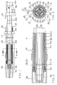
- Fig. 1 einen Schutzgasschweißbrenner mit gestrecktem Brennerrüssel, teilweise geschnitten
- Fig. 2 eine vergrößerte Darstellung der Einzelheit E in Fig. 1
- Fig. 3 einen Schnitt längs der Linie A-B in Fig. 1
- Fig. 1 shows a protective gas welding torch with an elongated torch, partially cut
- FIG. 2 is an enlarged view of detail E in FIG. 1
- 3 shows a section along the line AB in FIG. 1st
Der in Fig. 1 seiner Gesamtheit mit 10 bezeichnete Schutzgasschweißbrenner weist zwei konzentrische, schweißstromführende Rohre 11, 12 auf. Das Innenrohr 11 dient zur Schweißschutzgaszufuhr und zur Elektrodendrahtführung, wobei die nicht dargestellte abschmelzende Drahtelektrode z. B. in einer Drahtspirale 13 (s. Fig. 2) und im Zwischenraum 14 zwischen der Drahtspirale 13 und dem Innenrohr 11 des Schutzgases geführt werden.The shielding gas welding torch, designated in its entirety in FIG. 1, has two
Das Innenrohr 11 bildet mit dem Außenrohr 12 einen ersten Zwangskreislauf 15 für das Kühlwasser, wobei Innen- und Außenrohr 11 bzw. 12 in einem Stromkontaktdüsenträger 16 befestigt sind. Dabei ist bevorzugt der Stromkontaktdüsenträger 16 mit den Rohren 11, 12 durch Löten verbunden und derart den beiden Rohren zugeordnet, daß die im Umfang 17 des Trägers 16 vorgesehene Eindrehung 18 die innere Begrenzung für den Wasserumlaufringkanal 19 bildet.The
Das Außenrohr 12 wird von einer elektrischen Isolierung 20, die vorzugsweise aus einem PTFE-Schlauch besteht, konzentrisch umgeben. Die Isolierung 20 ist konzentrisch von einem Mantel 21 umgeben, an dessen dem Stromkontaktdüsenträger 16 zugeordneten Ende ein Gasdüsenträger 22 angeordnet ist. Der Mantel 21 weist zur Bildung eines zweiten Zwangskreislaufes 23 für das Kühlmittel zwei konzentrisch angeordnete Kühlrohre 24, 25 auf, die im Gasdüsenträger 22 durch Löten verbunden sind. In Verbindung mit der Ausdrehung 26 wird ein Kühlwasserumlaufringkanal 27 gebildet. An den Eingang 28 des zweiten Zwangskreislaufes 23 ist ein Wasservorlauf 29 angeschlossen, so daß (s. Fig. 2) Kühlwasser zunächst über die äußeren Kühlkanäle 39 - 47 zum Kühlwasserumlaufringkanal 27 im Gasdüsenträger 22 geführt wird und von diesem über die äußeren Kühlkanäle 30 - 38 zurück zum Ausgang 48 des zweiten Kreislaufs 23 geleitet wird. Dieser Ausgang 48 ist mit dem Eingang 49 des ersten Zwangskreislaufes 15 verbunden, so daß das Kühlwasser nunmehr durch die beiden inneren Kühlkanäle 50, 51 zum Wasserumlaufringkanal 19 im Stromkontaktdüsenträger 16 strömt. Von diesem wird das Kühlwasser über die weiteren inneren Kühlkanäle 52, 53 zum Ausgang 54 des ersten Zwangskreislaufes 15 geführt und von diesem über das Strom-Wasserrücklaufkabel 55, beispielsweise zu einem Wasserrückkühlgerät, geleitet.The
Durch diese Hintereinanderschaltung von Kühlwasserkreisläufen wird zunächst direkt der Gasdüsenträger 22 und damit indirekt die hierauf befestigte Gasdüse 56 und anschließend direkt der Stromkontaktdüsenträger 16 und somit indirekt die eingeschraubte Kontaktdüse 57 gekühlt, wodurch eine besonders intensive Kühlung des genannten Schweißbrenners erreicht wird. Zur Erzielung einer einfachen Konstruktion ist das Innenrohr 11 sowie das innere Kühlrohr 24 als Profil-/Rippenrohre ausgebildet. Dabei sind die Querschnittsflächen/Durchströmquerschnitte innerhalb des zweiten Zwangskreislaufes 23 gleich bemessen, d. h. die Summe der Durchströmquerschnitte der Kühlkanäle 30 - 38 entspricht dem Durchströmquerschnitt des Wasserumlaufringkanals 19 sowie der Summe der Durchströmquerschnitte 39 - 47.This series connection of cooling water circuits first cools the
Auch die Durchströmquerschnitte des ersten Zwangskreislaufes 15 sind gleich bemessen, d. h. die Summe der Durchströmquerschnitte der Kanäle 50 und 51 entsprechen der Summe der Durchströmquerschnitte der Kanäle 52 und 53 sowie dem Querschnitt des Wasserumlaufringkanales 19. Durch diese Dimensionierung wird eine besonders gute Wärmeabführung erreicht.The flow cross sections of the first forced
Claims (3)
dadurch gekennzeichnet,
daß der Mantel (21) zur Bildung eines zweiten Zwangskreislaufes (23) für das Kühlmittel zwei konzentrisch angeordnete Kühlrohre (24, 25) aufweist, die im Gasdüsenträger (22) befestigt sind und einen Kühlwasserumlaufkanal (27) im Gasdüsenträger (22) bilden und
daß ferner an dem Eingang (28) des zweiten Zwangskreislaufes (23) ein Wasservorlauf (29) angeschlossen ist, dessen Ausgang (48) mit dem Eingang (49) des ersten Zwangskreislaufes (15) in Verbindung steht und der Ausgang (54) des ersten Zwangskreislaufes (15) mit dem Stromwasserrücklaufkabel (55) verbunden ist.1. Inert gas welding torch for arc welding with a melting electrode with two concentric, welding current-carrying tubes, of which the inner tube serves for gas supply and electrode wire routing and with the outer tube above it forms a first forced circuit for the cooling water and the inner and outer tubes are fastened in a current contact nozzle holder, as well as with insulation concentrically surrounding the outer tube, which in turn is surrounded concentrically by a jacket, at the end of which is associated with the current contact nozzle holder, a gas nozzle holder is arranged,
characterized,
that the jacket (21) to form a second forced circuit (23) for the coolant has two concentrically arranged cooling tubes (24, 25) which are fastened in the gas nozzle holder (22) and form a cooling water circulation channel (27) in the gas nozzle holder (22) and
that furthermore, a water supply (29) is connected to the input (28) of the second forced circuit (23), the output (48) of which is connected to the input (49) of the first forced circuit (15) and the output (54) of the first Forced circuit (15) is connected to the power water return cable (55).
dadurch gekennzeichnet,
daß das Innenrohr (11) sowie das innere Kühlrohr (24) als Profil-/Rippenrohr ausgebildet sind.2. Inert gas welding torch according to claim 1,
characterized,
that the inner tube (11) and the inner cooling tube (24) are designed as a profile / finned tube.
dadurch gekennzeichnet,
daß die Querschnittsflächen/Durchströmquerschnitte innerhalb des ersten bzw. des zweiten Zwangskreislaufes (15 bzw. 23) gleich bemessen sind.3. Inert gas welding torch according to claim 1 or 3,
characterized,
that the cross-sectional areas / flow cross-sections within the first or second forced circuit (15 or 23) are dimensioned the same.
Priority Applications (1)
| Application Number | Priority Date | Filing Date | Title |
|---|---|---|---|
| AT89122602T ATE86904T1 (en) | 1988-12-24 | 1989-12-07 | GAS TORCH FOR ARC WELDING WITH CONSOLIDATED ELECTRODE. |
Applications Claiming Priority (2)
| Application Number | Priority Date | Filing Date | Title |
|---|---|---|---|
| DE3843770 | 1988-12-24 | ||
| DE3843770A DE3843770A1 (en) | 1988-12-24 | 1988-12-24 | PROTECTIVE GAS WELDING TORCH FOR ARC WELDING WITH MELTING ELECTRODE |
Publications (3)
| Publication Number | Publication Date |
|---|---|
| EP0376015A2 true EP0376015A2 (en) | 1990-07-04 |
| EP0376015A3 EP0376015A3 (en) | 1990-07-18 |
| EP0376015B1 EP0376015B1 (en) | 1993-03-17 |
Family
ID=6370168
Family Applications (1)
| Application Number | Title | Priority Date | Filing Date |
|---|---|---|---|
| EP89122602A Expired - Lifetime EP0376015B1 (en) | 1988-12-24 | 1989-12-07 | Welding torch with a shielding gas for arc welding with a consumable electrode |
Country Status (5)
| Country | Link |
|---|---|
| EP (1) | EP0376015B1 (en) |
| AT (1) | ATE86904T1 (en) |
| DE (2) | DE3843770A1 (en) |
| DK (1) | DK645989A (en) |
| NO (1) | NO894980L (en) |
Cited By (6)
| Publication number | Priority date | Publication date | Assignee | Title |
|---|---|---|---|---|
| DE4446015A1 (en) * | 1994-12-22 | 1996-06-27 | Team Binzel Ind Gmbh & Co Kg | Gas nozzle for gas-shielded arc welding and cutting torch |
| WO1998009765A1 (en) * | 1996-09-02 | 1998-03-12 | Alexander Binzel Gmbh & Co. Kg | Arc welding or cutting torch |
| EP0902234A2 (en) * | 1997-09-15 | 1999-03-17 | L'air Liquide, Societe Anonyme Pour L'etude Et L'exploitation Des Procedes Georges Claude | Oxy-fuel cutting torch head seat insert and method of use |
| US5998760A (en) * | 1996-12-12 | 1999-12-07 | Mechafin Ag | Torch for shielded arc welding |
| EP1543910A1 (en) | 2003-12-19 | 2005-06-22 | Mechafin AG | Welding nozzle |
| CN103574607A (en) * | 2012-08-02 | 2014-02-12 | 冯友新 | Welding gun |
Families Citing this family (3)
| Publication number | Priority date | Publication date | Assignee | Title |
|---|---|---|---|---|
| DE10314278B4 (en) * | 2003-03-29 | 2011-05-05 | Tbi Industries Gmbh | MIG / MAG welding torch |
| DE102004008609A1 (en) * | 2004-02-21 | 2005-09-15 | Alexander Binzel Schweisstechnik Gmbh & Co. Kg | Gas and/or liquid cooled welding or cutting burner including internal tubes and radial elements generally useful in welding and cutting processes |
| DE102022131436A1 (en) | 2022-11-28 | 2024-05-29 | TRUMPF Hüttinger GmbH + Co. KG | Device for generating a plasma, high-temperature processing plant with such a device and method for operating such a device or plant |
Citations (1)
| Publication number | Priority date | Publication date | Assignee | Title |
|---|---|---|---|---|
| FR2299113A2 (en) * | 1975-08-27 | 1976-08-27 | Soudure Autogene Francaise | Electric arc welding torch - with protective gas ducting and water cooling channels esp. for cooling the electrode clamp |
Family Cites Families (3)
| Publication number | Priority date | Publication date | Assignee | Title |
|---|---|---|---|---|
| DE6930444U (en) * | 1969-08-01 | 1971-11-11 | Schorch Gmbh Fa | WATER-COOLED SHIELD GAS WELDING TORCH. |
| DE2631742C3 (en) * | 1976-07-15 | 1980-08-21 | Wilhelm 2000 Hamburg Dinse | Arc shielding gas welding gun |
| DE3240715C2 (en) * | 1982-11-04 | 1986-09-11 | Messer Griesheim Gmbh, 6000 Frankfurt | Inert gas welding torch for arc welding |
-
1988
- 1988-12-24 DE DE3843770A patent/DE3843770A1/en active Granted
-
1989
- 1989-12-07 EP EP89122602A patent/EP0376015B1/en not_active Expired - Lifetime
- 1989-12-07 AT AT89122602T patent/ATE86904T1/en not_active IP Right Cessation
- 1989-12-07 DE DE8989122602T patent/DE58903818D1/en not_active Expired - Fee Related
- 1989-12-12 NO NO89894980A patent/NO894980L/en unknown
- 1989-12-19 DK DK645989A patent/DK645989A/en not_active Application Discontinuation
Patent Citations (1)
| Publication number | Priority date | Publication date | Assignee | Title |
|---|---|---|---|---|
| FR2299113A2 (en) * | 1975-08-27 | 1976-08-27 | Soudure Autogene Francaise | Electric arc welding torch - with protective gas ducting and water cooling channels esp. for cooling the electrode clamp |
Non-Patent Citations (1)
| Title |
|---|
| WELDING PRODUCTION. vol. 30, no. 3, M{rz 1983, CAMBRIDGE GB Seite 46 ZEMLEVSKII: "A torch for automatic gas shielded welding with an immersed arc using a consumable electrode" * |
Cited By (8)
| Publication number | Priority date | Publication date | Assignee | Title |
|---|---|---|---|---|
| DE4446015A1 (en) * | 1994-12-22 | 1996-06-27 | Team Binzel Ind Gmbh & Co Kg | Gas nozzle for gas-shielded arc welding and cutting torch |
| DE4446015C2 (en) * | 1994-12-22 | 2002-04-11 | Tbi Ind Gmbh & Co Kg | Gas nozzle for inert gas arc welding and cutting torches |
| WO1998009765A1 (en) * | 1996-09-02 | 1998-03-12 | Alexander Binzel Gmbh & Co. Kg | Arc welding or cutting torch |
| US5998760A (en) * | 1996-12-12 | 1999-12-07 | Mechafin Ag | Torch for shielded arc welding |
| EP0902234A2 (en) * | 1997-09-15 | 1999-03-17 | L'air Liquide, Societe Anonyme Pour L'etude Et L'exploitation Des Procedes Georges Claude | Oxy-fuel cutting torch head seat insert and method of use |
| EP0902234A3 (en) * | 1997-09-15 | 1999-11-03 | L'air Liquide, Societe Anonyme Pour L'etude Et L'exploitation Des Procedes Georges Claude | Oxy-fuel cutting torch head seat insert and method of use |
| EP1543910A1 (en) | 2003-12-19 | 2005-06-22 | Mechafin AG | Welding nozzle |
| CN103574607A (en) * | 2012-08-02 | 2014-02-12 | 冯友新 | Welding gun |
Also Published As
| Publication number | Publication date |
|---|---|
| DE58903818D1 (en) | 1993-04-22 |
| EP0376015A3 (en) | 1990-07-18 |
| EP0376015B1 (en) | 1993-03-17 |
| NO894980D0 (en) | 1989-12-12 |
| DK645989A (en) | 1990-06-25 |
| DE3843770C2 (en) | 1990-10-11 |
| NO894980L (en) | 1990-06-25 |
| DE3843770A1 (en) | 1990-07-05 |
| ATE86904T1 (en) | 1993-04-15 |
| DK645989D0 (en) | 1989-12-19 |
Similar Documents
| Publication | Publication Date | Title |
|---|---|---|
| EP2008750B1 (en) | TIG welding torch | |
| EP0376015B1 (en) | Welding torch with a shielding gas for arc welding with a consumable electrode | |
| EP2855071B1 (en) | Torch for tungsten inert gas welding | |
| DE2928938A1 (en) | IMPROVED HAND WELDING TORCH FOR ELECTRIC PROTECTIVE GAS WELDING PROCESSES | |
| EP0074106A1 (en) | Water-cooled protective gas welding torch for automatic welding appliances with a gas nozzle with internal blow-out facilities | |
| DE3834224C2 (en) | Arc protective gas welding torch for welding in hard-to-reach places | |
| EP0003780B1 (en) | Shielding gas welding torch for arc welding using a consumable electrode | |
| DE102018105888B4 (en) | Welding torch | |
| DE3413102A1 (en) | TIG WELDING TORCH | |
| DE8916093U1 (en) | Inert gas welding torch for arc welding with melting electrode | |
| EP0849026A1 (en) | Welding torch using protective gas | |
| DE2645679A1 (en) | Shielded arc welding burner - has protective gas distributor connected to nozzle trunk and-or its locator | |
| DE3240715C2 (en) | Inert gas welding torch for arc welding | |
| DE1565535A1 (en) | Welding tool for inert gas arc welding of circumferential seams inside pipes | |
| DE4314100C2 (en) | Hose package with supply lines for liquid-cooled arc welding or cutting torches | |
| DE8403706U1 (en) | Device for connecting a torch, especially for TIG welding | |
| DE3407016C2 (en) | Torch for TIG welding | |
| EP0794696B1 (en) | Plasma torch for gas shielded arc welding with water cooled non consumable electrode | |
| DE2705759A1 (en) | Arc welding burner for MIG welding - where water flows through spiral channels for efficient cooling of burner | |
| EP1543910B1 (en) | Welding nozzle | |
| DE1065955B (en) | Water-cooled welding torch for inert gas arc welding | |
| DE1193621B (en) | Inert gas arc welding torch with head that can be bent on all sides | |
| DE1696040A1 (en) | Electrode for electric glass furnaces | |
| DE4314097A1 (en) | Arc-welding or arc-cutting torch | |
| DE2019442A1 (en) | Water coolant feeds for protective arc welding head |
Legal Events
| Date | Code | Title | Description |
|---|---|---|---|
| PUAI | Public reference made under article 153(3) epc to a published international application that has entered the european phase |
Free format text: ORIGINAL CODE: 0009012 |
|
| PUAL | Search report despatched |
Free format text: ORIGINAL CODE: 0009013 |
|
| AK | Designated contracting states |
Kind code of ref document: A2 Designated state(s): AT BE CH DE FR GB IT LI NL SE |
|
| AK | Designated contracting states |
Kind code of ref document: A3 Designated state(s): AT BE CH DE FR GB IT LI NL SE |
|
| 17P | Request for examination filed |
Effective date: 19901015 |
|
| RAP1 | Party data changed (applicant data changed or rights of an application transferred) |
Owner name: MESSER LINCOLN GMBH |
|
| 17Q | First examination report despatched |
Effective date: 19920813 |
|
| GRAA | (expected) grant |
Free format text: ORIGINAL CODE: 0009210 |
|
| AK | Designated contracting states |
Kind code of ref document: B1 Designated state(s): AT BE CH DE FR GB IT LI NL SE |
|
| PG25 | Lapsed in a contracting state [announced via postgrant information from national office to epo] |
Ref country code: SE Effective date: 19930317 Ref country code: NL Effective date: 19930317 Ref country code: IT Free format text: LAPSE BECAUSE OF FAILURE TO SUBMIT A TRANSLATION OF THE DESCRIPTION OR TO PAY THE FEE WITHIN THE PRE;WARNING: LAPSES OF ITALIAN PATENTS WITH EFFECTIVE DATE BEFORE 2007 MAY HAVE OCCURRED AT ANY TIME BEFORE 2007. THE CORRECT EFFECTIVE DATE MAY BE DIFFERENT FROM THE ONE RECORDED.SCRIBED TIME-LIMIT Effective date: 19930317 Ref country code: GB Effective date: 19930317 Ref country code: FR Effective date: 19930317 Ref country code: BE Effective date: 19930317 |
|
| REF | Corresponds to: |
Ref document number: 86904 Country of ref document: AT Date of ref document: 19930415 Kind code of ref document: T |
|
| REF | Corresponds to: |
Ref document number: 58903818 Country of ref document: DE Date of ref document: 19930422 |
|
| EN | Fr: translation not filed | ||
| NLV1 | Nl: lapsed or annulled due to failure to fulfill the requirements of art. 29p and 29m of the patents act | ||
| GBV | Gb: ep patent (uk) treated as always having been void in accordance with gb section 77(7)/1977 [no translation filed] |
Effective date: 19930317 |
|
| PG25 | Lapsed in a contracting state [announced via postgrant information from national office to epo] |
Ref country code: AT Effective date: 19931207 |
|
| PG25 | Lapsed in a contracting state [announced via postgrant information from national office to epo] |
Ref country code: LI Effective date: 19931231 Ref country code: CH Effective date: 19931231 |
|
| PLBE | No opposition filed within time limit |
Free format text: ORIGINAL CODE: 0009261 |
|
| STAA | Information on the status of an ep patent application or granted ep patent |
Free format text: STATUS: NO OPPOSITION FILED WITHIN TIME LIMIT |
|
| 26N | No opposition filed | ||
| REG | Reference to a national code |
Ref country code: CH Ref legal event code: AUV Free format text: DAS OBENGENANNTE PATENT IST, MANGELS BEZAHLUNG DER 5. JAHRESGEBUEHR, GELOESCHT WORDEN. Ref country code: CH Ref legal event code: PL |
|
| PGFP | Annual fee paid to national office [announced via postgrant information from national office to epo] |
Ref country code: DE Payment date: 19941118 Year of fee payment: 6 |
|
| PG25 | Lapsed in a contracting state [announced via postgrant information from national office to epo] |
Ref country code: DE Effective date: 19960903 |