EP0375419A2 - Dynamoelektrische Maschine - Google Patents
Dynamoelektrische Maschine Download PDFInfo
- Publication number
- EP0375419A2 EP0375419A2 EP89313431A EP89313431A EP0375419A2 EP 0375419 A2 EP0375419 A2 EP 0375419A2 EP 89313431 A EP89313431 A EP 89313431A EP 89313431 A EP89313431 A EP 89313431A EP 0375419 A2 EP0375419 A2 EP 0375419A2
- Authority
- EP
- European Patent Office
- Prior art keywords
- conducting
- providing
- stator core
- conductive
- cleat
- Prior art date
- Legal status (The legal status is an assumption and is not a legal conclusion. Google has not performed a legal analysis and makes no representation as to the accuracy of the status listed.)
- Granted
Links
Images


Classifications
-
- H—ELECTRICITY
- H02—GENERATION; CONVERSION OR DISTRIBUTION OF ELECTRIC POWER
- H02K—DYNAMO-ELECTRIC MACHINES
- H02K3/00—Details of windings
- H02K3/46—Fastening of windings on the stator or rotor structure
- H02K3/50—Fastening of winding heads, equalising connectors, or connections thereto
-
- H—ELECTRICITY
- H02—GENERATION; CONVERSION OR DISTRIBUTION OF ELECTRIC POWER
- H02K—DYNAMO-ELECTRIC MACHINES
- H02K3/00—Details of windings
- H02K3/04—Windings characterised by the conductor shape, form or construction, e.g. with bar conductors
- H02K3/22—Windings characterised by the conductor shape, form or construction, e.g. with bar conductors consisting of hollow conductors
-
- H—ELECTRICITY
- H02—GENERATION; CONVERSION OR DISTRIBUTION OF ELECTRIC POWER
- H02K—DYNAMO-ELECTRIC MACHINES
- H02K3/00—Details of windings
- H02K3/46—Fastening of windings on the stator or rotor structure
- H02K3/50—Fastening of winding heads, equalising connectors, or connections thereto
- H02K3/505—Fastening of winding heads, equalising connectors, or connections thereto for large machine windings, e.g. bar windings
-
- H—ELECTRICITY
- H02—GENERATION; CONVERSION OR DISTRIBUTION OF ELECTRIC POWER
- H02K—DYNAMO-ELECTRIC MACHINES
- H02K5/00—Casings; Enclosures; Supports
- H02K5/04—Casings or enclosures characterised by the shape, form or construction thereof
- H02K5/22—Auxiliary parts of casings not covered by groups H02K5/06-H02K5/20, e.g. shaped to form connection boxes or terminal boxes
- H02K5/225—Terminal boxes or connection arrangements
-
- H—ELECTRICITY
- H02—GENERATION; CONVERSION OR DISTRIBUTION OF ELECTRIC POWER
- H02K—DYNAMO-ELECTRIC MACHINES
- H02K2203/00—Specific aspects not provided for in the other groups of this subclass relating to the windings
- H02K2203/09—Machines characterised by wiring elements other than wires, e.g. bus rings, for connecting the winding terminations
-
- Y—GENERAL TAGGING OF NEW TECHNOLOGICAL DEVELOPMENTS; GENERAL TAGGING OF CROSS-SECTIONAL TECHNOLOGIES SPANNING OVER SEVERAL SECTIONS OF THE IPC; TECHNICAL SUBJECTS COVERED BY FORMER USPC CROSS-REFERENCE ART COLLECTIONS [XRACs] AND DIGESTS
- Y10—TECHNICAL SUBJECTS COVERED BY FORMER USPC
- Y10T—TECHNICAL SUBJECTS COVERED BY FORMER US CLASSIFICATION
- Y10T29/00—Metal working
- Y10T29/49—Method of mechanical manufacture
- Y10T29/49002—Electrical device making
- Y10T29/49009—Dynamoelectric machine
Definitions
- This invention relates generally to parallel rings utilized in dynamoelectric machines, and more particularly to methods and apparatus for conducting current from the coils of such dynamoelectric machines.
- Stator windings in large dynamoelectric machines such as turbine generators are disposed within generally cylindrical stator cores.
- the stator windings of multiphase generators include a plurality of phase zones each of which constitute a plurality of coil sides. All the coil sides in each phase zone except those constituting the terminal coil side portions are serially connected at each axial end of the stator core.
- the unconnected ends of the terminal coil sides constitute terminals which are radially separated from the axis of the stator core by discrete radial distances at a first axial end of the stator core.
- Parallel conducting ring structures are disposed at the first axial end of the stator core and include a plurality of parallel rings in order to conduct the current generated by the turbine generator externally from such generator.
- Phase leads connect the coil terminals to the appropriate parallel rings, and the main leads which exit the casing structure surrounding the stator core are thereafter connected to the parallel rings.
- a major problem that is associated with the refurbishment, or rewinding, of conventional turbine generators is that the particular way in which the main leads are connected to the parallel rings depends upon a direction of rotation of the turbine rotor, and upon the sequence in which the utilities wish the generated electromotive forces to peak. That is, depending upon the particular direction of rotation of the rotor (as set by the turbine), the parallel conducting ring structure must be so configured as to peak the generated electromotive forces as required by the utility.
- a "standard" parallel ring connection consists of a counter-clockwise rotation of the turbine's rotor (as viewed from the exciter end of the stator core) together with a peaking of the generated electromotive forces on the main leads in a direction of from left to right (i.e., T1-T2-T3 and T4-T5-T6).
- An "opposite" parallel ring connection consists of a counter-clockwise rotation of the turbine's rotor together with a peaking of the generated electromotive forces on the main leads in a direction of from right to left (i.e., T3-T2-T1 and T6-T5-T4).
- Another object of the present invention is to provide a method and apparatus for conducting current externally from a dynamoelectric machine in which a subassembly comprising the parallel conducting rings mounted upon a conventional support cone can be easily installed within an opening formed in an axial end of the dynamoelectric machine.
- An advantage of the present invention is to reduce the time which is necessary to refurbish, or rewind, typical dynamoelectric machines.
- the parallel conducting ring structure such that the structure may be mounted as a subassembly upon a conventional support cone for wholesale installation through the opening formed in an axial end of the casing structure surrounding the stator core of a dynamoelectric machine.
- a plurality of tab connections are attached, at preselected locations about the axis of the stator core, to the parallel conducting ring structure and are insulated with conventional groundwall insulation.
- the subassembly is installed within the casing structure through the opening, and adapted for such particular configuration by stripping the insulation from selected ones of the tab connections, attaching the main leads exiting the casing structure to such tab connections, and leaving the remaining ones of the tab connections insulated.
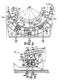
- Fig. 1 a partial transverse sectional view of a dynamoelectric machine 10, such as a turbine generator, having a casing structure 12 which houses a laminated stator core 14 and a rotatable rotor 16.
- the stator core 14, as is conventional, is a cylindrical structure disposed about an axis 18 which is coincidental with the axis of rotation of the rotor 16.
- the stator winding 22 includes a plurality of interconnected coils 24 which are formed by electrically connecting a suitable number of half coils or coil sides 26 and 28 which are respectively disposed in different axial slots 20 and are connected in the axial end regions of the dynamoelectric machine 10.
- Coil sides 26 and 28 are respectively disposed in the radially inner and radially outer portions of different axial slots 20.
- stator winding 22 illustrated in the figures has two coil sides disposed in each axial slot, it is to be understood that any number of coil sides may be disposed in each axially extending slot with each of those coil sides being interconnectable with coil sides disposed in other slots which are circumferentially displaced therefrom.
- Each stator coil includes two coil terminating sides 26a and 28a respectively disposed in a radially inner or top portion of a slot and the radially outer or bottom portion of the slot.
- the ends of coil sides 26a and 28a respectively constitute electrical phase terminals 26b and 28b which are respectively disposed at radial distances A and B from the axis 18.
- a set of parallel conducting ring structures 30 are circumferentially disposed about stator core 14 at one axial end 31 thereof.
- the six illustrated conducting ring structures 30, respectively, include parallel conducting rings 30a, 30b, 30C, 30d, 30e, and 30f which are each electrically connected to a separate phase terminal 26b and 28b by phase leads 32a and 32b, respectively.
- each of the conducting rings 30a through 30f are electrically connected to main leads 34a, 34b, 34c, 34d, 34e, and 34f in order to conduct the current generated by the dynamoelectric machine 10 externally therefrom.
- the number of axially adjacent parallel conducting rings actually varies in the circumferential direction according to the number of phases, the series or parallel character of the stator winding, and the split or full character of the phase zones of the stator winding.
- a four-pole, three phase dynamoelectric machine 10 is shown for the illustrated embodiment.
- Such rotations in combination with a counter-clockwise rotation of the rotor 16 are typically provided for, respectively, by a "standard” parallel ring connection or by an “opposite” parallel ring connection as explained herein above.
- stator core 14 is of usual laminated construction.
- the stator winding coils 24 are of the liquid cooled type and comprise hollow conductors having internal passageways which open to coolant headers (not shown) which manifold coolant through the internal passageways.
- the diameter of the conductors themselves is chosen to accommodate an amperage rating of approximately 36,000 amperes.
- the conductors of the parallel conducting rings are conventionally formed of copper pipe having an outside diameter of approximately 4.45 cm (1.75 in.) and an inside diameter of approximately 1.91 cm (0.75 in.).
- the full phase or "double" current rings are also formed of copper pipe having an outside diameter of approximately 6.99 cm (2.75 in.) and an inside diameter of approximately 2.54 cm (1.00 in.). Both types of copper pipes are further insulated (to a rating of approximately 26 kilovolts) by covering same with an insulative material, such as glass-backed mica paper, of approximately 0.97 cm (0.38 in.) thickness.
- an insulative material such as glass-backed mica paper
- the conducting rings 30a through 30f are arranged as shown in the developed view of Fig. 6. Referring for the moment to that figure, in conjunction with Figs. 1-5, it can be seen that the conducting rings 30a through 30f are arranged parallel one to the other in six banks ("bank 1" hereinafter referring to the bank which is closest to the stator core 14 and "bank 6 ⁇ referring to the bank which is farthest away from the stator core 14).
- the conducting ring 30f situated in bank 1 is positioned relative to the stator core 14 such that a strike distance for approximately 26 kilovolts is maintained.
- the conducting rings 30a through 30f are mounted upon a cleat 36 having a plurality of cylindrically shaped channels 38 formed therein.
- the cleat 36 having the conducting rings 30a through 30f thusly situated within its channels 38 is mounted to conventional means for supporting the stator winding 22 at its terminating ends 26a, 26b, 28a, and 28b, such as a support cone 40 which is mounted to the stator core 14.
- a spacer 42 is also utilized in accordance with the present invention between the conducting rings 30a through 30d and the support cone 40 to accommodate for variations in the bended radius of the conducting rings 30a through 30d, thereby firmly mounting such rings to the support cone 40 to prevent undesirable mechanical vibrations.
- the cleats 36 are suitably mounted to the support cone 40 by bolt means 44 such as a plurality of non-conductive bolts.
- the bolt means 44 is formed of threaded studs 46, such as fiberglass studs, which are attached to nuts 48 of a similar material.
- their threaded studs 46 are coated with a suitable lubricant, such as paraffin.
- at least two belleville washers 50 are coupled to the threaded studs 46 just beneath te cleat 36 , formed of a non-conductive material such as fiberglass, which provide for a tight connection in spite of mechanical vibrations.
- such conducting ring 30b is situated within the channel 38 comprising bank 5.
- This arrangement minimizes the effects of mechanical vibrations upon the phase leads 32a and 32b by positioning the conducting ring 30b as close as possible to the terminating sides 26a, 26b, 28a, and 28b.
- the conducting ring 30a is situated within the channel 38 comprising bank 6 in order to facilitate a subassembly of the conducting rings 30a through 30f and the support cone 40 which is suitable for both standard and opposite parallel ring connections.
- the conducting rings 30a and 30b contained in the channels 38 comprising, respectively, banks 6 and 5 are clamped between the cleat 36 and a member 52 which also includes cylindrically shaped channels 38.
- Bolt means 44 similar in all respects to the bolt means 44 used to attach the cleat 36 to the support cone 40, are also used to attach the member 52 to the cleat 36.
- Each of the bolt means 44 are suitably locked in place by pin means (not shown).
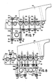
- the full phase or "double" current rings 30g, 30h, and 30i which are used to conduct the current generated by the dynamoelectric machine 10 to the main leads 34a, 34e, and 34f (comprising, respectively, T1, T5, and T6) will now be explained.
- connection to the main lead 34a i.e., T1 is provided in accordance with the present invention by the full phase ring 30g which is situated beneath bank 5 along an arc extending from approximately 32° to approximately 82 o .
- Such full phase ring 30g is clamped between a two-part member 54a and 54b which is attached to the cleat 36 by bolt means 44 as shown in Fig. 7.
- the bolt means 44 used to attach the two-part member 54a and 54b to the cleat 36 must be independent of the bolt means 44 used to secure the clamping member 52 in order to avoid problems associated with creep shrinkage.
- connection to the main lead 34e i.e., T5
- connection to the main lead 34e i.e., T5
- connection to the main lead 34f i.e., T6
- connection to the main lead 34f is provided by the full phase ring 30i which is also situated beneath bank 2 along an arc extending from approximately 268° to approximately 328°.
- the full phase rings 30h and 30i are also secured to the cleat 36 by a two-part member 54a and 54b clamped together by bolt means 44 as shown in Fig. 8.
- the conducting rings 30a through 30i include a plurality of tab means 56a and 56b which are used to conduct the current generated by the dynamoelectric machine 10 from the conducting rings 30a through 30i out through the main leads 34a through 34f.
- Figs. 9 and 10 illustrate the tab means 56a which are used to connect the main leads 34a through 34f to their respective conducting rings, while the tab means 56b used to connect at full phase or "double" current joints is illustrated in Figs. 11 and 12.
- the tab means 56a are suitably formed in accordance with the present invention of a conductive member 58 which includes means for circulating the fluid coolant therethrough (such as a coolant path 60 formed in the conductive member 58) and a tab portion 62 having a plurality of connector holes 64 formed therein in order to connect the tab means 56a to a flexible connector portion 66 of the main leads 34a through 34f.
- a conductive member 58 which includes means for circulating the fluid coolant therethrough (such as a coolant path 60 formed in the conductive member 58) and a tab portion 62 having a plurality of connector holes 64 formed therein in order to connect the tab means 56a to a flexible connector portion 66 of the main leads 34a through 34f.
- the flexible connector portions 66 are suitably formed of individual conductive members (not shown) which are covered with a braided material 68, and which have their end portions 66a and 66b stamped flat to form a portion which has two holes drilled therethrough for mating with respective connector holes 64 formed in the tab means 56a.
- the particular number of sub-leads which are utilized in the flexible connector portions 66 of the main leads 34a through 34f is merely a function of the amount of current which the conductive members are designed to carry. Therefore, the number of sub-leads, as well as the number of connector holes 64, may vary without departing from the teachings of the present invention.
- the tab means 56b are formed as shown in Figs. 11 and 12.
- the tab means 56b include a conductive member 70 with means for circulating the fluid coolant therethrough (such as a coolant path 72 formed in the conductive member 70) and a tab portion 74 having a plurality of connector holes 76 formed therein for a tab-to-tab connection between the conducting rings.
- the tab portion 74 of the tab means 56b are split into three sub-portions in order to provide a more reliable, but flexible contact pressure. All connections at the tab means 56a and 56b (through the connector holes 64 and 76) are provided for by any suitable conductive bolt means (not shown).
- the tab means 56a and 56b are effectively connected to the conducting rings by any suitable means such as by brazing.
- tab means 56a and 56b are provided for at locations as shown in the developed view of Fig. 6.
- Such tab means 56a and 56b are fully insulated with a suitable groundwall insulation, such as Thermalastic (a registered trademark of Westinghouse Electric Corporation), which permits the insulated metal of the tab means 56a and 56b to expand and contract without breakage of the insulation.
- the main leads 34a and 34d are both connected at approximately 32° (Fig. 6).
- T1 regardless of the particular configuration of the machine 10, the full phase or "double" current ring 30g is connected to the conducting ring 30b at 82° utilizing a tab-to-tab connection with tab means 56b. Thereafter, the full phase or "double” current ring 30g is routed beneath bank 5 where it is terminated at approximately 32° with tab means 56a for connection with the flexible connector portion 66 attached to main lead 34a.
- connection for T4 is provided by tab means 56a attached to the conducting ring 30e (i.e., bank 2) at 32°.
- connection of the remaining main leads 34b, 34c, 34e, and 34f will now be explained for a standard parallel ring connection.
- the connection for main lead 34b (corresponding to T2) is made utilizing tab means 56a attached to the conducting ring 3°C at approximately 3°, while the connections for main leads 34c and 34f (corresponding respectively to T3 and T6) are made utilizing tab means 56a attached to the conducting rings 30c and 30e at approximately 328°.
- One end of the full phase or "double" current ring 30h is provided with a tab-to tab connection to the conducting ring 30c, utilizing tab means 56b, at approximately 268°, while the connection for main lead 34e (corresponding to T5) is made utilizing tab means 56a attached to the other end of the full phase or "double” current ring 30h, located beneath bank 2, at approximately 3°.
- Tab means 56a attached to the conducting rings 30a and 30e at approximately 3°, remain insulated as described herein above and are unused for dynamoelectric machines 10 utilizing a standard parallel ring connection.
- connection of the remaining main leads 34b, 34c, 34e, and 34f will now be explained for an opposite parallel ring connection.
- the connection of the main lead 34b (corresponding to T2) is made utilizing tab means 56a attached to the conducting ring 30a at approximately 3°, while the connections for main leads 34c and 34e (corresponding respectively to T3 and T5) are made utilizing tab means 56a attached to the conducting rings 30a and 30a located, respectively, at 328 o and 3 o .
- One end of the full phase or "double" current ring 30i is provided with a tab-to-tab connection to the conducting ring 30c, utilizing tab means 56b, at approximately 268 o , while the connection for main lead 34f (corresponding to T6) is made utilizing tab means 56a attached to the other end of the full phase or "double" current ring 30i, located beneath bank 2, at approximately 328 o .
- Tab means 56a attached to the conducting rings 30c and 30e at approximately 328 o , remain insulated as described herein above and are unused for dynamoelectric machines 10 utilizing an opposite parallel ring connection.
Applications Claiming Priority (2)
| Application Number | Priority Date | Filing Date | Title |
|---|---|---|---|
| US07/288,369 US4943749A (en) | 1988-12-22 | 1988-12-22 | Method and apparatus for conducting current from a dynamoelectric machine |
| US288369 | 1999-04-08 |
Publications (3)
| Publication Number | Publication Date |
|---|---|
| EP0375419A2 true EP0375419A2 (de) | 1990-06-27 |
| EP0375419A3 EP0375419A3 (de) | 1991-08-14 |
| EP0375419B1 EP0375419B1 (de) | 1994-11-02 |
Family
ID=23106809
Family Applications (1)
| Application Number | Title | Priority Date | Filing Date |
|---|---|---|---|
| EP89313431A Expired - Lifetime EP0375419B1 (de) | 1988-12-22 | 1989-12-21 | Dynamoelektrische Maschine |
Country Status (8)
| Country | Link |
|---|---|
| US (1) | US4943749A (de) |
| EP (1) | EP0375419B1 (de) |
| JP (1) | JP2750763B2 (de) |
| KR (1) | KR900011102A (de) |
| CN (1) | CN1044366A (de) |
| CA (1) | CA2006285A1 (de) |
| ES (1) | ES2063832T3 (de) |
| YU (1) | YU240489A (de) |
Cited By (6)
| Publication number | Priority date | Publication date | Assignee | Title |
|---|---|---|---|---|
| EP1811634A1 (de) * | 2006-01-24 | 2007-07-25 | ALSTOM Technology Ltd | Verbindungsanordnung für die Statorwicklung einer Turbomaschine mit 2 oder mehr parallelen Kreisen |
| EP1879279A1 (de) * | 2006-07-14 | 2008-01-16 | Ansaldo Energia S.P.A. | Stator eines Turbogenerators |
| CN101888127A (zh) * | 2009-05-13 | 2010-11-17 | 阿尔斯通技术有限公司 | 用于电机的端部绕组及其制造方法 |
| WO2020079408A1 (en) * | 2018-10-16 | 2020-04-23 | Cummins Generator Technologies Limited | Stator winding arrangement |
| EP3661024A1 (de) * | 2018-11-28 | 2020-06-03 | Siemens Gamesa Renewable Energy A/S | Stator für eine elektrische maschine, windturbine und verfahren zur herstellung eines stators |
| WO2021204437A1 (de) * | 2020-04-06 | 2021-10-14 | Flender Gmbh | Haltesystem für stromschienen an statoren bzw. statorsegmenten dynamoelektrischer maschinen |
Families Citing this family (11)
| Publication number | Priority date | Publication date | Assignee | Title |
|---|---|---|---|---|
| US5355046A (en) * | 1989-12-15 | 1994-10-11 | Klaus Weigelt | Stator end-winding system and a retrofitting set for same |
| US5789840A (en) * | 1996-02-29 | 1998-08-04 | Ge Canada Inc. | Endhead joint for stator bars |
| US6157109A (en) * | 1998-02-10 | 2000-12-05 | Reliance Electric Technologies, Llc | Dynamoelectric machine with ferromagnetic end winding ring |
| FR2775426B1 (fr) | 1998-03-02 | 2000-05-19 | Delsey Soc | Valise a roulettes a station debout |
| US6538339B2 (en) | 2000-03-02 | 2003-03-25 | Siemens Westinghouse Power Corporation | Power generation system interchangeability device and related methods |
| JP4913538B2 (ja) * | 2006-10-23 | 2012-04-11 | 古河電気工業株式会社 | 集中配電部品 |
| CN100568670C (zh) * | 2007-03-28 | 2009-12-09 | 上海电气集团上海电机厂有限公司 | 大功率变频交流电机定子端部连接导电环的结构及方法 |
| US8084914B2 (en) * | 2009-01-26 | 2011-12-27 | Schlumberger Technology Corporation | Stator coil retention system for unvarnished stators |
| US20110018483A1 (en) * | 2009-07-21 | 2011-01-27 | General Electric Company | Stator end-winding component monitoring system |
| US8461742B2 (en) * | 2010-11-19 | 2013-06-11 | General Electric Company | Support system for dynamoelectric machine |
| EP2571145B1 (de) * | 2011-09-13 | 2017-08-02 | General Electric Technology GmbH | Verbindungsanordnung für Wicklungen von elektrischen Maschinen |
Citations (7)
| Publication number | Priority date | Publication date | Assignee | Title |
|---|---|---|---|---|
| GB1127916A (en) * | 1965-10-08 | 1968-09-18 | Parsons C A & Co Ltd | Improvements in and relating to dynamo-electric machines |
| DE2161139A1 (de) * | 1971-12-09 | 1973-06-14 | Bbc Brown Boveri & Cie | Elastische wickelkopfabstuetzung fuer grosse elektrische maschine |
| FR2191325A1 (de) * | 1972-06-26 | 1974-02-01 | Kraftwerk Union Ag | |
| EP0015429A1 (de) * | 1979-02-28 | 1980-09-17 | Westinghouse Electric Corporation | Abstützung für parallele Sammelringe und Abzweigleiter der Sammelringe für dynamoelektrische Maschinen |
| US4488072A (en) * | 1983-06-08 | 1984-12-11 | General Electric Company | Generator stator frame with integral high-voltage bushings |
| US4501985A (en) * | 1984-05-01 | 1985-02-26 | Westinghouse Electric Corp. | Dynamoelectric machine with end turn support assembly having fasteners with locking devices |
| EP0213863A2 (de) * | 1985-08-27 | 1987-03-11 | The Superior Electric Company | Programmierbarer elektrischer Steckverbinder |
Family Cites Families (3)
| Publication number | Priority date | Publication date | Assignee | Title |
|---|---|---|---|---|
| US905889A (en) * | 1905-06-28 | 1908-12-08 | Westinghouse Electric & Mfg Co | Coil-support for dynamo-electric machinery. |
| US4199700A (en) * | 1978-07-31 | 1980-04-22 | Westinghouse Electric Corp. | Phase lead for connecting stator coils and parallel phase rings |
| US4314173A (en) * | 1980-04-10 | 1982-02-02 | Westinghouse Electric Corp. | Mounting bracket for bracing peripheral connecting rings for dynamoelectric machines' stator windings |
-
1988
- 1988-12-22 US US07/288,369 patent/US4943749A/en not_active Expired - Lifetime
-
1989
- 1989-12-19 YU YU240489A patent/YU240489A/sh unknown
- 1989-12-21 ES ES89313431T patent/ES2063832T3/es not_active Expired - Lifetime
- 1989-12-21 JP JP1332514A patent/JP2750763B2/ja not_active Expired - Lifetime
- 1989-12-21 EP EP89313431A patent/EP0375419B1/de not_active Expired - Lifetime
- 1989-12-21 CA CA002006285A patent/CA2006285A1/en not_active Abandoned
- 1989-12-22 CN CN89109451A patent/CN1044366A/zh active Pending
- 1989-12-22 KR KR1019890019331A patent/KR900011102A/ko not_active Application Discontinuation
Patent Citations (7)
| Publication number | Priority date | Publication date | Assignee | Title |
|---|---|---|---|---|
| GB1127916A (en) * | 1965-10-08 | 1968-09-18 | Parsons C A & Co Ltd | Improvements in and relating to dynamo-electric machines |
| DE2161139A1 (de) * | 1971-12-09 | 1973-06-14 | Bbc Brown Boveri & Cie | Elastische wickelkopfabstuetzung fuer grosse elektrische maschine |
| FR2191325A1 (de) * | 1972-06-26 | 1974-02-01 | Kraftwerk Union Ag | |
| EP0015429A1 (de) * | 1979-02-28 | 1980-09-17 | Westinghouse Electric Corporation | Abstützung für parallele Sammelringe und Abzweigleiter der Sammelringe für dynamoelektrische Maschinen |
| US4488072A (en) * | 1983-06-08 | 1984-12-11 | General Electric Company | Generator stator frame with integral high-voltage bushings |
| US4501985A (en) * | 1984-05-01 | 1985-02-26 | Westinghouse Electric Corp. | Dynamoelectric machine with end turn support assembly having fasteners with locking devices |
| EP0213863A2 (de) * | 1985-08-27 | 1987-03-11 | The Superior Electric Company | Programmierbarer elektrischer Steckverbinder |
Cited By (15)
| Publication number | Priority date | Publication date | Assignee | Title |
|---|---|---|---|---|
| US7489058B2 (en) | 2006-01-24 | 2009-02-10 | Alstom Technology Ltd. | Connection arrangement for the stator winding of a turbo machine having two or more parallel circuits |
| EP1811634A1 (de) * | 2006-01-24 | 2007-07-25 | ALSTOM Technology Ltd | Verbindungsanordnung für die Statorwicklung einer Turbomaschine mit 2 oder mehr parallelen Kreisen |
| EP2365611A1 (de) * | 2006-07-14 | 2011-09-14 | Ansaldo Energia S.p.A. | Stator eines Turbogenerators |
| WO2008006913A3 (en) * | 2006-07-14 | 2008-03-27 | Ansaldo Energia Spa | Stator of a turbo generator |
| WO2008006913A2 (en) * | 2006-07-14 | 2008-01-17 | Ansaldo Energia S.P.A. | Stator of a turbo generator |
| EP1879279A1 (de) * | 2006-07-14 | 2008-01-16 | Ansaldo Energia S.P.A. | Stator eines Turbogenerators |
| US8072102B2 (en) | 2006-07-14 | 2011-12-06 | Ansaldo Energia S.P.A. | Stator of a turbo generator |
| CN101501960B (zh) * | 2006-07-14 | 2012-02-22 | 安萨尔多能源公司 | 涡轮发电机的定子 |
| CN101888127A (zh) * | 2009-05-13 | 2010-11-17 | 阿尔斯通技术有限公司 | 用于电机的端部绕组及其制造方法 |
| EP2251960A3 (de) * | 2009-05-13 | 2014-06-18 | Alstom Technology Ltd | Wickelkopf für eine elektrische Maschine und Verfahren zu dessen Herstellung |
| CN101888127B (zh) * | 2009-05-13 | 2015-07-22 | 阿尔斯通技术有限公司 | 用于电机的端部绕组及其制造方法 |
| WO2020079408A1 (en) * | 2018-10-16 | 2020-04-23 | Cummins Generator Technologies Limited | Stator winding arrangement |
| EP3661024A1 (de) * | 2018-11-28 | 2020-06-03 | Siemens Gamesa Renewable Energy A/S | Stator für eine elektrische maschine, windturbine und verfahren zur herstellung eines stators |
| WO2020108809A1 (en) * | 2018-11-28 | 2020-06-04 | Siemens Gamesa Renewable Energy A/S | Stator for an electrical machine, wind turbine and method for manufacturing a stator |
| WO2021204437A1 (de) * | 2020-04-06 | 2021-10-14 | Flender Gmbh | Haltesystem für stromschienen an statoren bzw. statorsegmenten dynamoelektrischer maschinen |
Also Published As
| Publication number | Publication date |
|---|---|
| CA2006285A1 (en) | 1990-06-22 |
| KR900011102A (ko) | 1990-07-11 |
| EP0375419A3 (de) | 1991-08-14 |
| ES2063832T3 (es) | 1995-01-16 |
| YU240489A (sh) | 1992-09-07 |
| JP2750763B2 (ja) | 1998-05-13 |
| CN1044366A (zh) | 1990-08-01 |
| EP0375419B1 (de) | 1994-11-02 |
| US4943749A (en) | 1990-07-24 |
| JPH033628A (ja) | 1991-01-09 |
Similar Documents
| Publication | Publication Date | Title |
|---|---|---|
| US4943749A (en) | Method and apparatus for conducting current from a dynamoelectric machine | |
| US6791227B2 (en) | Dynamo electric machine and method of manufacturing the same | |
| US4481438A (en) | High voltage electrical generator and windings for use therein | |
| US10476336B2 (en) | Stator assembly | |
| EP2369722A2 (de) | Stator für eine elektrische Maschine | |
| US5196752A (en) | System for supporting conductors for use in a dynamoelectric machine | |
| US10951084B2 (en) | Power distribution for rotary electric machine | |
| JP2001211591A (ja) | 半径方向に挿入されたケーブル巻線を有する高電圧発電機固定子及びその組立て方法 | |
| US20200227969A1 (en) | Stator windings for an electric motor or generator | |
| JPH09247881A (ja) | 電動機の固定子 | |
| US7948127B2 (en) | Connection method for rotating rectifiers on a generator | |
| US4151433A (en) | Cooled spiral winding for electrical rotating machine stator | |
| US20230344323A1 (en) | Mechanical strength of connection of wound rotor generator/motor | |
| US4268772A (en) | Laminated rotor with cast end windings | |
| JP2006187164A (ja) | 回転電機 | |
| US11626766B2 (en) | Power connection with overmolded axially adjusted connecting rings | |
| US4336474A (en) | Phase interleaved peripheral connector ring end winding | |
| EP2095489B1 (de) | Rotorpolquerverbindung einschliesslich querfugen | |
| US11532964B2 (en) | Generator rotor flat wire winding | |
| US20040061390A1 (en) | Apparatus and method for connecting parallel stator windings | |
| EP2133979A1 (de) | Vielphasengeneratoranordnung | |
| US10840015B2 (en) | Laminated core rotatable transformer | |
| EP4287466A1 (de) | Verbindungswicklungen der statorbaugruppe | |
| EP0154630B1 (de) | Kompaktwiderstandseinheit für elektrische drehmaschinen | |
| EP0615333B1 (de) | Verbindungselement für Wicklungen in rotierenden elektrischen Bauteilen |
Legal Events
| Date | Code | Title | Description |
|---|---|---|---|
| PUAI | Public reference made under article 153(3) epc to a published international application that has entered the european phase |
Free format text: ORIGINAL CODE: 0009012 |
|
| AK | Designated contracting states |
Kind code of ref document: A2 Designated state(s): BE ES FR IT |
|
| PUAL | Search report despatched |
Free format text: ORIGINAL CODE: 0009013 |
|
| AK | Designated contracting states |
Kind code of ref document: A3 Designated state(s): BE ES FR IT |
|
| 17P | Request for examination filed |
Effective date: 19910910 |
|
| 17Q | First examination report despatched |
Effective date: 19930115 |
|
| GRAA | (expected) grant |
Free format text: ORIGINAL CODE: 0009210 |
|
| AK | Designated contracting states |
Kind code of ref document: B1 Designated state(s): BE ES FR IT |
|
| ET | Fr: translation filed | ||
| PGFP | Annual fee paid to national office [announced via postgrant information from national office to epo] |
Ref country code: BE Payment date: 19950106 Year of fee payment: 6 |
|
| REG | Reference to a national code |
Ref country code: ES Ref legal event code: FG2A Ref document number: 2063832 Country of ref document: ES Kind code of ref document: T3 |
|
| ITF | It: translation for a ep patent filed |
Owner name: MODIANO & ASSOCIATI S.R.L. |
|
| PLBE | No opposition filed within time limit |
Free format text: ORIGINAL CODE: 0009261 |
|
| STAA | Information on the status of an ep patent application or granted ep patent |
Free format text: STATUS: NO OPPOSITION FILED WITHIN TIME LIMIT |
|
| 26N | No opposition filed | ||
| PG25 | Lapsed in a contracting state [announced via postgrant information from national office to epo] |
Ref country code: BE Effective date: 19951231 |
|
| BERE | Be: lapsed |
Owner name: WESTINGHOUSE ELECTRIC CORP. Effective date: 19951231 |
|
| PGFP | Annual fee paid to national office [announced via postgrant information from national office to epo] |
Ref country code: ES Payment date: 19991229 Year of fee payment: 11 |
|
| PG25 | Lapsed in a contracting state [announced via postgrant information from national office to epo] |
Ref country code: ES Free format text: LAPSE BECAUSE OF NON-PAYMENT OF DUE FEES Effective date: 20011222 |
|
| REG | Reference to a national code |
Ref country code: ES Ref legal event code: FD2A Effective date: 20020112 |
|
| PG25 | Lapsed in a contracting state [announced via postgrant information from national office to epo] |
Ref country code: IT Free format text: LAPSE BECAUSE OF NON-PAYMENT OF DUE FEES;WARNING: LAPSES OF ITALIAN PATENTS WITH EFFECTIVE DATE BEFORE 2007 MAY HAVE OCCURRED AT ANY TIME BEFORE 2007. THE CORRECT EFFECTIVE DATE MAY BE DIFFERENT FROM THE ONE RECORDED. Effective date: 20051221 |
|
| PGFP | Annual fee paid to national office [announced via postgrant information from national office to epo] |
Ref country code: FR Payment date: 20081219 Year of fee payment: 20 |