EP0375343A2 - Chariot à air stérile - Google Patents
Chariot à air stérile Download PDFInfo
- Publication number
- EP0375343A2 EP0375343A2 EP89313253A EP89313253A EP0375343A2 EP 0375343 A2 EP0375343 A2 EP 0375343A2 EP 89313253 A EP89313253 A EP 89313253A EP 89313253 A EP89313253 A EP 89313253A EP 0375343 A2 EP0375343 A2 EP 0375343A2
- Authority
- EP
- European Patent Office
- Prior art keywords
- air
- trolley
- top section
- working surface
- sterile
- Prior art date
- Legal status (The legal status is an assumption and is not a legal conclusion. Google has not performed a legal analysis and makes no representation as to the accuracy of the status listed.)
- Withdrawn
Links
Images

Classifications
-
- F—MECHANICAL ENGINEERING; LIGHTING; HEATING; WEAPONS; BLASTING
- F24—HEATING; RANGES; VENTILATING
- F24F—AIR-CONDITIONING; AIR-HUMIDIFICATION; VENTILATION; USE OF AIR CURRENTS FOR SCREENING
- F24F3/00—Air-conditioning systems in which conditioned primary air is supplied from one or more central stations to distributing units in the rooms or spaces where it may receive secondary treatment; Apparatus specially designed for such systems
- F24F3/12—Air-conditioning systems in which conditioned primary air is supplied from one or more central stations to distributing units in the rooms or spaces where it may receive secondary treatment; Apparatus specially designed for such systems characterised by the treatment of the air otherwise than by heating and cooling
- F24F3/16—Air-conditioning systems in which conditioned primary air is supplied from one or more central stations to distributing units in the rooms or spaces where it may receive secondary treatment; Apparatus specially designed for such systems characterised by the treatment of the air otherwise than by heating and cooling by purification, e.g. by filtering; by sterilisation; by ozonisation
- F24F3/163—Clean air work stations, i.e. selected areas within a space which filtered air is passed
-
- Y—GENERAL TAGGING OF NEW TECHNOLOGICAL DEVELOPMENTS; GENERAL TAGGING OF CROSS-SECTIONAL TECHNOLOGIES SPANNING OVER SEVERAL SECTIONS OF THE IPC; TECHNICAL SUBJECTS COVERED BY FORMER USPC CROSS-REFERENCE ART COLLECTIONS [XRACs] AND DIGESTS
- Y02—TECHNOLOGIES OR APPLICATIONS FOR MITIGATION OR ADAPTATION AGAINST CLIMATE CHANGE
- Y02A—TECHNOLOGIES FOR ADAPTATION TO CLIMATE CHANGE
- Y02A50/00—TECHNOLOGIES FOR ADAPTATION TO CLIMATE CHANGE in human health protection, e.g. against extreme weather
- Y02A50/20—Air quality improvement or preservation, e.g. vehicle emission control or emission reduction by using catalytic converters
Definitions
- This invention relates to a sterile air trolley for provision of a sterile air zone, including a work surface, free from airborne microbial or particulate contaminents.
- Such a trolley which comprises a mobile casing, is particularly useful in surgical operating theatres to provide, at any desired location, a sterile surface on which surgical instruments and associated items can be unwrapped and laid. Additionally, by suitable positioning, such a trolley can function to minimise, indeed substantially prevent, airborne contamination of the operating site (wound) as well as gloved hands, gowns, drapes etc. which are introduced into the area of the operating site. Of course, other applications of such a trolley are possible, for example in providing a local sterile area for purposes of pharmaceutical or electronic production steps where a full clean room environment is not available or needs to be supplemented.
- a sterile air trolley has been previously proposed in UK patent specification No. 2108846. In that proposal an upper region of the trolley extended laterally beyond the lower region and outlets for sterile air were distributed throughout that upper region, including the upper surface thereof, which provided the sterile surface for placement of instruments.
- a sterile air trolley comprising a mobile casing providing a substantially horizontal working surface and having one or more inlets in its lower region and a plurality of air outlets in its upper region, and an impeller enclosed within the casing and operative to move air in through said inlet or inlets, through a filter, and out of the casing by way of the outlets
- the upper region of the casing is in the form of a top section having side walling which extends upwardly from said working surface, and in that the air outlets are distributed over at least a part of said top section side walling so that actuation of the impeller causes lateral air flow from said side walling to sweep across said working surface.
- the top section is in the form of a detachable fitment. This facilitates assembly, repair, cleaning and replacement.
- the air outlets are distributed throughout the top section side walling so as to prevent ambient air entrainment (i.e. peripheral inflow of surrounding air carrying contaminents to the zone intended to be kept sterile).
- the top section preferably also has air outlets disbrimped throughout its upper walling.
- a further measure, additional to or as an alternative to the foregoing, is to have one or more arcuate plates mounted inside the top section, each plate constituting a curved baffle which guides upflowing air outwardly in a direction across the working surface, preferably in a substantially horizontal direction.
- the plate or plates may have flanges at each side to enhance this directional effect, i.e. reduce air flow out at the sides.
- side panels may optionally be mounted on the working surface, extending from the top section walling. These panels act to some extent as baffles, serving to maintain the direction of air flow, and define the working area of greatest sterility. They also further reduce the risk of entry into that area of airborne contaminents from the surrounding air.
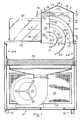
- this particular construction of trolley comprises a mobile casing in the form of a lower box - like housing 10 supported upon castors 12 and a detachable fitment 14 constituting a top section from which sterile air is discharged.
- the housing 10 has air inlets 16 located adjacent the lower edge of each of its four side walls and respective pre-filters 18 are mounted over these inlets 16 inside the housing 10. Also inside the housing 10 is an impeller in the form of a motor-driven fan 20 and, arranged across the housing, above the fan, a HEPA (high efficiency particulate air) filter 30. A silencer is also provided, but not illustrated.
- the castors 12 are located at the respective corners of the housing 10.
- the housing 10 has a substantially horizontal and continuous (imperforate) upper surface 22 which, upon operation of the trolley, constitutes a sterile working surface.
- the surface 22 does not extend the entire area between the top edges of the housing side walls and a large opening remains towards the rear, over which the top section fitment 14 is installed.
- the lower edge margin of the top section fitment 14 fits snugly into the opening, whilst an external ledge, provided by an encircling L-section strip 15 spaced a short distance above the lower edge, rests on the edge margins of the housing 10 which define said opening. Clips or bolts may additionally or alternatively be employed.
- the fitment 14 may fit over an upturned rim around the opening at the top of the housing 10.
- the top section 14 in the illustrated embodiment is a structure, defining a diffusion chamber 34, which is oblong in transverse cross-section, as shown in Fig. 2. Its precise shape is not critical and in alternative embodiments the top section could equally well be circular or rectangular. It has upper walling in the form of two symmetrical regions 24 sloping from a central ridge 26. Air outlets in the form of apertures which may be circular, oval or rectangular, or may be provided by wire mesh or woven fabric mounted on a framework, are distributed over the entire side walling and upper walling 24 of the fitment 14.
- the size of the apertures in the upper walling 24 is smaller than that of the apertures in the side walling, so air flow from the top of the fitment 14 will be lowest, as indicated by the arrows labelled L in Fig. 1.
- the apertures in the lower region of the wall section facing towards the surface 22 are of larger size than the remainder of apertures in the side walling so the velocity of air flow therefrom is higher, as indicated by the arrows labelled H in both Figs. 1 and 2.
- the remaining air flow is labelled M indicating an air flow velocity intermediate the aforesaid extremes issuing from the medium size apertures distributed over the remainder of the side walling.
- arcuate deflector plates 21, 23, 25 are mounted, as shown in all the drawings. These plates curve from the opening at the bottom of the fitment 14 towards the front walling, which faces the work surface 22.
- Two vertically disposed, perforated mounting plates 27, 29 are mounted onto the rear walls of the fitments 14 and extend towards, but end short of, the front wall.
- the arcuate plates 21, 23, 25 (which of course are imperforate) are mounted between these vertical plates 27, 29, by means of respective threaded shafts 31 which are welded to said plates 21, 23, 25, and by means of nuts 33.
- the positioning of the plates 21, 23, 25 can readily be changed as the shafts 31 can be inserted through any selected perforations in the mounting plates. Angular adjustment is also simply accomplished by loosening the nuts 33.
- the three plates 21, 23, 25 are disposed concentrically, one behind the other, i.e. the plates 23, 25 to the rear are of respectively greater radius.
- the plates 21, 23, 25 have flanges 41, 43, 45 which are directly inwardly with regard to the curvature of the plates (i.e. from their concave faces).
- the fan 20 When the fan 20 is actuated, air is drawn into the chamber inside the housing 10 through the prefilters 18 of the inlets 16, and after passing through the fan 20 itself the air is driven upwards through the filter 30, into the diffusion chamber 34 and out of the apertures of the top section 14.
- the arcuate plates 21, 23, 25 serve as baffles and direct a major proportion of the air towards and out of the front face of the fitment 14, and across the working surface 22 in a substantially horizontal pattern.
- the flanges 41, 43, 45 assist in reducing air flow out of the sides of the passageways between the plates 21, 23, 25.
- an air flow pattern is established as shown in the drawings, with the dominant flow, of highest velocity being directed across the work surface 22, on which surgical instruments can be placed to maintain their sterility.
- the sterile zone created by this dominant air flow will extend beyond the trolley such that if the trolley is appropriately positioned adjacent an operating site (wound) that also can be rendered aeromicrobiologically clean.
- This sterilising effect can be enhanced, i.e. the sterile air zone extended, by attaching a surgical drape (not shown) along the edge of the trolley work surface 22, opposite to the fitment 14, and stretching the drape out towards the operating site. The air flow will follow the surface of the drape (Coander effect) and the drape itself will prevent contaminated air flowing in from below.
- the additional air flow at low and medium velocities from the remainder of the top section 14 of the trolley is important in preventing entrainment or inflow of surrounding ambient contaminated air, which would otherwise reduce the extent of the sterile zone.
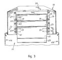
- respective side panels 36 may be fitted to the work surface 22. These panels 36 extend from the top section 14 to define and shield the sterile work zone where surgical instruments may be placed, or any operations requiring sterile conditions may be performed. In the illustrated example, the panels 36 diverge from the top section 14, but this is not essential.
- the panels 36 are preferably readily detachable, as is the fitment 14, and the internal baffle arrangement (plates 21, 23, 25, 27, 29). This facilitates cleaning, repair and replacement, as well as adjustment to ensure the best possible air flow pattern for the required extent and reliability of the sterile zone.
- the panels 36 may not always be required depending on the use to be made of the trolley, and the internal baffle arrangement is not essential, although it is preferred as it enhances the performance of the trolley.
- the work surface 22 may be perforated and the trolley base 10 may include lateral extensions, but such features are unnecessary and probably undesirable on grounds of cost, complexity and problems in maintenance.
- Additional air outlet apertures may, however, with considerable added advantage, be provided in the upper portions of the trolley side walls, above the level of the HEPA filter 30, as indicated by reference numerals 44 in Figs. 1 and 3. Outflow of air from these apertures 44 will prevent any entrainment of contaminents from below (i.e. any upflow of contaminated air from reaching the work surface 22). Moreover trays for holding instruments can usefully be hooked into some of these apertures 44 to obviate the need for any additional instrument trolleys, and these trays when so affixed will also, to a substantial extent, be within the sterile zone created by the trolley's own air flow pattern.
- the size of apertures 44 in the trolley side walls can also be appropriately graded, advantageously, largest at the top and smallest lower down.
- a sterile air trolley in accordance with the invention may be provided with two, three, four or more worksurfaces, arrayed around an upstanding perforated top section, or indeed a continuous worksurface encircling a top section, so as to have a considerably enlarged sterile air zone with minimum additional expenditure from a relatively compact piece of apparatus.
Landscapes
- Engineering & Computer Science (AREA)
- Chemical & Material Sciences (AREA)
- Combustion & Propulsion (AREA)
- Mechanical Engineering (AREA)
- General Engineering & Computer Science (AREA)
- Ventilation (AREA)
- Handcart (AREA)
- Air Filters, Heat-Exchange Apparatuses, And Housings Of Air-Conditioning Units (AREA)
- Disinfection, Sterilisation Or Deodorisation Of Air (AREA)
- Filtering Of Dispersed Particles In Gases (AREA)
Applications Claiming Priority (2)
| Application Number | Priority Date | Filing Date | Title |
|---|---|---|---|
| GB888829845A GB8829845D0 (en) | 1988-12-21 | 1988-12-21 | Sterile air trolley |
| GB8829845 | 1988-12-21 |
Publications (2)
| Publication Number | Publication Date |
|---|---|
| EP0375343A2 true EP0375343A2 (fr) | 1990-06-27 |
| EP0375343A3 EP0375343A3 (fr) | 1991-07-17 |
Family
ID=10648897
Family Applications (1)
| Application Number | Title | Priority Date | Filing Date |
|---|---|---|---|
| EP19890313253 Withdrawn EP0375343A3 (fr) | 1988-12-21 | 1989-12-19 | Chariot à air stérile |
Country Status (6)
| Country | Link |
|---|---|
| US (1) | US4996910A (fr) |
| EP (1) | EP0375343A3 (fr) |
| JP (1) | JPH02194807A (fr) |
| AU (1) | AU4679889A (fr) |
| GB (1) | GB8829845D0 (fr) |
| HU (1) | HUT56001A (fr) |
Cited By (2)
| Publication number | Priority date | Publication date | Assignee | Title |
|---|---|---|---|---|
| FR2750199A1 (fr) * | 1996-06-21 | 1997-12-26 | Cemagref Centre National Du Ma | Procede et dispositif de protection rapprochee d'un plan de travail au moyen d'un flux d'air propre |
| AT14037U1 (de) * | 2013-10-15 | 2015-03-15 | Umwelttech Ltd | Mobiles Luftreinigungsgerät |
Families Citing this family (7)
| Publication number | Priority date | Publication date | Assignee | Title |
|---|---|---|---|---|
| US5259812A (en) * | 1992-09-23 | 1993-11-09 | Kleinsek Don A | Clean room and clean room containment center |
| US6461233B1 (en) * | 2001-08-17 | 2002-10-08 | Labconco Corporation | Low air volume laboratory fume hood |
| GB2395110B (en) * | 2002-10-02 | 2005-08-10 | Silsoe Res Inst | Sterile air trolley |
| US7013902B2 (en) * | 2003-02-07 | 2006-03-21 | Applied Materials, Inc. | Wet cleaning mobile workbench |
| GB2457546B (en) * | 2008-02-25 | 2012-09-19 | A1 Envirosciences Ltd | Laboratory containment system |
| US9482439B2 (en) * | 2011-10-10 | 2016-11-01 | Salman Akhtar | Air handling device |
| CN207907312U (zh) * | 2018-01-31 | 2018-09-25 | 宁波方太厨具有限公司 | 一种吸油烟机的出风结构 |
Citations (4)
| Publication number | Priority date | Publication date | Assignee | Title |
|---|---|---|---|---|
| US3279883A (en) * | 1962-12-20 | 1966-10-18 | Midland Ross Corp | Distributing purified air |
| US3336855A (en) * | 1965-12-30 | 1967-08-22 | Atmos Tech Corp | Ultraclean work station |
| CA988357A (en) * | 1973-01-26 | 1976-05-04 | Her Majesty The Queen, In Right Of Canada, As Represented By The Minister Of National Defence | Back table clean station |
| DE2228419B2 (de) * | 1971-06-17 | 1981-03-19 | Pielkenrood-Vinitex B.V., Assendelft | Vorrichtung für die Zuleitung eines keimfreien Luftstromes über einen Operationstisch |
Family Cites Families (6)
| Publication number | Priority date | Publication date | Assignee | Title |
|---|---|---|---|---|
| GB778321A (en) * | 1955-02-24 | 1957-07-03 | British Ceramic Res Ass | Improvements in suction hoods |
| US3251177A (en) * | 1963-05-15 | 1966-05-17 | Arthur K Baker | Dust-free bench |
| US3426512A (en) * | 1967-06-28 | 1969-02-11 | Alexander G Nesher | Ventilation device for producing laminar flow |
| US3498032A (en) * | 1967-08-31 | 1970-03-03 | Moore & Hanks Co | High capacity low contamination bench |
| US4016809A (en) * | 1975-07-16 | 1977-04-12 | Contamination Control Laboratories, Inc. | Clean air workbench |
| EP0079122B1 (fr) * | 1981-11-10 | 1984-11-07 | Howorth Air Engineering Limited | Chariot de production d'air stérile |
-
1988
- 1988-12-21 GB GB888829845A patent/GB8829845D0/en active Pending
-
1989
- 1989-12-14 AU AU46798/89A patent/AU4679889A/en not_active Abandoned
- 1989-12-15 US US07/451,151 patent/US4996910A/en not_active Expired - Fee Related
- 1989-12-19 EP EP19890313253 patent/EP0375343A3/fr not_active Withdrawn
- 1989-12-20 JP JP1330949A patent/JPH02194807A/ja active Pending
- 1989-12-21 HU HU896725A patent/HUT56001A/hu unknown
Patent Citations (4)
| Publication number | Priority date | Publication date | Assignee | Title |
|---|---|---|---|---|
| US3279883A (en) * | 1962-12-20 | 1966-10-18 | Midland Ross Corp | Distributing purified air |
| US3336855A (en) * | 1965-12-30 | 1967-08-22 | Atmos Tech Corp | Ultraclean work station |
| DE2228419B2 (de) * | 1971-06-17 | 1981-03-19 | Pielkenrood-Vinitex B.V., Assendelft | Vorrichtung für die Zuleitung eines keimfreien Luftstromes über einen Operationstisch |
| CA988357A (en) * | 1973-01-26 | 1976-05-04 | Her Majesty The Queen, In Right Of Canada, As Represented By The Minister Of National Defence | Back table clean station |
Cited By (4)
| Publication number | Priority date | Publication date | Assignee | Title |
|---|---|---|---|---|
| FR2750199A1 (fr) * | 1996-06-21 | 1997-12-26 | Cemagref Centre National Du Ma | Procede et dispositif de protection rapprochee d'un plan de travail au moyen d'un flux d'air propre |
| WO1997049955A1 (fr) * | 1996-06-21 | 1997-12-31 | U.N.I.R. Ultra Propre-Nutrition Industrie-Recherche | Procede et dispositif de protection d'un plan de travail |
| US6095918A (en) * | 1996-06-21 | 2000-08-01 | N.I.R. Ultra Propre-Nutrition Industrie Recherche | Method and device for protecting a work surface |
| AT14037U1 (de) * | 2013-10-15 | 2015-03-15 | Umwelttech Ltd | Mobiles Luftreinigungsgerät |
Also Published As
| Publication number | Publication date |
|---|---|
| US4996910A (en) | 1991-03-05 |
| HU896725D0 (en) | 1990-03-28 |
| JPH02194807A (ja) | 1990-08-01 |
| GB8829845D0 (en) | 1989-02-15 |
| EP0375343A3 (fr) | 1991-07-17 |
| AU4679889A (en) | 1990-06-28 |
| HUT56001A (en) | 1991-07-29 |
Similar Documents
| Publication | Publication Date | Title |
|---|---|---|
| EP0528696B1 (fr) | Panneau de diffusion d'air directionnel pour système de ventilation des salles blanches | |
| US4560395A (en) | Compact blower and filter assemblies for use in clean air environments | |
| US7753977B2 (en) | Air filtration system having a removable diffuser | |
| US4996910A (en) | Sterile air trolley | |
| US10900665B2 (en) | Combination appliance having a cooktop and steam extraction device | |
| US5167681A (en) | Air filtration unit | |
| US6715484B2 (en) | Vent hood for a kitchen stove | |
| US4094232A (en) | Clean air zone | |
| FI71831B (fi) | Fraonluftsanordning | |
| US5318474A (en) | Radial flow diffuser | |
| CA1081027A (fr) | Appareil pour purifier l'ambiance d'une aire limitee | |
| US4521231A (en) | High capacity gas filter system | |
| US5220910A (en) | Device and method for ventilation | |
| CA1240874A (fr) | Panneau multi-etage repartiteur d'air pour hotte d'aeration | |
| US11859864B1 (en) | Particulate and virus barrier | |
| EP0372784B1 (fr) | Dispositif pour desservir une zone de salle blanche | |
| US6692346B2 (en) | Fume hood with alarm system | |
| US4137831A (en) | Clean air zone | |
| WO2003050453A1 (fr) | Station de travail dotee d'un dispositif de regulation du debit d'air | |
| CN208431868U (zh) | 空调器 | |
| JPH0767412B2 (ja) | 空調機能付テーブル | |
| CN108253541A (zh) | 空调器 | |
| EP1545367B1 (fr) | Chariot a air sterile | |
| CN207936451U (zh) | 空调室内机 | |
| CN219701410U (zh) | 过滤装置及过滤设备 |
Legal Events
| Date | Code | Title | Description |
|---|---|---|---|
| PUAI | Public reference made under article 153(3) epc to a published international application that has entered the european phase |
Free format text: ORIGINAL CODE: 0009012 |
|
| AK | Designated contracting states |
Kind code of ref document: A2 Designated state(s): AT BE CH DE ES FR GB GR IT LI LU NL SE |
|
| PUAL | Search report despatched |
Free format text: ORIGINAL CODE: 0009013 |
|
| RHK1 | Main classification (correction) |
Ipc: A61G 13/00 |
|
| AK | Designated contracting states |
Kind code of ref document: A3 Designated state(s): AT BE CH DE ES FR GB GR IT LI LU NL SE |
|
| STAA | Information on the status of an ep patent application or granted ep patent |
Free format text: STATUS: THE APPLICATION IS DEEMED TO BE WITHDRAWN |
|
| 18D | Application deemed to be withdrawn |
Effective date: 19920118 |