EP0374973A2 - Motor vehicle seat fitted with a seat belt - Google Patents
Motor vehicle seat fitted with a seat belt Download PDFInfo
- Publication number
- EP0374973A2 EP0374973A2 EP89124014A EP89124014A EP0374973A2 EP 0374973 A2 EP0374973 A2 EP 0374973A2 EP 89124014 A EP89124014 A EP 89124014A EP 89124014 A EP89124014 A EP 89124014A EP 0374973 A2 EP0374973 A2 EP 0374973A2
- Authority
- EP
- European Patent Office
- Prior art keywords
- seat
- belt
- connecting means
- secured
- relation
- Prior art date
- Legal status (The legal status is an assumption and is not a legal conclusion. Google has not performed a legal analysis and makes no representation as to the accuracy of the status listed.)
- Withdrawn
Links
Images


Classifications
-
- B—PERFORMING OPERATIONS; TRANSPORTING
- B60—VEHICLES IN GENERAL
- B60N—SEATS SPECIALLY ADAPTED FOR VEHICLES; VEHICLE PASSENGER ACCOMMODATION NOT OTHERWISE PROVIDED FOR
- B60N2/00—Seats specially adapted for vehicles; Arrangement or mounting of seats in vehicles
- B60N2/68—Seat frames
- B60N2/688—Particular seat belt attachment and guiding
-
- B—PERFORMING OPERATIONS; TRANSPORTING
- B60—VEHICLES IN GENERAL
- B60R—VEHICLES, VEHICLE FITTINGS, OR VEHICLE PARTS, NOT OTHERWISE PROVIDED FOR
- B60R22/00—Safety belts or body harnesses in vehicles
- B60R22/18—Anchoring devices
- B60R22/26—Anchoring devices secured to the seat
-
- B—PERFORMING OPERATIONS; TRANSPORTING
- B60—VEHICLES IN GENERAL
- B60R—VEHICLES, VEHICLE FITTINGS, OR VEHICLE PARTS, NOT OTHERWISE PROVIDED FOR
- B60R22/00—Safety belts or body harnesses in vehicles
- B60R22/18—Anchoring devices
- B60R2022/1818—Belt guides
Definitions
- the present invention relates to a motor vehicle seat fitted with a seat belt and designed to provide both maximum driving comfort and effective protection of the occupant in the event of collision.
- Known motor vehicle seat belts are connected, at one end, to a connecting member, usually a bracket, secured to the top of a pillar on the vehicle body, and, at the other end, to a second connecting member secured to the bottom of the pillar.
- Said second connecting member is usually provided with a winding member for automatically winding part of the seat belt when not in use.
- the seat belt itself in provided with a buckle connected to and sliding in relation to the belt, and which, when the belt is in use, is connected to a third connecting member secured to the central portion of the bodywork.
- belts of this type fail to provide for effective protection of the occupant in the event of collision, by virtue of said second portion of the belt over the upper torso presenting a substantially straightline configuration which does not provide for firmly restraining the uppermost part of the torso.
- assembly of the belt to vehicle body involves a good deal of time and effort, on account of the limited access available for fitting said connecting members as required to the body.
- the belt when not in use, the belt remains to the side of the seat, in such a position as to impede the freedom of movement of the occupant inside or when getting in and out of the passenger compartment.
- the aim of the present invention is to provide a motor vehicle seat fitted with a seat belt and designed to overcome the above drawbacks.
- a motor vehicle seat fitted with a seat belt and characterised by the fact that it comprises: an eyelet secured to the top of the seatback, on one side of the seat; first connecting means for securing a first end of said belt in a predetermined position in relation to the vehicle body; second connecting means for securing the second end of said belt in a predetermined position in relation to the vehicle body; said belt sliding through said eyelet and having a buckle connected to and sliding in relation to said belt, and designed, when said belt is in use, to engage third connecting means for securing said buckle in a predetermined position in relation to the vehicle body.
- the seat according to the present invention substantially comprises an eyelet 1 secured to the top 2 of seatback 3, on one side of the seat, as shown in
- first connecting means 4 for securing a first end 5 of belt 6 in a fixed position in relation to the vehicle body (not shown); and second connecting means 7 for also securing the second end 8 of belt 6 in a fixed position in relation to the vehicle body.
- Said belt 6 slides through eyelet 1, and presents a buckle 9 connected to and sliding in relation to belt 6, and designed, when belt 6 is in use, to engage in known manner with third connecting means 10 secured to the vehicle body.
- Said connecting means 4 are conveniently secured to one side of seat portion 13, and conveniently comprise an eyelet 14 to which the first end 5 of belt 6 is connected, and which is fitted by bracket 15 (Fig.3) to a plate 16 forming part of the seat supporting structure.
- Said second connecting means 7 are also conveniently secured to seat portion 13, to rear surface 17 of the same, and comprise a known winding device 18 for partially winding belt 6 automatically.
- winding device 18 is located on one side of surface 17, substantially in line with the same vertical plane as eyelet 1. Consequently, when in the idle position shown in Fig.1, belt 6 presents a first and second section 19 and 20 extending respectively over the front and rear surfaces of seatback 3.
- eyelet 1 conveniently comprises a plate 21 secured to seatback 3 and in which is formed a substantially rectangular opening 22 through which belt 6 slides.
- Said third connecting means substantially comprise a housing 23 secured by bracket 24 to a plate 25 forming part of the seat supporting structure, and having known engagement means for locking a suitable shaped plate 26 when this is inserted inside an opening in housing 23.
- the seat according to the present invention operates as follows.
- the seat is first assembled on to the vehicle body in the usual way, i.e. by fitting the seat supporting structure with a pair of rails 27 (Fig.s 3, 4) mating with a second pair of rails secured to the floor panel, for enabling the seat to slide longitudinally in relation to the vehicle body.
- Seatback 3 may be positioned in relation to seat portion 13 using any known type of device, and either may be designed in any appropriate manner for ensuring maximum comfort of the occupant.
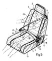
- Such a configuration provides for effectively safeguarding the occupant in the event of collision, by virtue of the restraining action of the belt at eyelet 1 being substantially parallel to the traveling direction of the vehicle and therefore perpendicular to plate 22 of eyelet 1, which provides for permanently securing the belt over the chest and shoulder of the occupant. Moreover, under normal driving conditions, maximum comfort of the occupant is assured by virtue of the upper portion of section 30 fitting substantially over the shoulder, as shown in Fig.5.
- the belt itself may be assembled quickly and easily to the seat before this is fitted to the vehicle body.
- the belt when in the idle position shown in Fig.1, the belt is retracted neatly so as to in no way impede the freedom of movement of the occupant inside or when getting in or out of the passenger compartment.
Abstract
Description
- The present invention relates to a motor vehicle seat fitted with a seat belt and designed to provide both maximum driving comfort and effective protection of the occupant in the event of collision.
- Known motor vehicle seat belts are connected, at one end, to a connecting member, usually a bracket, secured to the top of a pillar on the vehicle body, and, at the other end, to a second connecting member secured to the bottom of the pillar. Said second connecting member is usually provided with a winding member for automatically winding part of the seat belt when not in use. The seat belt itself in provided with a buckle connected to and sliding in relation to the belt, and which, when the belt is in use, is connected to a third connecting member secured to the central portion of the bodywork. When in use, therefore, a first portion of the belt extending substantially between said second and third connecting members fits substantially over the pelvic region of the occupant, whereas a second portion extending between said first and third connecting members fits over the upper torso.
- Known seat belts of the aforementioned type present a number of drawbacks.
- Firstly, in addition to being uncomfortable, belts of this type fail to provide for effective protection of the occupant in the event of collision, by virtue of said second portion of the belt over the upper torso presenting a substantially straightline configuration which does not provide for firmly restraining the uppermost part of the torso.
- Moreover, assembly of the belt to vehicle body involves a good deal of time and effort, on account of the limited access available for fitting said connecting members as required to the body.
- Finally, when not in use, the belt remains to the side of the seat, in such a position as to impede the freedom of movement of the occupant inside or when getting in and out of the passenger compartment.
- The aim of the present invention is to provide a motor vehicle seat fitted with a seat belt and designed to overcome the above drawbacks.
- With this aim in view, according to the present invention, there is provided a motor vehicle seat fitted with a seat belt and characterised by the fact that it comprises:
an eyelet secured to the top of the seatback, on one side of the seat;
first connecting means for securing a first end of said belt in a predetermined position in relation to the vehicle body;
second connecting means for securing the second end of said belt in a predetermined position in relation to the vehicle body;
said belt sliding through said eyelet and having a buckle connected to and sliding in relation to said belt, and designed, when said belt is in use, to engage third connecting means for securing said buckle in a predetermined position in relation to the vehicle body. - The invention will be described by way of example with reference to the accompanying drawings, in which:
- Fig.1 shows a front view in perspective of the seat according to the present invention, and with the seat belt in the rest position;
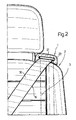
- Fig.2 shows a partial front view of the seatback on the seat according to the present invention;
- Fig.s 3 and 4 show partial opposite side views of the seat according to the present invention;
- Fig.5 shows a further front view in perspective of the seat according to the present invention, but with the seat belt in the operative position;
- Fig.6 shows a partial front view of the seat according to the present invention, with the seat portion omitted for the sake of simplicity.
- The seat according to the present invention substantially comprises an
eyelet 1 secured to thetop 2 ofseatback 3, on one side of the seat, as shown in - Fig.s 1, 2 and 5; first connecting means 4 for securing a
first end 5 ofbelt 6 in a fixed position in relation to the vehicle body (not shown); and second connecting means 7 for also securing thesecond end 8 ofbelt 6 in a fixed position in relation to the vehicle body. Saidbelt 6 slides througheyelet 1, and presents abuckle 9 connected to and sliding in relation tobelt 6, and designed, whenbelt 6 is in use, to engage in known manner with third connectingmeans 10 secured to the vehicle body. - Said connecting
means 4 are conveniently secured to one side ofseat portion 13, and conveniently comprise aneyelet 14 to which thefirst end 5 ofbelt 6 is connected, and which is fitted by bracket 15 (Fig.3) to aplate 16 forming part of the seat supporting structure. - Said second connecting means 7 are also conveniently secured to
seat portion 13, torear surface 17 of the same, and comprise a knownwinding device 18 for partially windingbelt 6 automatically. As shown clearly in Fig.1,winding device 18 is located on one side ofsurface 17, substantially in line with the same vertical plane aseyelet 1. Consequently, when in the idle position shown in Fig.1,belt 6 presents a first andsecond section seatback 3. - As shown clearly in Fig.2,
eyelet 1 conveniently comprises aplate 21 secured toseatback 3 and in which is formed a substantiallyrectangular opening 22 through which belt 6 slides. - Said third connecting means (Fig.4) substantially comprise a
housing 23 secured bybracket 24 to aplate 25 forming part of the seat supporting structure, and having known engagement means for locking a suitable shapedplate 26 when this is inserted inside an opening inhousing 23. - The seat according to the present invention operates as follows.
- The seat is first assembled on to the vehicle body in the usual way, i.e. by fitting the seat supporting structure with a pair of rails 27 (Fig.s 3, 4) mating with a second pair of rails secured to the floor panel, for enabling the seat to slide longitudinally in relation to the vehicle body.
Seatback 3 may be positioned in relation toseat portion 13 using any known type of device, and either may be designed in any appropriate manner for ensuring maximum comfort of the occupant. - When in the idle position shown in Fig.1, part of
belt 6 is wound insidewinding device 18 so as to pullsections seatback 3. Forsecuring belt 6 in the operative position, sufficient pull is exerted onbuckle 9 forreeling belt 6 offwinding device 18 and througheyelet 1, and soinserting plate 26 integral withbelt 9 insidehousing 23, as shown in Fig.s 4 and 5. This results in the formation of a belt section 28 (Fig.5) which fits substantially over the pelvic region ofoccupant 29, and asection 30 which fits over both the chest and shoulder. Such a configuration provides for effectively safeguarding the occupant in the event of collision, by virtue of the restraining action of the belt ateyelet 1 being substantially parallel to the traveling direction of the vehicle and therefore perpendicular toplate 22 ofeyelet 1, which provides for permanently securing the belt over the chest and shoulder of the occupant. Moreover, under normal driving conditions, maximum comfort of the occupant is assured by virtue of the upper portion ofsection 30 fitting substantially over the shoulder, as shown in Fig.5. The belt itself may be assembled quickly and easily to the seat before this is fitted to the vehicle body. - Moreover, when in the idle position shown in Fig.1, the belt is retracted neatly so as to in no way impede the freedom of movement of the occupant inside or when getting in or out of the passenger compartment.
- To those skilled in the art it will be clear that changes may be made to both the design and arrangement of the component parts of the seat as described and illustrated herein without, however, departing from the scope of the present invention.
Claims (8)
first connecting means (4) for securing a first end (5) of said belt (6) in a predetermined position in relation to the vehicle body;
second connecting means (7) for securing the second end (8) of said belt (6) in a predetermined position in relation to the vehicle body;
said belt (6) sliding through said eyelet (1) and having a buckle (9) connected to and sliding in relation to said belt (6), and designed, when said belt (6) is in use, to engage third connecting means (10) for securing said buckle (9) in a predetermined position in relation to the vehicle body.
Applications Claiming Priority (2)
| Application Number | Priority Date | Filing Date | Title |
|---|---|---|---|
| IT5364188U IT214959Z2 (en) | 1988-12-23 | 1988-12-23 | VEHICLE SEAT WITH SAFETY BELT |
| IT5364188U | 1988-12-23 |
Publications (2)
| Publication Number | Publication Date |
|---|---|
| EP0374973A2 true EP0374973A2 (en) | 1990-06-27 |
| EP0374973A3 EP0374973A3 (en) | 1990-10-24 |
Family
ID=11284295
Family Applications (1)
| Application Number | Title | Priority Date | Filing Date |
|---|---|---|---|
| EP19890124014 Withdrawn EP0374973A3 (en) | 1988-12-23 | 1989-12-27 | Motor vehicle seat fitted with a seat belt |
Country Status (2)
| Country | Link |
|---|---|
| EP (1) | EP0374973A3 (en) |
| IT (1) | IT214959Z2 (en) |
Cited By (3)
| Publication number | Priority date | Publication date | Assignee | Title |
|---|---|---|---|---|
| EP0590237A1 (en) * | 1992-08-05 | 1994-04-06 | DOUGLAS & LOMASON COMPANY | Automotive seat having integrally mounted seat belt assembly |
| FR2775448A1 (en) * | 1998-02-27 | 1999-09-03 | Hammerstein Gmbh C Rob | Car seat base for seats adjustable in height |
| WO2012010833A1 (en) * | 2010-07-23 | 2012-01-26 | Gordon Murray Design Ltd | A seat belt arrangement |
Citations (3)
| Publication number | Priority date | Publication date | Assignee | Title |
|---|---|---|---|---|
| DE2132709A1 (en) * | 1971-07-01 | 1973-01-11 | Ford Werke Ag | SAFETY SEAT WITH SEAT BELT, IN PARTICULAR FOR VEHICLES |
| EP0102708A2 (en) * | 1982-09-02 | 1984-03-14 | Hawtal Whiting Design & Engineering Company Limited | Vehicle seat |
| DE3426207A1 (en) * | 1984-07-17 | 1986-03-20 | Dr.Ing.H.C. F. Porsche Ag, 7000 Stuttgart | Device for vertically adjusting an upper holding point of a safety belt system |
-
1988
- 1988-12-23 IT IT5364188U patent/IT214959Z2/en active
-
1989
- 1989-12-27 EP EP19890124014 patent/EP0374973A3/en not_active Withdrawn
Patent Citations (3)
| Publication number | Priority date | Publication date | Assignee | Title |
|---|---|---|---|---|
| DE2132709A1 (en) * | 1971-07-01 | 1973-01-11 | Ford Werke Ag | SAFETY SEAT WITH SEAT BELT, IN PARTICULAR FOR VEHICLES |
| EP0102708A2 (en) * | 1982-09-02 | 1984-03-14 | Hawtal Whiting Design & Engineering Company Limited | Vehicle seat |
| DE3426207A1 (en) * | 1984-07-17 | 1986-03-20 | Dr.Ing.H.C. F. Porsche Ag, 7000 Stuttgart | Device for vertically adjusting an upper holding point of a safety belt system |
Cited By (4)
| Publication number | Priority date | Publication date | Assignee | Title |
|---|---|---|---|---|
| EP0590237A1 (en) * | 1992-08-05 | 1994-04-06 | DOUGLAS & LOMASON COMPANY | Automotive seat having integrally mounted seat belt assembly |
| FR2775448A1 (en) * | 1998-02-27 | 1999-09-03 | Hammerstein Gmbh C Rob | Car seat base for seats adjustable in height |
| WO2012010833A1 (en) * | 2010-07-23 | 2012-01-26 | Gordon Murray Design Ltd | A seat belt arrangement |
| US8925967B2 (en) | 2010-07-23 | 2015-01-06 | Gordon Murray Design Limited | Seat belt arrangement |
Also Published As
| Publication number | Publication date |
|---|---|
| IT8853641V0 (en) | 1988-12-23 |
| EP0374973A3 (en) | 1990-10-24 |
| IT214959Z2 (en) | 1990-07-30 |
Similar Documents
| Publication | Publication Date | Title |
|---|---|---|
| EP0374979B1 (en) | Motor vehicle seat featuring two seat belts | |
| US6478376B2 (en) | Vehicle seat construction | |
| EP0963306B1 (en) | Mounting For Child Restraint System In Vehicle | |
| US5364170A (en) | Seat belt webbing guide | |
| US3929351A (en) | Comfort clip for a shoulder belt of a vehicle occupant restraint belt system | |
| US4840404A (en) | Seat belt system having shoulder height support | |
| US3583764A (en) | Safety seat and belt system | |
| US5979991A (en) | Vehicle headrest including integrated seat belt webbing guide | |
| US5992879A (en) | Vehicle child seat arrangement with selectively activated airbag | |
| EP0374973A2 (en) | Motor vehicle seat fitted with a seat belt | |
| GB2077573A (en) | Vehicle seat belt connection device | |
| JP2778401B2 (en) | Seat with seat belt | |
| JPS6325155A (en) | Seat cushion | |
| JPH0223481Y2 (en) | ||
| KR0126172Y1 (en) | Apparatus for fixing rear seat belt in a car | |
| KR100449602B1 (en) | An automobile having at least one of seat | |
| GB2247606A (en) | Motor vehicle seat harness including lap straps | |
| US4568105A (en) | Automatic safety seatbelt | |
| US3259434A (en) | Seat belt locater | |
| JPH0331619Y2 (en) | ||
| KR0135354Y1 (en) | Seat belt for a car | |
| JP2523974Y2 (en) | Seat belt buckle device | |
| JPH06280Y2 (en) | Seat belt storage structure | |
| KR0124363Y1 (en) | A device for depositing a buckle of a rear seat belt in a car | |
| KR100371708B1 (en) | Device for fixing a tongue of three poing type seat belt to a roof panel |
Legal Events
| Date | Code | Title | Description |
|---|---|---|---|
| PUAI | Public reference made under article 153(3) epc to a published international application that has entered the european phase |
Free format text: ORIGINAL CODE: 0009012 |
|
| AK | Designated contracting states |
Kind code of ref document: A2 Designated state(s): DE ES FR GB SE |
|
| PUAL | Search report despatched |
Free format text: ORIGINAL CODE: 0009013 |
|
| AK | Designated contracting states |
Kind code of ref document: A3 Designated state(s): DE ES FR GB SE |
|
| 17P | Request for examination filed |
Effective date: 19901211 |
|
| 17Q | First examination report despatched |
Effective date: 19920309 |
|
| STAA | Information on the status of an ep patent application or granted ep patent |
Free format text: STATUS: THE APPLICATION IS DEEMED TO BE WITHDRAWN |
|
| 18D | Application deemed to be withdrawn |
Effective date: 19920721 |