EP0374373B1 - Process and device for the low distortion hardening of crankshafts - Google Patents
Process and device for the low distortion hardening of crankshafts Download PDFInfo
- Publication number
- EP0374373B1 EP0374373B1 EP89116413A EP89116413A EP0374373B1 EP 0374373 B1 EP0374373 B1 EP 0374373B1 EP 89116413 A EP89116413 A EP 89116413A EP 89116413 A EP89116413 A EP 89116413A EP 0374373 B1 EP0374373 B1 EP 0374373B1
- Authority
- EP
- European Patent Office
- Prior art keywords
- hardening
- inductors
- bearing surfaces
- crankshaft
- carriage
- Prior art date
- Legal status (The legal status is an assumption and is not a legal conclusion. Google has not performed a legal analysis and makes no representation as to the accuracy of the status listed.)
- Expired - Lifetime
Links
- 238000000034 method Methods 0.000 title claims description 17
- 238000010791 quenching Methods 0.000 claims description 6
- 238000010438 heat treatment Methods 0.000 claims description 5
- 230000000171 quenching effect Effects 0.000 claims description 5
- XLYOFNOQVPJJNP-UHFFFAOYSA-N water Substances O XLYOFNOQVPJJNP-UHFFFAOYSA-N 0.000 claims description 3
- 230000006698 induction Effects 0.000 claims 1
- 230000001939 inductive effect Effects 0.000 claims 1
- 238000005507 spraying Methods 0.000 claims 1
- 230000008878 coupling Effects 0.000 description 2
- 238000010168 coupling process Methods 0.000 description 2
- 238000005859 coupling reaction Methods 0.000 description 2
- 238000004519 manufacturing process Methods 0.000 description 2
- 230000002349 favourable effect Effects 0.000 description 1
- 238000003754 machining Methods 0.000 description 1
- 239000000725 suspension Substances 0.000 description 1
Images
Classifications
-
- C—CHEMISTRY; METALLURGY
- C21—METALLURGY OF IRON
- C21D—MODIFYING THE PHYSICAL STRUCTURE OF FERROUS METALS; GENERAL DEVICES FOR HEAT TREATMENT OF FERROUS OR NON-FERROUS METALS OR ALLOYS; MAKING METAL MALLEABLE, e.g. BY DECARBURISATION OR TEMPERING
- C21D1/00—General methods or devices for heat treatment, e.g. annealing, hardening, quenching or tempering
- C21D1/06—Surface hardening
- C21D1/09—Surface hardening by direct application of electrical or wave energy; by particle radiation
- C21D1/10—Surface hardening by direct application of electrical or wave energy; by particle radiation by electric induction
-
- C—CHEMISTRY; METALLURGY
- C21—METALLURGY OF IRON
- C21D—MODIFYING THE PHYSICAL STRUCTURE OF FERROUS METALS; GENERAL DEVICES FOR HEAT TREATMENT OF FERROUS OR NON-FERROUS METALS OR ALLOYS; MAKING METAL MALLEABLE, e.g. BY DECARBURISATION OR TEMPERING
- C21D9/00—Heat treatment, e.g. annealing, hardening, quenching or tempering, adapted for particular articles; Furnaces therefor
- C21D9/30—Heat treatment, e.g. annealing, hardening, quenching or tempering, adapted for particular articles; Furnaces therefor for crankshafts; for camshafts
-
- Y—GENERAL TAGGING OF NEW TECHNOLOGICAL DEVELOPMENTS; GENERAL TAGGING OF CROSS-SECTIONAL TECHNOLOGIES SPANNING OVER SEVERAL SECTIONS OF THE IPC; TECHNICAL SUBJECTS COVERED BY FORMER USPC CROSS-REFERENCE ART COLLECTIONS [XRACs] AND DIGESTS
- Y02—TECHNOLOGIES OR APPLICATIONS FOR MITIGATION OR ADAPTATION AGAINST CLIMATE CHANGE
- Y02P—CLIMATE CHANGE MITIGATION TECHNOLOGIES IN THE PRODUCTION OR PROCESSING OF GOODS
- Y02P10/00—Technologies related to metal processing
- Y02P10/25—Process efficiency
Definitions
- the invention relates to a method for low-distortion hardening of crankshafts by sequential electro-induction heating of the lifting and main bearing surfaces and subsequent quenching.
- the invention further relates to a device for the electroinductive heating of the bearing surfaces of a crankshaft which is clamped at both ends in bearing blocks rotatably about its axis by means of riding inductors which are arranged on a hardening carriage which can be moved in the axial direction of the clamped crankshaft, and water showers on the hardening carriage for quenching the heated bearing surfaces for the purpose of surface hardening.
- crankshaft on the main and pin bearings can be hardened with two different types of inductors.
- the pin bearings always have the same bearing dimensions, while the main bearings usually have different bearing widths or hardness zone designs, but usually not more than four different designs, namely journal, flange, middle and fitting bearings.
- attempts are made to keep the main bearings the same for several reasons, so that fewer than four different main bearing inductor types can be used.
- the hardness sequence is usually freely selectable. Usually, a pin bearing and a main bearing are hardened simultaneously, so that with a six-stroke crankshaft, the complete hardening takes place in seven hardening sequences, six times a pin bearing and a main bearing and the seventh main bearing separately
- considerable warping problems may occur, which are limited according to the prior art by hardening the individual bearing points in a specific predetermined hardening sequence, because subsequent straightening of radius-hardened crankshafts is not permitted.
- the slightest warpage is achieved if pin bearings with the same radial angular positions are hardened at the same time.
- crankshafts For low-distortion, but nevertheless production-increasing hardening of crankshafts, it is proposed according to the invention that with only two pinion bearing inductors all pinion bearing surfaces of a crankshaft are hardened, namely two pinion bearing surfaces lying symmetrically to the center of the axle at the same time. In this way, not only is the crankshaft distortion minimized during hardening, but production is also maintained with less resources and the most favorable hardening sequence.
- An increase in production can be achieved in that, according to a preferred embodiment of the method according to the invention, two main bearing surfaces are hardened simultaneously with the pair of lifting bearing surfaces.
- the hardening of the bearing surfaces is carried out in the order from outside to inside.
- hardening of the pin bearing surfaces I with VI, II with V and III with IV is recommended, preferably in this order.
- two inductors for hardening the main bearing surfaces on the hardening carriage can preferably be arranged, of which at least one is preferably displaceable on the hardening carriage in the axial direction of the crankshaft.
- the main bearing inductors can be mechanically coupled to the pin bearing inductors, this coupling being adjustable in distance.
- the method according to the invention provides for hardening to be carried out using only two pin bearing inductors.
- the carriage travel which brings the one inductor into the working position
- another shaft on the hardening carriage which can move the second inductor into the respective position relative to the crankshaft and at the same time relative to the first inductor.
- a further pair of inductor hangers can be connected to this shaft that acts as the main bearing sling and enables the same process advantages in main bearing hardening.
- the main bearing inductor hangers can have a fixed distance to the pin bearing inductor hangers that corresponds at least to the suspension width. However, it can also be advantageous to make this distance variable in order to be adapted to the pitch of the respective crankshaft.
- the six-stroke crankshaft has six pin bearings I to VI and seven main bearings a.
- the hardening sequence according to the invention covers the hardening of the pin bearing surfaces I with VI, II with V and III with IV in pairs in any order. If two stroke bearing surfaces and then two main bearing surfaces are hardened during a hardening process, the entire hardening sequence comprises seven hardening processes, namely three for stroke bearing surface pairs, three for the main bearing surface pairs and one hardening process for the seventh main bearing.
- the entire hardening sequence comprises only four hardening processes.
- the hardening device comprises, in a known manner, two clamping heads 1, 2 which can be displaced relative to one another on a machine bed M for clamping the crankshaft 3 which is rotatably mounted about its axis.
- a hardening carriage 4 is arranged to be movable by means of a drive 5, on which four inductor hangers 6, 7 with integrated quenching showers are arranged in the exemplary embodiment shown.
- the inductors are of the known semi-open type mounted on the workpiece surface to be hardened, with a parallelogram hanger, which enables the inductor, sitting on the eccentric pin journals I to VI, to follow the orbital movement of the pin bearing journal.
- Two inductors 6a, 6b are used for hardening the pin journals and two inductors 7a, 7b are intended for hardening the main bearing journals.
- An inductor 6a for the pin bearing hardening and an inductor 7a for the main bearing hardening are arranged in a fixed position on the carriage 4.
- the two remaining inductors 6b, 7b are arranged on the hardening carriage 4 so as to be displaceable relative to one another and to the fixed inductors 6a, 7a by means of a drive 8b and an optionally adjustable mechanical coupling q.
- the distance between the lifting and main bearing hangers can be made in relation to the respective crankshaft dimensions by linking the inductors or by adjusting the distance between the hangers. Then, depending on requirements, both a manually operated mechanical device and a servo-driven, possibly NC-controlled device can be useful.
- Aligning the inductors with the bearing points to be hardened takes place in such a way that the hardening carriage 4 is first moved relative to the clamped crankshaft 3 until the stationary inductors 6a, 7a have reached the bearing points to be hardened. The two remaining inductors 6b, 7b are then aligned with the other two bearing points to be hardened and, for this purpose, shifted in the axial direction of the crankshaft 3 by means of the drive 8b.
Landscapes
- Chemical & Material Sciences (AREA)
- Engineering & Computer Science (AREA)
- Physics & Mathematics (AREA)
- Thermal Sciences (AREA)
- Crystallography & Structural Chemistry (AREA)
- Mechanical Engineering (AREA)
- Materials Engineering (AREA)
- Metallurgy (AREA)
- Organic Chemistry (AREA)
- Heat Treatment Of Articles (AREA)
- Shafts, Cranks, Connecting Bars, And Related Bearings (AREA)
Description
Die Erfindung betrifft ein Verfahren zum verzugsarmen Härten von Kurbelwellen durch sequenzielles elektroinduktives Erhitzen der Hub- und Hauptlagerflächen und anschließendes Abschrecken. Die Erfindung betrifft ferner eine Vorrichtung zum elektroinduktiven Erhitzen der Lagerflächen einer in Lagerböcken beidendig drehbar um ihre Achse eingespannten Kurbelwelle mittels reitender Induktoren, die auf einem in Achsrichtung der eingespannten Kurbelwelle verfahrbaren Härtewagen angeordnet, sind sowie Wasserbrausen auf dem Härtewagen zum Abschrecken der erhitzten Lagerflächen zum Zwecke des Oberflächenhärtens.The invention relates to a method for low-distortion hardening of crankshafts by sequential electro-induction heating of the lifting and main bearing surfaces and subsequent quenching. The invention further relates to a device for the electroinductive heating of the bearing surfaces of a crankshaft which is clamped at both ends in bearing blocks rotatably about its axis by means of riding inductors which are arranged on a hardening carriage which can be moved in the axial direction of the clamped crankshaft, and water showers on the hardening carriage for quenching the heated bearing surfaces for the purpose of surface hardening.
Im günstigsten Falle kann eine Kurbelwelle am Haupt-und Hublager mit zwei verschiedenen Induktortypen gehärtet werden. Die Hublager haben immer gleiche Lagerabmessungen, während die Hauptlager meist unterschiedliche Lagerbreiten oder Härtezonenausführungen haben, üblicherweise aber nicht mehr als vier unterschiedliche Ausführungen, nämlich Zapfen-, Flansch-, Mittel- und Paßlager. Daraus resultiert eine standardmäßige Kurbelwellenhärtevorrichtung mit fünf verschiedenen Induktorgehängen, eine für Hublager und vier für Hauptlager. Im allgemeinen versucht man jedoch aus mehreren Gründen die Hauptlager gleich zu halten, so daß mit weniger als vier unterschiedlichen Hauptlager-Induktortypen gearbeitet werden kann.In the best case, a crankshaft on the main and pin bearings can be hardened with two different types of inductors. The pin bearings always have the same bearing dimensions, while the main bearings usually have different bearing widths or hardness zone designs, but usually not more than four different designs, namely journal, flange, middle and fitting bearings. This results in a standard crankshaft hardening device with five different inductor hangers, one for pin bearings and four for main bearings. In general, however, attempts are made to keep the main bearings the same for several reasons, so that fewer than four different main bearing inductor types can be used.
Die Härteseqzenz ist meist frei wählbar. Dabei wird üblicherweise ein Hublager und ein Hauptlager gleichzeitig gehärtet, so daß bei einer sechshübigen Kurbelwelle die komplette Härtung in sieben Härtesequenzen abläuft, sechsmal je ein Hublager und ein Hauptlager und das siebte Hauptlager separat
Beim Härten von Lagerstellen an mehrhübigen Kurbelwellen treten unter Umständen erhebliche Verzugsprobleme auf, die man nach dem Stand der Technik durch Härten der einzelnen Lagerstellen in einer bestimmten vorgegebenen Härtesequenz eingrenzt, weil ein nachträgliches Richten radiengehärteter Kurbelwellen nicht zulässig ist. Geringste Verzüge werden erreicht, wenn Hublager mit gleichen radialen Winkelstellungen gleichzeitig gehärtet werden.The hardness sequence is usually freely selectable. Usually, a pin bearing and a main bearing are hardened simultaneously, so that with a six-stroke crankshaft, the complete hardening takes place in seven hardening sequences, six times a pin bearing and a main bearing and the seventh main bearing separately
When hardening bearing points on multi-stroke crankshafts, considerable warping problems may occur, which are limited according to the prior art by hardening the individual bearing points in a specific predetermined hardening sequence, because subsequent straightening of radius-hardened crankshafts is not permitted. The slightest warpage is achieved if pin bearings with the same radial angular positions are hardened at the same time.
Nach bisheriger Methode wären für die verzugs- und bearbeitungszeit-minimierende Härtesequenz bei sechshübigen Kurbelwellen sechs Hublagerinduktoren eingesetzt worden und ggf. sechs oder sieben Hauptlagerinduktoren, was einen erheblichen Investitionsaufwand bedeutet hätte.According to the previous method, six stroke bearing inductors and possibly six or seven main bearing inductors would have been used for the delay sequence and machining time-minimizing hardness sequence for six-stroke crankshafts, which would have meant a considerable investment.
Zum verzugsarmen, dennoch aber produktionssteigernden Härten von Kurbelwellen wird erfindungsgemäß vorgeschlagen, daß mit nur zwei Hublagerinduktoren alle Hublagerflächen einer Kurbelwelle gehärtet werden, und zwar jeweils zwei symmetrisch zur Achsmitte liegende Hublagerflächen gleichzeitig. Auf diese Weise wird nicht nur der Verzug der Kurbelwelle beim Härten minimiert, sondern auch mit geringeren Mitteln bei günstigster Härtesequenz die Produktion beibehalten.For low-distortion, but nevertheless production-increasing hardening of crankshafts, it is proposed according to the invention that with only two pinion bearing inductors all pinion bearing surfaces of a crankshaft are hardened, namely two pinion bearing surfaces lying symmetrically to the center of the axle at the same time. In this way, not only is the crankshaft distortion minimized during hardening, but production is also maintained with less resources and the most favorable hardening sequence.
Eine Produktionssteigerung kann dadurch erreicht werden, daß gemäß einer bevorzugten Ausführung des erfindngsgemäßen Verfahrens gleichzeitig mit dem Hublagerflächenpaar zwei Hauptlagerflächen gehärtet werden.An increase in production can be achieved in that, according to a preferred embodiment of the method according to the invention, two main bearing surfaces are hardened simultaneously with the pair of lifting bearing surfaces.
Gemäß einer bevorzugten Ausgestaltung des erfindungsgemäßen Verfahrens wird die Härtung der Lagerflächen in der Reihenfolge von außen nach innen vorgenommen. Bei einer sechshübigen Kurbelwelle empfiehlt sich die Härtung der Hublagerflächen I mit VI, II mit V und III mit IV, bevorzugt in dieser Reihenfolge.According to a preferred embodiment of the method according to the invention, the hardening of the bearing surfaces is carried out in the order from outside to inside. In the case of a six-stroke crankshaft, hardening of the pin bearing surfaces I with VI, II with V and III with IV is recommended, preferably in this order.
Die erfindungsgemäße Vorrichtung zum elektroinduktiven Erhitzen der Lagerflächen einer drehbar um ihre Achse eingespannten Kurbelwelle mittels reitender Induktoren, die auf einem in Achsrichtung der eingespannten Kurbelwelle verfahrbaren Härtewagen angeordnet sind, sowie mittels Wasserbrausen auf dem Härtewagen zum Abschrecken der erhitzten Lagerflächen zum Zwecke des Oberflächenhärtens besitzt in erfindungsgemäßer Weise auf dem Härtewagen nur zwei Induktoren zum Härten der Hublagerflächen, von denen mindestens einer gegenüber dem anderen in Achsrichtung der Kurbelwelle am Härtewagen verschiebbar angeordnet ist. Bevorzugt können ferner zwei Induktoren für die Härtung der Hauptlagerflächen am Härtewagen angeordnet sein, von denen bevorzugt mindestens einer in Achsrichtung der Kurbelwelle am Härtewagen verschiebbar ist. Die Hauptlagerinduktoren können mit den Hublagerinduktoren mechanisch gekoppelt sein, wobei diese Kopplung im Abstand verstellbar sein kann.The device according to the invention for the electro-inductive heating of the bearing surfaces of a crankshaft rotatably clamped about its axis by means of riding inductors which are arranged on a hardening carriage which can be moved in the axial direction of the clamped crankshaft, and by means of water showers on the hardening carriage for quenching the heated bearing surfaces for the purpose of surface hardening Way on the hardening carriage only two inductors for hardening the pin bearing surfaces, at least one of which is arranged displaceably relative to the other in the axial direction of the crankshaft on the hardening carriage. Furthermore, two inductors for hardening the main bearing surfaces on the hardening carriage can preferably be arranged, of which at least one is preferably displaceable on the hardening carriage in the axial direction of the crankshaft. The main bearing inductors can be mechanically coupled to the pin bearing inductors, this coupling being adjustable in distance.
Das erfindungsgemäße Verfahren sieht vor, die Härtung mit nur zwei Hublager-Induktoren auszuführen. Zusätzlich zur Wagenfahrt, die den einen Induktor in die Arbeitsstellung bringt, ist eine weitere Welle am Härtewagen vorhanden, die den zweiten Induktor in die jeweilige Position relativ zur Kurbelwelle und gleichzeitig relativ zum ersten Induktor verschieben kann. An dieser Welle kann in Ergänzung des Vorschlags ein weiteres Induktorgehänge-Paar angebunden werden, das als Hauptlagergehänge fungiert und die gleichen Verfahrensvorteile beim Hauptlagerhärten ermöglicht. Üblicherweise kann das Hauptlager-Induktorgehänge ein fixes Abstandsmaß zum Hublager-Induktorgehänge erhalten, das mindestens der Gehängebreite entspricht. Es kann jedoch auch vorteilhaft sein, diesen Abstand veränderlich zu gestalten, um dem Stichmaß der jeweiligen Kurbelwelle angepaßt zu werden.The method according to the invention provides for hardening to be carried out using only two pin bearing inductors. In addition to the carriage travel, which brings the one inductor into the working position, there is another shaft on the hardening carriage, which can move the second inductor into the respective position relative to the crankshaft and at the same time relative to the first inductor. In addition to the proposal, a further pair of inductor hangers can be connected to this shaft that acts as the main bearing sling and enables the same process advantages in main bearing hardening. Usually, the main bearing inductor hangers can have a fixed distance to the pin bearing inductor hangers that corresponds at least to the suspension width. However, it can also be advantageous to make this distance variable in order to be adapted to the pitch of the respective crankshaft.
Für das Verschieben des oder der Induktoren auf dem Härtewagen sind vorzugsweise mechanische, hydraulische oder pneumatische NC-gesteuerte Antriebe vorgesehen.Mechanical, hydraulic or pneumatic NC-controlled drives are preferably provided for moving the inductor or inductors on the hardening carriage.
Anhand des in der Zeichnung dargestellten Ausführungsbeispiels wird die Erfindung näher erläutert. Es zeigen:
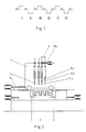
Figur 1 das Schema einer sechshübigen Kurbelwelle undFigur 2 eine Härtevorrichtung schematisch in Seitenansicht.
- Figure 1 is a schematic of a six-stroke crankshaft and
- Figure 2 shows a curing device schematically in side view.
Die sechshübige Kurbelwelle hat nach Figur 1 sechs Hublager I bis VI und sieben Hauptlager a. Die erfindungsgemäße Härtesequenz erfaßt das paarweise Härten der Hublagerflächen I mit VI, II mit V und III mit IV in beliebiger Reihenfolge. Werden bei einem Härtevorgang jeweils zwei Hublagerflächen und anschließend jeweils zwei Hauptlagerflächen gehärtet, so umfaßt die gesamte Härtesequenz sieben Härtevorgänge, nämlich drei für Hublagerflächenpaare, drei für die Hauptlagerflächenpaare und zusätzlich einen Härtevorgang für das siebente Hauptlager.According to FIG. 1, the six-stroke crankshaft has six pin bearings I to VI and seven main bearings a. The hardening sequence according to the invention covers the hardening of the pin bearing surfaces I with VI, II with V and III with IV in pairs in any order. If two stroke bearing surfaces and then two main bearing surfaces are hardened during a hardening process, the entire hardening sequence comprises seven hardening processes, namely three for stroke bearing surface pairs, three for the main bearing surface pairs and one hardening process for the seventh main bearing.
Werden mit den Hublagern jeweils ein benachbartes Hauptlager gehärtet, so umfaßt die gesamte Härtesequenz nur vier Härtevorgänge.If an adjacent main bearing is hardened with the pin bearings, the entire hardening sequence comprises only four hardening processes.
Zur Ausführung des geschilderten Härteverfahrens umfaßt die Härtevorrichtung in bekannter Weise zwei auf einem Maschinenbett M relativ zueinander verschiebbare Spannköpfe 1,2 zum beidendigen Einspannen der um ihre Achse drehbar gelagerten Kurbelwelle 3.To carry out the hardening process described, the hardening device comprises, in a known manner, two
Parallel zur Kurbelwelle 3 ist ein Härtewagen 4 mittels eines Antriebs 5 verfahrbar angeordnet, auf dem im dargestellten Ausführungsbeispiel vier Induktorgehänge 6,7 mit integrierten Abschreckbrausen angeordnet sind. Die Induktoren sind vom bekannten auf der zu härtenden Werkstückoberfläche aufgesetzten reitenden halboffenen Typ mit einem Parallelogrammgehänge, welches es ermöglicht, daß der Induktor, auf den ausmittigen Hublagerzapfen I bis VI sitzend, die Umlaufbewegung des Hublagerzapfens mitmachen kann.Parallel to the
Zwei Induktoren 6a,6b dienen zum Härten der Hublagerzapfen und zwei Induktoren 7a,7b sind für das Härten der Hauptlagerzapfen bestimmt. Ein Induktor 6a für das Hublagerhärten und ein Induktor 7a für das Hauptlagerhärten sind auf dem Wagen 4 ortsfest angeordnet. Die beiden übrigen Induktoren 6b,7b sind mittels eines Antriebes 8b und einer ggf. verstellbaren mechanischen Kopplung q relativ zueinander und zu den ortsfesten Induktoren 6a,7a verschiebbar am Härtewagen 4 angeordnet.Two inductors 6a, 6b are used for hardening the pin journals and two
Für den Fall der gleichzeitigen Härtung von Hub- und Hauptlagern kann das Abstandsmaß von Hub- und Hauptlagergehänge in Relation zu den jeweiligen Kurbelwellenmaßen durch Verknüpfen der Induktoren oder durch Verstellen der Abstandsmaße zwischen den Gehängen erfolgen. Dann kann je nach Bedarf sowohl eine manuell zu betätigende mechanische Einrichtung als auch eine servogetriebene evt. NC-gesteuerte Einrichtung sinnvoll sein.In the case of simultaneous hardening of the lifting and main bearings, the distance between the lifting and main bearing hangers can be made in relation to the respective crankshaft dimensions by linking the inductors or by adjusting the distance between the hangers. Then, depending on requirements, both a manually operated mechanical device and a servo-driven, possibly NC-controlled device can be useful.
Das Ausrichten der Induktoren zu den zu härtenden Lagerstellen geht so vonstatten, daß der Härtewagen 4 zunächst soweit gegenüber der eingespannten Kurbelwelle 3 verfahren wird, bis die ortsfesten Induktoren 6a,7a die zu härtenden Lagerstellen erreicht haben. Anschließend werden die beiden übrigen Induktoren 6b,7b auf die beiden anderen zu härtenden Lagerstellen ausgerichtet und dazu mittels des Antriebes 8b in Achsrichtung der Kurbelwelle 3 verschoben.Aligning the inductors with the bearing points to be hardened takes place in such a way that the hardening carriage 4 is first moved relative to the
Obwohl das erfindungsgemäße Verfahren und die Vorrichtung anhand der Härtung von sechshübigen Kurbelwellen beschrieben wurde, ergibt die Anwendung für das Härten von Kurbelwellen mit anderen Hubzahlen den gleichen Vorteil einer schnelleren verzugsarmen produktionssteigernden Härtung der Lagerstellen.Although the method and the device according to the invention have been described on the basis of the hardening of six-stroke crankshafts, the application for hardening crankshafts with different stroke numbers gives the same advantage of a faster, low-distortion, production-increasing hardening of the bearing points.
Claims (8)
- A process for the low distortion hardening of crankshafts by the sequential electric inductive heating of the crank and main bearing faces followed by quenching characterized in that all the crank bearing surfaces (I-VI) are hardened with only two inductors (6a, 6b) each pair of crank bearing surfaces lying symmetrically of the centre of the axis being hardened simultaneously.
- A process for the low distortion hardening of 6-stroke crankshafts according to claim 1, characterized in that the crank bearing surfaces (I-VI) are hardened in pairs, namely the outer surfaces (I, VI), the middle surfaces (II, V) and the inner surfaces (III, IV).
- A process according to claims 1 or 2, characterized in that the main bearing surfaces (a) are also hardened in pairs with only two inductors (7a, 7b).
- A process according to one of claims 1 to 3, characterized in that the hardening of the bearing surfaces (I-VI, a) in pairs is performed in the inward sequence.
- A device for the electric induction heating of the bearing surfaces of a crankshaft clamped to rotate around its axis by means of moving inductors which are disposed on a hardening carriage movable in the axial direction of the clamped crankshaft, and also by spraying water on the hardening carriage to quench the heated bearing surfaces for the purpose of surface hardening, characterized in that two inductors (6a, 6b) are provided on the hardening carriage (4) for hardening the crank bearing surfaces (I-VI), of which at least one inductor (6b) is disposed on the hardening carriage displaceably in the axial direction of the crankshaft (5) in relation to the or each other inductor.
- A device according to claim 4, characterized in that two additional inductors (7a, 7b) are provided for hardening the main bearing surfaces (a).
- A device according to claim 6, characterized in that at least one of the additional inductors 7b can be displaced on the hardening carriage (4) in the axial direction of the crankshaft (3).
- A device according to claims 5 or 6, characterized in that a mechanical, hydraulic or pneumatic numerically controlled drive (8b) is provided for displacing the inductors (6b, 7b) on the hardening carriage (4).
Applications Claiming Priority (2)
| Application Number | Priority Date | Filing Date | Title |
|---|---|---|---|
| DE3842808 | 1988-12-20 | ||
| DE3842808A DE3842808C1 (en) | 1988-12-20 | 1988-12-20 |
Publications (2)
| Publication Number | Publication Date |
|---|---|
| EP0374373A1 EP0374373A1 (en) | 1990-06-27 |
| EP0374373B1 true EP0374373B1 (en) | 1993-01-07 |
Family
ID=6369583
Family Applications (1)
| Application Number | Title | Priority Date | Filing Date |
|---|---|---|---|
| EP89116413A Expired - Lifetime EP0374373B1 (en) | 1988-12-20 | 1989-09-06 | Process and device for the low distortion hardening of crankshafts |
Country Status (4)
| Country | Link |
|---|---|
| EP (1) | EP0374373B1 (en) |
| JP (1) | JPH02200736A (en) |
| DE (2) | DE3842808C1 (en) |
| ES (1) | ES2037924T3 (en) |
Families Citing this family (9)
| Publication number | Priority date | Publication date | Assignee | Title |
|---|---|---|---|---|
| DE4001887A1 (en) * | 1990-01-23 | 1991-07-25 | Kessler Kg Maschf | METHOD AND DEVICE FOR INDUCTIVE HARDENING |
| JPH05247524A (en) * | 1992-03-06 | 1993-09-24 | Fuji Denshi Kogyo Kk | Method and device for high frequency induction heating and high frequency induction hardening of crankshaft |
| JP2542117Y2 (en) * | 1992-05-22 | 1997-07-23 | 富士電子工業株式会社 | Induction hardening device for crankshaft |
| DE4228093C1 (en) * | 1992-08-24 | 1993-04-08 | Aeg-Elotherm Gmbh, 5630 Remscheid, De | Hardening of bearing surfaces of different size crankshaft - comprises two inductor sets, each inductor is adapted for a specific crankshaft having associated transformers, connecting lead, cooling and quenching pipes, etc. |
| JP2764673B2 (en) * | 1992-12-14 | 1998-06-11 | 富士電子工業株式会社 | Induction hardening device for crankshaft |
| DE19808763C1 (en) | 1998-03-02 | 1999-04-22 | Aeg Elotherm Gmbh | Apparatus for hardening cylindrical bearing surfaces of shaft |
| DE10024990C5 (en) * | 2000-05-19 | 2020-04-30 | Maschinenfabrik Alfing Kessler Gmbh | Method and device for induction hardening of crankshafts |
| CN101880761A (en) * | 2010-06-13 | 2010-11-10 | 哈尔滨轴承集团公司 | Texture thinning processor for large bearing material |
| CN102676784B (en) * | 2012-05-09 | 2014-08-20 | 陕西北方动力有限责任公司 | Stagger crankshaft connecting rod neck quenching method based on KWH (Kilowatt Hour) semiautomatic quenching machine tool |
Family Cites Families (5)
| Publication number | Priority date | Publication date | Assignee | Title |
|---|---|---|---|---|
| DE1209137B (en) * | 1959-08-19 | 1966-01-20 | Deutsche Edelstahlwerke Ag | Method and device for inductive hardening of bearings on cranked shafts |
| DE1207716B (en) * | 1962-04-19 | 1965-12-23 | Deutsche Edelstahlwerke Ag | Crankshaft and method of hardening it |
| DE3135879A1 (en) * | 1981-09-10 | 1982-10-28 | Daimler-Benz Ag, 7000 Stuttgart | Device for the uniform and/or low-distortion inductive hardening of crank pins |
| US4749419A (en) * | 1986-08-28 | 1988-06-07 | Sommer Richard A | Method for heat treating rail |
| DE3737694C1 (en) * | 1987-11-06 | 1988-10-13 | Aeg Elotherm Gmbh | Method for operating an induction hardening device for crankshafts and such a device |
-
1988
- 1988-12-20 DE DE3842808A patent/DE3842808C1/de not_active Expired
-
1989
- 1989-09-06 EP EP89116413A patent/EP0374373B1/en not_active Expired - Lifetime
- 1989-09-06 DE DE8989116413T patent/DE58903232D1/en not_active Expired - Fee Related
- 1989-09-06 ES ES198989116413T patent/ES2037924T3/en not_active Expired - Lifetime
- 1989-12-18 JP JP1326221A patent/JPH02200736A/en active Pending
Also Published As
| Publication number | Publication date |
|---|---|
| DE58903232D1 (en) | 1993-02-18 |
| ES2037924T3 (en) | 1993-07-01 |
| DE3842808C1 (en) | 1989-08-31 |
| EP0374373A1 (en) | 1990-06-27 |
| JPH02200736A (en) | 1990-08-09 |
Similar Documents
| Publication | Publication Date | Title |
|---|---|---|
| DE1652618A1 (en) | Stretching and bending device | |
| EP0374373B1 (en) | Process and device for the low distortion hardening of crankshafts | |
| DE69704690T2 (en) | Process for the production of a hollow turbine blade and plant for the continuous heat-shrinking | |
| DE10024990C5 (en) | Method and device for induction hardening of crankshafts | |
| EP0394531B1 (en) | Seaming machine | |
| EP0070409A1 (en) | Method and device for induction-hardening elongated thin-walled workpieces | |
| DE69305359T2 (en) | UNIVERSAL SUPPORT AND ADJUSTING DEVICE FOR TOOLS IN A BENDING MACHINE FOR BENDING LONGER ELEMENTS | |
| DE68903494T2 (en) | MACHINE FOR CUTTING GRANITE BLOCK OR STONE MATERIALS IN PANELS. | |
| DE2833181C2 (en) | Forging press for forging a shaft flange | |
| DE2806987A1 (en) | DEVICE FOR MANIPULATING WORK PIECES | |
| DE19800885A1 (en) | Device for finishing peripheral surfaces on rotating workpieces, in particular for finishing cam discs and cams of a camshaft | |
| DE3617468C1 (en) | Inductor device | |
| EP0248983A1 (en) | Method and apparatus for rolling profiles in cylindrical work pieces | |
| DE2625022A1 (en) | DEVICE FOR SHAPING METALLIC WORKPIECES | |
| EP0530383A1 (en) | Method and device for forming workpieces | |
| DE69216301T3 (en) | Method of manufacturing a pulley, device for manufacturing the same and pulley thus manufactured | |
| DE1963979A1 (en) | Hydraulic forging machine for hot forging of rod-shaped and rod-shaped workpieces | |
| DE1117354B (en) | Method and machine for producing bare bar material for automatic lathes or similar machines | |
| DE1148960B (en) | Machine for forming sheet metal strips | |
| AT250130B (en) | Process, tool and machine for removing material from workpieces | |
| DE1935396B2 (en) | DEVICE FOR PREVENTING AND OR ELIMINATING SHAPED STUDS OF RING-SHAPED PRECISION BODIES IN PARTICULAR WAELZ BEARING RINGS DURING THE HARDENING OF THE SAME | |
| DE2203646A1 (en) | Machine for polishing surfaces | |
| DE2442033C3 (en) | Device for a model copying machine for producing workpieces from wood | |
| DE1909625C3 (en) | Stretch forging machine with at least two opposing oscillating jaws | |
| DE10010380B4 (en) | Press for turning and calibrating a workpiece |
Legal Events
| Date | Code | Title | Description |
|---|---|---|---|
| PUAI | Public reference made under article 153(3) epc to a published international application that has entered the european phase |
Free format text: ORIGINAL CODE: 0009012 |
|
| AK | Designated contracting states |
Kind code of ref document: A1 Designated state(s): DE ES FR GB IT SE |
|
| 17P | Request for examination filed |
Effective date: 19900807 |
|
| 17Q | First examination report despatched |
Effective date: 19920611 |
|
| GRAA | (expected) grant |
Free format text: ORIGINAL CODE: 0009210 |
|
| AK | Designated contracting states |
Kind code of ref document: B1 Designated state(s): DE ES FR GB IT SE |
|
| PG25 | Lapsed in a contracting state [announced via postgrant information from national office to epo] |
Ref country code: FR Free format text: THE PATENT HAS BEEN ANNULLED BY A DECISION OF A NATIONAL AUTHORITY Effective date: 19930107 |
|
| REF | Corresponds to: |
Ref document number: 58903232 Country of ref document: DE Date of ref document: 19930218 |
|
| GBT | Gb: translation of ep patent filed (gb section 77(6)(a)/1977) |
Effective date: 19930121 |
|
| ITF | It: translation for a ep patent filed | ||
| ET | Fr: translation filed | ||
| REG | Reference to a national code |
Ref country code: ES Ref legal event code: FG2A Ref document number: 2037924 Country of ref document: ES Kind code of ref document: T3 |
|
| PG25 | Lapsed in a contracting state [announced via postgrant information from national office to epo] |
Ref country code: GB Effective date: 19930906 |
|
| PG25 | Lapsed in a contracting state [announced via postgrant information from national office to epo] |
Ref country code: SE Effective date: 19930907 Ref country code: ES Free format text: LAPSE BECAUSE OF THE APPLICANT RENOUNCES Effective date: 19930907 |
|
| PLBE | No opposition filed within time limit |
Free format text: ORIGINAL CODE: 0009261 |
|
| STAA | Information on the status of an ep patent application or granted ep patent |
Free format text: STATUS: NO OPPOSITION FILED WITHIN TIME LIMIT |
|
| 26N | No opposition filed | ||
| GBPC | Gb: european patent ceased through non-payment of renewal fee |
Effective date: 19930906 |
|
| PG25 | Lapsed in a contracting state [announced via postgrant information from national office to epo] |
Ref country code: DE Effective date: 19940601 |
|
| REG | Reference to a national code |
Ref country code: FR Ref legal event code: ST |
|
| EUG | Se: european patent has lapsed |
Ref document number: 89116413.9 Effective date: 19940410 |
|
| REG | Reference to a national code |
Ref country code: ES Ref legal event code: FD2A Effective date: 19991007 |
|
| PG25 | Lapsed in a contracting state [announced via postgrant information from national office to epo] |
Ref country code: IT Free format text: LAPSE BECAUSE OF NON-PAYMENT OF DUE FEES;WARNING: LAPSES OF ITALIAN PATENTS WITH EFFECTIVE DATE BEFORE 2007 MAY HAVE OCCURRED AT ANY TIME BEFORE 2007. THE CORRECT EFFECTIVE DATE MAY BE DIFFERENT FROM THE ONE RECORDED. Effective date: 20050906 |