EP0372149A2 - Apparatus and method of breaking pieces of solid mineral material in fragments, and method of sorting fragments of solid mineral material according to size - Google Patents
Apparatus and method of breaking pieces of solid mineral material in fragments, and method of sorting fragments of solid mineral material according to size Download PDFInfo
- Publication number
- EP0372149A2 EP0372149A2 EP89104643A EP89104643A EP0372149A2 EP 0372149 A2 EP0372149 A2 EP 0372149A2 EP 89104643 A EP89104643 A EP 89104643A EP 89104643 A EP89104643 A EP 89104643A EP 0372149 A2 EP0372149 A2 EP 0372149A2
- Authority
- EP
- European Patent Office
- Prior art keywords
- mineral material
- solid mineral
- rotor
- pieces
- fragments
- Prior art date
- Legal status (The legal status is an assumption and is not a legal conclusion. Google has not performed a legal analysis and makes no representation as to the accuracy of the status listed.)
- Granted
Links
Images

Classifications
-
- B—PERFORMING OPERATIONS; TRANSPORTING
- B04—CENTRIFUGAL APPARATUS OR MACHINES FOR CARRYING-OUT PHYSICAL OR CHEMICAL PROCESSES
- B04B—CENTRIFUGES
- B04B3/00—Centrifuges with rotary bowls in which solid particles or bodies become separated by centrifugal force and simultaneous sifting or filtering
- B04B3/06—Centrifuges with rotary bowls in which solid particles or bodies become separated by centrifugal force and simultaneous sifting or filtering discharging solid particles by vibrating the bowl
-
- B—PERFORMING OPERATIONS; TRANSPORTING
- B02—CRUSHING, PULVERISING, OR DISINTEGRATING; PREPARATORY TREATMENT OF GRAIN FOR MILLING
- B02C—CRUSHING, PULVERISING, OR DISINTEGRATING IN GENERAL; MILLING GRAIN
- B02C19/00—Other disintegrating devices or methods
- B02C19/16—Mills provided with vibrators
-
- B—PERFORMING OPERATIONS; TRANSPORTING
- B02—CRUSHING, PULVERISING, OR DISINTEGRATING; PREPARATORY TREATMENT OF GRAIN FOR MILLING
- B02C—CRUSHING, PULVERISING, OR DISINTEGRATING IN GENERAL; MILLING GRAIN
- B02C13/00—Disintegrating by mills having rotary beater elements ; Hammer mills
- B02C13/14—Disintegrating by mills having rotary beater elements ; Hammer mills with vertical rotor shaft, e.g. combined with sifting devices
- B02C13/18—Disintegrating by mills having rotary beater elements ; Hammer mills with vertical rotor shaft, e.g. combined with sifting devices with beaters rigidly connected to the rotor
- B02C13/1807—Disintegrating by mills having rotary beater elements ; Hammer mills with vertical rotor shaft, e.g. combined with sifting devices with beaters rigidly connected to the rotor the material to be crushed being thrown against an anvil or impact plate
- B02C13/1835—Disintegrating by mills having rotary beater elements ; Hammer mills with vertical rotor shaft, e.g. combined with sifting devices with beaters rigidly connected to the rotor the material to be crushed being thrown against an anvil or impact plate by means of beater or impeller elements fixed in between an upper and lower rotor disc
-
- B—PERFORMING OPERATIONS; TRANSPORTING
- B02—CRUSHING, PULVERISING, OR DISINTEGRATING; PREPARATORY TREATMENT OF GRAIN FOR MILLING
- B02C—CRUSHING, PULVERISING, OR DISINTEGRATING IN GENERAL; MILLING GRAIN
- B02C19/00—Other disintegrating devices or methods
-
- B—PERFORMING OPERATIONS; TRANSPORTING
- B02—CRUSHING, PULVERISING, OR DISINTEGRATING; PREPARATORY TREATMENT OF GRAIN FOR MILLING
- B02C—CRUSHING, PULVERISING, OR DISINTEGRATING IN GENERAL; MILLING GRAIN
- B02C13/00—Disintegrating by mills having rotary beater elements ; Hammer mills
- B02C13/14—Disintegrating by mills having rotary beater elements ; Hammer mills with vertical rotor shaft, e.g. combined with sifting devices
- B02C13/18—Disintegrating by mills having rotary beater elements ; Hammer mills with vertical rotor shaft, e.g. combined with sifting devices with beaters rigidly connected to the rotor
- B02C13/1807—Disintegrating by mills having rotary beater elements ; Hammer mills with vertical rotor shaft, e.g. combined with sifting devices with beaters rigidly connected to the rotor the material to be crushed being thrown against an anvil or impact plate
- B02C2013/1885—Disintegrating by mills having rotary beater elements ; Hammer mills with vertical rotor shaft, e.g. combined with sifting devices with beaters rigidly connected to the rotor the material to be crushed being thrown against an anvil or impact plate of dead bed type
Definitions
- the present invention relates to apparatus and method of breaking pieces of solid mineral material by feeding pieces of solid mineral material along the axle of a rotor and rotating said rotor at an increased speed to throw said pieces of solid mineral material from the radial outlets of said rotor in tangential directions to cause said pieces of solid mineral material to strike against the "dead bed" of fragments of solid mineral material which encircles said rotor and cause said pieces of solid mineral material to reduce to fragments, and method of sorting resulting fragments of solid mineral material according to size.
- fragments of solid mineral material is heaped up to encircle a rotor and the rotor is made to rotate to throw pieces of solid mineral material to the heap or "dead bed” of fragments. Then, these pieces of solid mineral material strike the "dead bed” to reduce to fragments, which are allowed to fall from the space between the rotor and the breaking chamber. After leaving the lower part of the breaking apparatus the fragments of solid mineral material are sorted according to size.
- breaking force available in such a breaking apparatus will depend on the force with which pieces of solid mineral material can strike against the "dead bed”, and as a matter of course, the breaking g effect increases with the striking force.
- the "dead bed”, however, will be covered thick with fragments of relatively small size because collision takes place on the surface of the "dead bed”. Therefore pieces of solid mineral material when thrown at the "dead bed” are likely to land soft on the "dead bed", thereby causing thrown pieces of solid mineral material to lose their kinetic energy, which otherwise, would be used to break pieces of solid mineral material into fragments.
- one object of the present invention is to provide solid mineral material breaking apparatus and method which can make full use of the kinetic energy of thrown pieces of mineral material in breaking themselves in fragments, thereby substantially increasing the breaking efficiency.
- Another object of the present invention is to provide a method of sorting fragments of solid mineral material according to size.
- a centrifugal breaking apparatus including. in a breaking chamber, a rotor and a hopper arranged to supply pieces of solid mineral material along the axle of said rotor, thereby permitting said rotor when rotating at an increased speed, to throw said pieces of solid mineral material from the radial outlets of said rotor in tangential directions to cause said pieces of solid mineral material to strike against the "dead bed" of fragments of solid mineral material which encircles said rotor, and cause said pieces of solid mineral material to reduce to fragments, characterized in that said breaking chamber is open at its bottom floor and that said centrifugal breaking apparatus comprises a vibrator, said breaking chamber having a support box fixed to its undersurface, said support box being connected to said vibrator.
- centrifugal breaking apparatus which has a frame structure isolated from the breaking chamber, but still supporting the breaking chamber so as to permit the vibration of the breaking chamber as separate from the frame structure.
- a centrifugal breaking apparatus which has upper and lower frame sections and that the upper frame section has a breaking chamber formed therein.
- a centrifugal breaking apparatus which has a vibrating frame structure and a vibrator, said vibrator along with a rotor drive motor being connected to the frame structure.
- a method of breaking pieces of solid mineral material by feeding pieces of solid mineral material along the axle of a rotor and rotating said rotor at an increased speed to throw said pieces of solid mineral material from the radial outlets of said rotor in tangential directions to cause said pieces of solid mineral material to strike against the "dead bed" of fragments of solid mineral material which encircles said rotor and cause said pieces of solid mineral material to reduce to fragments, characterized in that said "dead bed" of fragments of solid mineral material is subjected to vibration.
- the "dead bed” is subjected to vibration to cause fragments of relatively large size to come up on the surface of the "dead bed”, and therefore, pieces of solid mineral material when thrown to the "dead bed", will strike against relatively large fragments on the surface of the "dead bed” so that the kinetic energy of the flying pieces of solid mineral material may be fully used in breaking themselves into fragments.
- the breaking efficiency will be substantially increased.
- a fragment-sorting method in combination with such a breaking method just described in which fragment-sorting method a separator plate is provided on the course on which fragments of solid mineral material fall from the "dead bed", and when the "dead bed” is subjected to vibration, fragments of relatively large size will come up on the surface of the "dead bed” to permit these fragments of relatively large size to fall inside and fragments of relatively small size to fall outside of the separator plate.
- a fragment-sorting method in combination with such a breaking method as described above in which fragment-sortering method an outlet is provided in the vicinity of the "dead bed", and when the "dead bed” is subjected to vibration, fragments of relatively large size will come up on the surface of the "dead bed” to leave fragments of relatively small size inside and fall from the outlet.
- fragments of relatively large size which come up on the surface of the "dead bed” as a result of vibration, will be automatically selected and removed as separate from fragments of relatively small size, which are left inside the "dead bed” as a result of the vibration.
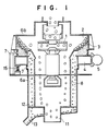
- Fig. 1 shows a centrifugal breaking apparatus according to one embodiment of the present invention as including a rotor 1 in a breaking chamber 2.
- the rotor 1 is designed to be driven at an increased speed by an associated motor (not shown).
- a hopper is arranged above the rotor 1 to supply pieces of solid mineral material along the axle of the rotor, thereby permitting the rotor 1 when rotating at an increased speed to throw pieces of solid mineral material from its radial outlets in tangential directions to cause pieces of solid mineral material to strike against the "dead bed" 3 of fragments of solid mineral material which encircles the rotor 1. Then, the pieces of solid mineral material reduce to fragments.
- the centrifugal breaking apparatus has lower and upper frame sections 5a and 8b coupled together.
- the breaking chamber 2 is built in the upper frame section 5b.
- the hopper (not shown) is connected to the top of the upper frame section 6b to supply pieces of solid mineral material along the axle of the rotor 1 as described above.
- the lower frame section 8a has an outlet 11 at the center of the bottom of the lower frame section, an annular opening 12 encircling the outlet 11 and a chute 13 to collect fragments of solid mineral material falling from the annular opening 12.
- the breaking chamber 2 of the upper frame section 5b is open at its bottom floor, and the opening of the bottom floor is encircled by a cylindrical wall.
- the breaking chamber 2 has an annular support box 4 connected to its undersurface.
- the annular support box 4 is resiliently supported by springs 15 as indicated at the lower frame section 6a, thus preventing transmission of vibration to the lower frame section 5a.
- the support box 4 is connected to a vibrator 5, which comprises a motor and an associated eccentric can to vibrate the "dead bed" vertically.
- the support box 4 is also connected to the upper and lower frame sections 6b and 8a by flexible material such as rubber plates 7, thereby permitting the vertical vibration of the annular box 4.
- the lower frame section 6a has a cylindrical separator 8 arranged coaxial with the lower frame section.
- Fig. 2 shows the relationship between the fragment size and the weight of fragments of diffferent sizes.
- Curve 1 shows the result of a conventional centrifugal breaking system using no vibration whereas curves 2 shows the results of a centrifugal breaking system using vibration according to the present invention.
- Taff having been supplied to the rotor, particulars of the experiments are as follows:
- the rate of fragments of relatively small size is large in a centrifugal breaking apparatus using vibration according to the present invention. compared with a conventional centrifugal breaking apparatus using no vibration. This shows that pieces of solid mineral material reduce to fragments at an increased efficiency in the centrifugal breaking apparatus using vibration according to the present invention.
- This particular embodiment uses a cylindrical separator to separate fragments of solid mineral material according to size.
- an outlet may be provided to the support box or the side wall of the breaking chamber to allow fragments of relatively small size to leave the "dead bed” while fragments of relatively large size slide and roll on the slant of the "dead bed” to fall in the center hollow space of the centrifugal breaking apparatus. If occasions demand, a net may be applied to the outlet of the breaking apparatus, thereby screening fragments of solid mineral material.
- This particular embodiment uses a support box as vibrating means.
- the breaking chamber, the upper frame section having a braking chamber, or the framework itself may be designed to vibrate.
- a motor for driving the rotor is fixed to the framework so as to vibrate together while rotating the rotor.
Abstract
Description
- The present invention relates to apparatus and method of breaking pieces of solid mineral material by feeding pieces of solid mineral material along the axle of a rotor and rotating said rotor at an increased speed to throw said pieces of solid mineral material from the radial outlets of said rotor in tangential directions to cause said pieces of solid mineral material to strike against the "dead bed" of fragments of solid mineral material which encircles said rotor and cause said pieces of solid mineral material to reduce to fragments, and method of sorting resulting fragments of solid mineral material according to size.
- In a conventional method of breaking pieces of solid mineral material into fragments, fragments of solid mineral material is heaped up to encircle a rotor and the rotor is made to rotate to throw pieces of solid mineral material to the heap or "dead bed" of fragments. Then, these pieces of solid mineral material strike the "dead bed" to reduce to fragments, which are allowed to fall from the space between the rotor and the breaking chamber. After leaving the lower part of the breaking apparatus the fragments of solid mineral material are sorted according to size.
- The breaking force available in such a breaking apparatus will depend on the force with which pieces of solid mineral material can strike against the "dead bed", and as a matter of course, the breaking g effect increases with the striking force. The "dead bed", however, will be covered thick with fragments of relatively small size because collision takes place on the surface of the "dead bed". Therefore pieces of solid mineral material when thrown at the "dead bed" are likely to land soft on the "dead bed", thereby causing thrown pieces of solid mineral material to lose their kinetic energy, which otherwise, would be used to break pieces of solid mineral material into fragments.
- Also, disadvantageously fragments of different sizes are mixed, and therefore, subsequent screening is necessitated
- With the above in mind one object of the present invention is to provide solid mineral material breaking apparatus and method which can make full use of the kinetic energy of thrown pieces of mineral material in breaking themselves in fragments, thereby substantially increasing the breaking efficiency. Another object of the present invention is to provide a method of sorting fragments of solid mineral material according to size.
- According to a first aspect of the present invention there is provided a centrifugal breaking apparatus including. in a breaking chamber, a rotor and a hopper arranged to supply pieces of solid mineral material along the axle of said rotor, thereby permitting said rotor when rotating at an increased speed, to throw said pieces of solid mineral material from the radial outlets of said rotor in tangential directions to cause said pieces of solid mineral material to strike against the "dead bed" of fragments of solid mineral material which encircles said rotor, and cause said pieces of solid mineral material to reduce to fragments, characterized in that said breaking chamber is open at its bottom floor and that said centrifugal breaking apparatus comprises a vibrator, said breaking chamber having a support box fixed to its undersurface, said support box being connected to said vibrator. According to a second aspect of the present invention there is provided such a centrifugal breaking apparatus which has a frame structure isolated from the breaking chamber, but still supporting the breaking chamber so as to permit the vibration of the breaking chamber as separate from the frame structure. According to a third aspect of the present invention there is provided such a centrifugal breaking apparatus which has upper and lower frame sections and that the upper frame section has a breaking chamber formed therein.
- According to a fourth aspect of the present invention there is provided such a centrifugal breaking apparatus which has a vibrating frame structure and a vibrator, said vibrator along with a rotor drive motor being connected to the frame structure.
- According to a fifth aspect of the present invention there is provided a method of breaking pieces of solid mineral material by feeding pieces of solid mineral material along the axle of a rotor and rotating said rotor at an increased speed to throw said pieces of solid mineral material from the radial outlets of said rotor in tangential directions to cause said pieces of solid mineral material to strike against the "dead bed" of fragments of solid mineral material which encircles said rotor and cause said pieces of solid mineral material to reduce to fragments, characterized in that said "dead bed" of fragments of solid mineral material is subjected to vibration. In the breaking apparatus and method just described, the "dead bed" is subjected to vibration to cause fragments of relatively large size to come up on the surface of the "dead bed", and therefore, pieces of solid mineral material when thrown to the "dead bed", will strike against relatively large fragments on the surface of the "dead bed" so that the kinetic energy of the flying pieces of solid mineral material may be fully used in breaking themselves into fragments. Thus. the breaking efficiency will be substantially increased.
- According to a sixth aspect of the present invention there is provided a fragment-sorting method in combination with such a breaking method just described in which fragment-sorting method a separator plate is provided on the course on which fragments of solid mineral material fall from the "dead bed", and when the "dead bed" is subjected to vibration, fragments of relatively large size will come up on the surface of the "dead bed" to permit these fragments of relatively large size to fall inside and fragments of relatively small size to fall outside of the separator plate. Finally, according to a seventh aspect of the present invention there is provided a fragment-sorting method in combination with such a breaking method as described above in which fragment-sortering method an outlet is provided in the vicinity of the "dead bed", and when the "dead bed" is subjected to vibration, fragments of relatively large size will come up on the surface of the "dead bed" to leave fragments of relatively small size inside and fall from the outlet. In the fragment-sorting method just described, fragments of relatively large size which come up on the surface of the "dead bed" as a result of vibration, will be automatically selected and removed as separate from fragments of relatively small size, which are left inside the "dead bed" as a result of the vibration.
- Other objects and advantages of the present invention will be understood from the following description of a breaking apparatus according to one embodiment of the present invention, which is shown in the accompanying drawings:
- Fig. 1 is a longitudinal section of a breaking apparatus according to one embodiment of the present invention; and
- Fig. 2 is a graphic representation showing the distribution of fragment sizes in a conventional breaking method and a breaking method using vibration of the "dead bed" according to the present invention.
- Fig. 1 shows a centrifugal breaking apparatus according to one embodiment of the present invention as including a rotor 1 in a
breaking chamber 2. The rotor 1 is designed to be driven at an increased speed by an associated motor (not shown). A hopper is arranged above the rotor 1 to supply pieces of solid mineral material along the axle of the rotor, thereby permitting the rotor 1 when rotating at an increased speed to throw pieces of solid mineral material from its radial outlets in tangential directions to cause pieces of solid mineral material to strike against the "dead bed" 3 of fragments of solid mineral material which encircles the rotor 1. Then, the pieces of solid mineral material reduce to fragments. - As shown, the centrifugal breaking apparatus has lower and upper frame sections 5a and 8b coupled together. The
breaking chamber 2 is built in the upper frame section 5b. The hopper (not shown) is connected to the top of theupper frame section 6b to supply pieces of solid mineral material along the axle of the rotor 1 as described above. The lower frame section 8a has anoutlet 11 at the center of the bottom of the lower frame section, anannular opening 12 encircling theoutlet 11 and achute 13 to collect fragments of solid mineral material falling from theannular opening 12. - As shown, the
breaking chamber 2 of the upper frame section 5b is open at its bottom floor, and the opening of the bottom floor is encircled by a cylindrical wall. Thebreaking chamber 2 has anannular support box 4 connected to its undersurface. Theannular support box 4 is resiliently supported bysprings 15 as indicated at thelower frame section 6a, thus preventing transmission of vibration to the lower frame section 5a. Thesupport box 4 is connected to avibrator 5, which comprises a motor and an associated eccentric can to vibrate the "dead bed" vertically. Thesupport box 4 is also connected to the upper andlower frame sections 6b and 8a by flexible material such asrubber plates 7, thereby permitting the vertical vibration of theannular box 4. - The
lower frame section 6a has a cylindrical separator 8 arranged coaxial with the lower frame section. When thesupport box 4 vibrates, fragments of relatively large size come up on the surface of the "dead bed" to fall inside the cylindrical separator 8 whereas fragments of relatively small size fall between the cylindrical separator 8 and the lower frame section 6. Then, the fragments of relatively large size are ejected from theexit 11 of the breaking system whereas the fragments of relatively small size are ejected from thechute 13. - Fig. 2 shows the relationship between the fragment size and the weight of fragments of diffferent sizes. Curve 1 shows the result of a conventional centrifugal breaking system using no vibration whereas
curves 2 shows the results of a centrifugal breaking system using vibration according to the present invention. Taff having been supplied to the rotor, particulars of the experiments are as follows: - Feeding rate of pieces of solid mineral material 40t/h
Circumferential speed of the rotor 55m/sec
Amplitude of the vibration of thesupport box 2. 5mm
Frequency of vibration 58Hz - As seen from Fig. 2, the rate of fragments of relatively small size is large in a centrifugal breaking apparatus using vibration according to the present invention. compared with a conventional centrifugal breaking apparatus using no vibration. This shows that pieces of solid mineral material reduce to fragments at an increased efficiency in the centrifugal breaking apparatus using vibration according to the present invention.
- This particular embodiment uses a cylindrical separator to separate fragments of solid mineral material according to size. In place of the cylindrical separator, however, an outlet may be provided to the support box or the side wall of the breaking chamber to allow fragments of relatively small size to leave the "dead bed" while fragments of relatively large size slide and roll on the slant of the "dead bed" to fall in the center hollow space of the centrifugal breaking apparatus. If occasions demand, a net may be applied to the outlet of the breaking apparatus, thereby screening fragments of solid mineral material.
- This particular embodiment uses a support box as vibrating means. Alternatively the breaking chamber, the upper frame section having a braking chamber, or the framework itself may be designed to vibrate. When the framework is designed to vibrate as a whole, a motor for driving the rotor is fixed to the framework so as to vibrate together while rotating the rotor.
Claims (7)
Applications Claiming Priority (2)
| Application Number | Priority Date | Filing Date | Title |
|---|---|---|---|
| JP308501/88 | 1988-12-05 | ||
| JP63308501A JPH0783837B2 (en) | 1988-12-05 | 1988-12-05 | Centrifugal crusher and its crushing method and crushed piece sorting method |
Publications (3)
| Publication Number | Publication Date |
|---|---|
| EP0372149A2 true EP0372149A2 (en) | 1990-06-13 |
| EP0372149A3 EP0372149A3 (en) | 1991-01-23 |
| EP0372149B1 EP0372149B1 (en) | 1994-08-17 |
Family
ID=17981776
Family Applications (1)
| Application Number | Title | Priority Date | Filing Date |
|---|---|---|---|
| EP89104643A Expired - Lifetime EP0372149B1 (en) | 1988-12-05 | 1989-03-15 | Apparatus and method of breaking pieces of solid mineral material in fragments, and method of sorting fragments of solid mineral material according to size |
Country Status (9)
| Country | Link |
|---|---|
| EP (1) | EP0372149B1 (en) |
| JP (1) | JPH0783837B2 (en) |
| KR (1) | KR930009716B1 (en) |
| AT (1) | ATE110008T1 (en) |
| AU (1) | AU620600B2 (en) |
| DE (2) | DE68917566T2 (en) |
| ES (1) | ES2017447T3 (en) |
| NZ (1) | NZ228547A (en) |
| ZA (1) | ZA893124B (en) |
Cited By (4)
| Publication number | Priority date | Publication date | Assignee | Title |
|---|---|---|---|---|
| US5145118A (en) * | 1990-08-29 | 1992-09-08 | Canada Larry D | Centrifugal impactor for crushing rocks |
| CN101745970B (en) * | 2009-12-11 | 2013-02-06 | 武汉理工大学 | Method for preparing reformed ceramic raw material powder and the vibration and reformation device thereof |
| CN108906227A (en) * | 2018-07-05 | 2018-11-30 | 福建南方路面机械有限公司 | A kind of vertical shaft crusher and its breaking method |
| CN113289725A (en) * | 2021-05-18 | 2021-08-24 | 华能云南滇东能源有限责任公司 | Environment-friendly anthracite treatment device |
Families Citing this family (2)
| Publication number | Priority date | Publication date | Assignee | Title |
|---|---|---|---|---|
| CN113399030B (en) * | 2021-06-15 | 2023-06-13 | 南京华云新工程科技有限公司 | Pharmacy is with medicament collection equipment that mills |
| CN114086009B (en) * | 2021-10-26 | 2022-06-21 | 辽宁科技学院 | Hypereutectic aluminum-silicon alloy production device and process |
Citations (3)
| Publication number | Priority date | Publication date | Assignee | Title |
|---|---|---|---|---|
| DE2808350A1 (en) * | 1978-02-27 | 1979-08-30 | Klein Alb Kg | Crushing reclaimed sand lumps in foundries - using air streams to remove dust before crushed sand is sieved |
| EP0093013A2 (en) * | 1982-04-27 | 1983-11-02 | Kotobuki Engineering & Manufacturing Co Ltd | Method of withdrawing particulate material from dead-bed of centrifugal crusher and centrifugal crusher suitable for carrying the method into practice |
| EP0216592A2 (en) * | 1985-09-17 | 1987-04-01 | Allen Bryan Bartley | Method of and apparatus for breaking/shattering stone |
Family Cites Families (3)
| Publication number | Priority date | Publication date | Assignee | Title |
|---|---|---|---|---|
| AU498906B2 (en) * | 1976-12-24 | 1979-03-29 | Iowa Manufacturing Co. | Impact crusher |
| AT390568B (en) * | 1986-10-30 | 1990-05-25 | Wageneder Sbm Gmbh | IMPACT MILL FOR CRUSHING STONE OD. DGL. |
| FR2610217B1 (en) * | 1987-01-30 | 1991-08-16 | Alsthom | ROTARY CRUSHER WITH SELF-PROTECTED SPRAY BLADES |
-
1988
- 1988-12-05 JP JP63308501A patent/JPH0783837B2/en not_active Expired - Lifetime
-
1989
- 1989-03-15 DE DE68917566T patent/DE68917566T2/en not_active Expired - Fee Related
- 1989-03-15 AT AT89104643T patent/ATE110008T1/en not_active IP Right Cessation
- 1989-03-15 DE DE198989104643T patent/DE372149T1/en active Pending
- 1989-03-15 EP EP89104643A patent/EP0372149B1/en not_active Expired - Lifetime
- 1989-03-15 ES ES89104643T patent/ES2017447T3/en not_active Expired - Lifetime
- 1989-03-30 NZ NZ228547A patent/NZ228547A/en unknown
- 1989-03-31 KR KR1019890002029A patent/KR930009716B1/en not_active IP Right Cessation
- 1989-04-06 AU AU32527/89A patent/AU620600B2/en not_active Ceased
- 1989-04-27 ZA ZA893124A patent/ZA893124B/en unknown
Patent Citations (3)
| Publication number | Priority date | Publication date | Assignee | Title |
|---|---|---|---|---|
| DE2808350A1 (en) * | 1978-02-27 | 1979-08-30 | Klein Alb Kg | Crushing reclaimed sand lumps in foundries - using air streams to remove dust before crushed sand is sieved |
| EP0093013A2 (en) * | 1982-04-27 | 1983-11-02 | Kotobuki Engineering & Manufacturing Co Ltd | Method of withdrawing particulate material from dead-bed of centrifugal crusher and centrifugal crusher suitable for carrying the method into practice |
| EP0216592A2 (en) * | 1985-09-17 | 1987-04-01 | Allen Bryan Bartley | Method of and apparatus for breaking/shattering stone |
Cited By (5)
| Publication number | Priority date | Publication date | Assignee | Title |
|---|---|---|---|---|
| US5145118A (en) * | 1990-08-29 | 1992-09-08 | Canada Larry D | Centrifugal impactor for crushing rocks |
| CN101745970B (en) * | 2009-12-11 | 2013-02-06 | 武汉理工大学 | Method for preparing reformed ceramic raw material powder and the vibration and reformation device thereof |
| CN108906227A (en) * | 2018-07-05 | 2018-11-30 | 福建南方路面机械有限公司 | A kind of vertical shaft crusher and its breaking method |
| CN108906227B (en) * | 2018-07-05 | 2023-09-19 | 福建南方路面机械股份有限公司 | Vertical shaft type crusher and crushing method thereof |
| CN113289725A (en) * | 2021-05-18 | 2021-08-24 | 华能云南滇东能源有限责任公司 | Environment-friendly anthracite treatment device |
Also Published As
| Publication number | Publication date |
|---|---|
| EP0372149A3 (en) | 1991-01-23 |
| DE372149T1 (en) | 1990-12-20 |
| NZ228547A (en) | 1991-12-23 |
| KR900009141A (en) | 1990-07-02 |
| ES2017447A4 (en) | 1991-02-16 |
| ATE110008T1 (en) | 1994-09-15 |
| JPH0783837B2 (en) | 1995-09-13 |
| AU620600B2 (en) | 1992-02-20 |
| JPH02152558A (en) | 1990-06-12 |
| DE68917566D1 (en) | 1994-09-22 |
| AU3252789A (en) | 1990-06-07 |
| EP0372149B1 (en) | 1994-08-17 |
| KR930009716B1 (en) | 1993-10-09 |
| DE68917566T2 (en) | 1995-01-12 |
| ZA893124B (en) | 1989-12-27 |
| ES2017447T3 (en) | 1994-10-16 |
Similar Documents
| Publication | Publication Date | Title |
|---|---|---|
| US3941689A (en) | Apparatus for sorting waste for disposal | |
| EP0372149A2 (en) | Apparatus and method of breaking pieces of solid mineral material in fragments, and method of sorting fragments of solid mineral material according to size | |
| US4515316A (en) | Method of withdrawing particulate material from dead-bed of centrifugal crusher and centrifugal crusher suitable for carrying the method into practice | |
| EP0157647B1 (en) | Comminuting | |
| CN201295624Y (en) | Rotary bastard coal smash separator | |
| JPH11147045A (en) | Pulverizing device | |
| JPH06320112A (en) | Sorting device | |
| CN212018041U (en) | Solid waste treatment device | |
| US5522513A (en) | Separator disc | |
| CN211329537U (en) | Civil engineering construction waste treatment device | |
| JP3189088B2 (en) | Glass crushing equipment and glass crushing method | |
| JPH06509506A (en) | Stationary cone crusher | |
| JP2004313896A (en) | Method and equipment for separate treatment of gypsum wall board | |
| RU2146225C1 (en) | Method and device for mechanical cleaning of powder from impurities in the form of particles sticking to it | |
| JPH03118848A (en) | Assorting treatment apparatus for empty bottle, or the like | |
| JP3259223B2 (en) | Gypsum board sorting machine | |
| CN220836043U (en) | Screening plant for coarse crusher | |
| RU202398U1 (en) | Hammer crusher | |
| CN220177137U (en) | Balanced feeding device of impact crusher | |
| CN220443971U (en) | Impact crusher | |
| JPH02174948A (en) | Centrifugal crusher | |
| SU633600A1 (en) | Separating crusher | |
| US3087683A (en) | Vibrating crushers | |
| JPH0510924Y2 (en) | ||
| JP2555979Y2 (en) | Rotor in centrifugal crusher |
Legal Events
| Date | Code | Title | Description |
|---|---|---|---|
| PUAI | Public reference made under article 153(3) epc to a published international application that has entered the european phase |
Free format text: ORIGINAL CODE: 0009012 |
|
| AK | Designated contracting states |
Kind code of ref document: A2 Designated state(s): AT CH DE ES FR GB IT LI SE |
|
| ITCL | It: translation for ep claims filed |
Representative=s name: SOCIETA' ITALIANA BREVETTI S.P.A. |
|
| EL | Fr: translation of claims filed | ||
| TCAT | At: translation of patent claims filed | ||
| PUAL | Search report despatched |
Free format text: ORIGINAL CODE: 0009013 |
|
| DET | De: translation of patent claims | ||
| AK | Designated contracting states |
Kind code of ref document: A3 Designated state(s): AT CH DE ES FR GB IT LI SE |
|
| 17P | Request for examination filed |
Effective date: 19910712 |
|
| 17Q | First examination report despatched |
Effective date: 19920601 |
|
| ITTA | It: last paid annual fee | ||
| GRAA | (expected) grant |
Free format text: ORIGINAL CODE: 0009210 |
|
| RAP1 | Party data changed (applicant data changed or rights of an application transferred) |
Owner name: KOTOBUKI ENGINEERING & MANUFACTURING CO LTD |
|
| AK | Designated contracting states |
Kind code of ref document: B1 Designated state(s): AT CH DE ES FR GB IT LI SE |
|
| REF | Corresponds to: |
Ref document number: 110008 Country of ref document: AT Date of ref document: 19940915 Kind code of ref document: T |
|
| REF | Corresponds to: |
Ref document number: 68917566 Country of ref document: DE Date of ref document: 19940922 |
|
| REG | Reference to a national code |
Ref country code: ES Ref legal event code: FG2A Ref document number: 2017447 Country of ref document: ES Kind code of ref document: T3 |
|
| ET | Fr: translation filed | ||
| ITF | It: translation for a ep patent filed |
Owner name: SOCIETA' ITALIANA BREVETTI S.P.A. |
|
| PGFP | Annual fee paid to national office [announced via postgrant information from national office to epo] |
Ref country code: FR Payment date: 19950116 Year of fee payment: 7 |
|
| EAL | Se: european patent in force in sweden |
Ref document number: 89104643.5 |
|
| PGFP | Annual fee paid to national office [announced via postgrant information from national office to epo] |
Ref country code: GB Payment date: 19950222 Year of fee payment: 7 |
|
| PGFP | Annual fee paid to national office [announced via postgrant information from national office to epo] |
Ref country code: SE Payment date: 19950324 Year of fee payment: 7 Ref country code: AT Payment date: 19950324 Year of fee payment: 7 |
|
| PGFP | Annual fee paid to national office [announced via postgrant information from national office to epo] |
Ref country code: ES Payment date: 19950331 Year of fee payment: 7 |
|
| PGFP | Annual fee paid to national office [announced via postgrant information from national office to epo] |
Ref country code: CH Payment date: 19950418 Year of fee payment: 7 |
|
| PGFP | Annual fee paid to national office [announced via postgrant information from national office to epo] |
Ref country code: DE Payment date: 19950529 Year of fee payment: 7 |
|
| PLBE | No opposition filed within time limit |
Free format text: ORIGINAL CODE: 0009261 |
|
| STAA | Information on the status of an ep patent application or granted ep patent |
Free format text: STATUS: NO OPPOSITION FILED WITHIN TIME LIMIT |
|
| 26N | No opposition filed | ||
| PG25 | Lapsed in a contracting state [announced via postgrant information from national office to epo] |
Ref country code: GB Effective date: 19960315 Ref country code: AT Effective date: 19960315 |
|
| PG25 | Lapsed in a contracting state [announced via postgrant information from national office to epo] |
Ref country code: SE Effective date: 19960316 Ref country code: ES Free format text: LAPSE BECAUSE OF NON-PAYMENT OF DUE FEES Effective date: 19960316 |
|
| PG25 | Lapsed in a contracting state [announced via postgrant information from national office to epo] |
Ref country code: LI Effective date: 19960331 Ref country code: CH Effective date: 19960331 |
|
| GBPC | Gb: european patent ceased through non-payment of renewal fee |
Effective date: 19960315 |
|
| REG | Reference to a national code |
Ref country code: CH Ref legal event code: PL |
|
| PG25 | Lapsed in a contracting state [announced via postgrant information from national office to epo] |
Ref country code: FR Effective date: 19961129 |
|
| PG25 | Lapsed in a contracting state [announced via postgrant information from national office to epo] |
Ref country code: DE Effective date: 19961203 |
|
| EUG | Se: european patent has lapsed |
Ref document number: 89104643.5 |
|
| REG | Reference to a national code |
Ref country code: FR Ref legal event code: ST |
|
| REG | Reference to a national code |
Ref country code: ES Ref legal event code: FD2A Effective date: 19990405 |
|
| PG25 | Lapsed in a contracting state [announced via postgrant information from national office to epo] |
Ref country code: IT Free format text: LAPSE BECAUSE OF NON-PAYMENT OF DUE FEES;WARNING: LAPSES OF ITALIAN PATENTS WITH EFFECTIVE DATE BEFORE 2007 MAY HAVE OCCURRED AT ANY TIME BEFORE 2007. THE CORRECT EFFECTIVE DATE MAY BE DIFFERENT FROM THE ONE RECORDED. Effective date: 20050315 |