EP0371277B1 - Device for indicating the loading state of a lorry - Google Patents
Device for indicating the loading state of a lorry Download PDFInfo
- Publication number
- EP0371277B1 EP0371277B1 EP89120383A EP89120383A EP0371277B1 EP 0371277 B1 EP0371277 B1 EP 0371277B1 EP 89120383 A EP89120383 A EP 89120383A EP 89120383 A EP89120383 A EP 89120383A EP 0371277 B1 EP0371277 B1 EP 0371277B1
- Authority
- EP
- European Patent Office
- Prior art keywords
- vehicle frame
- distance
- axles
- weight
- axle
- Prior art date
- Legal status (The legal status is an assumption and is not a legal conclusion. Google has not performed a legal analysis and makes no representation as to the accuracy of the status listed.)
- Expired - Lifetime
Links
Images
Classifications
-
- B—PERFORMING OPERATIONS; TRANSPORTING
- B60—VEHICLES IN GENERAL
- B60T—VEHICLE BRAKE CONTROL SYSTEMS OR PARTS THEREOF; BRAKE CONTROL SYSTEMS OR PARTS THEREOF, IN GENERAL; ARRANGEMENT OF BRAKING ELEMENTS ON VEHICLES IN GENERAL; PORTABLE DEVICES FOR PREVENTING UNWANTED MOVEMENT OF VEHICLES; VEHICLE MODIFICATIONS TO FACILITATE COOLING OF BRAKES
- B60T8/00—Arrangements for adjusting wheel-braking force to meet varying vehicular or ground-surface conditions, e.g. limiting or varying distribution of braking force
- B60T8/18—Arrangements for adjusting wheel-braking force to meet varying vehicular or ground-surface conditions, e.g. limiting or varying distribution of braking force responsive to vehicle weight or load, e.g. load distribution
- B60T8/1837—Arrangements for adjusting wheel-braking force to meet varying vehicular or ground-surface conditions, e.g. limiting or varying distribution of braking force responsive to vehicle weight or load, e.g. load distribution characterised by the load-detecting arrangements
-
- B—PERFORMING OPERATIONS; TRANSPORTING
- B60—VEHICLES IN GENERAL
- B60T—VEHICLE BRAKE CONTROL SYSTEMS OR PARTS THEREOF; BRAKE CONTROL SYSTEMS OR PARTS THEREOF, IN GENERAL; ARRANGEMENT OF BRAKING ELEMENTS ON VEHICLES IN GENERAL; PORTABLE DEVICES FOR PREVENTING UNWANTED MOVEMENT OF VEHICLES; VEHICLE MODIFICATIONS TO FACILITATE COOLING OF BRAKES
- B60T17/00—Component parts, details, or accessories of power brake systems not covered by groups B60T8/00, B60T13/00 or B60T15/00, or presenting other characteristic features
- B60T17/18—Safety devices; Monitoring
- B60T17/22—Devices for monitoring or checking brake systems; Signal devices
-
- G—PHYSICS
- G01—MEASURING; TESTING
- G01G—WEIGHING
- G01G19/00—Weighing apparatus or methods adapted for special purposes not provided for in the preceding groups
- G01G19/08—Weighing apparatus or methods adapted for special purposes not provided for in the preceding groups for incorporation in vehicles
-
- B—PERFORMING OPERATIONS; TRANSPORTING
- B60—VEHICLES IN GENERAL
- B60G—VEHICLE SUSPENSION ARRANGEMENTS
- B60G2400/00—Indexing codes relating to detected, measured or calculated conditions or factors
- B60G2400/60—Load
- B60G2400/61—Load distribution
-
- B—PERFORMING OPERATIONS; TRANSPORTING
- B60—VEHICLES IN GENERAL
- B60G—VEHICLE SUSPENSION ARRANGEMENTS
- B60G2401/00—Indexing codes relating to the type of sensors based on the principle of their operation
Definitions
- the invention relates to a loading-load condition indicator device for trucks, preferably the weight of the payload taken up by refuse collection vehicles, the vehicle frames of which are movable relative to the axles and supported on them by springs, a device being provided which measures the distance between the vehicle frame and the axle or axles generates a signal when the distance has been reduced to an amount equal to the weight of the maximum permissible payload.
- the total weight can usually only be maintained if the weight of the load is known. However, since the weight of the load is unknown in many cases, only a rough estimate of the actual total weight can be made, which often leads to the permissible total weight being exceeded or not being reached, with the result that loading capacity is wasted .
- this object is achieved in a device of the generic type by the features of the characterizing part of claim 1.
- This device is characterized by a particularly simple construction because the existing vehicle suspension is used to assess the loading condition.
- Trucks are usually provided with a linkage attached to an axle, which controls a load-dependent brake in accordance with the deflection of the vehicle frame.
- an actuator is connected to the linkage of the load-dependent brake, which actuates or activates a switch or an initiator when the distance between the vehicle frame and the one or more axles has been reduced to a dimension that corresponds to the weight corresponds to the maximum permissible payload.
- the actuator advantageously consists of a sheet metal or the like, which interacts without contact with an inductive initiator.
- Such a device is insensitive to contamination.
- the activated switch or initiator closes a display circuit when the truck brake is applied.
- This configuration increases the reliability of the display, because when the truck brake is applied, the display is generally only in the idle state of the vehicle, so that dynamic influences, which can result, for example, from oscillating movements of the vehicle frame or impacts acting on the axles, are excluded.
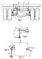
- the vehicle frame 2 which carries the body or the loading area 1, is supported on the vehicle axle 5 via the leaf spring assemblies 3, 4 in the usual and therefore not described in detail.
- the distance between the vehicle frame 3 and the axle 5 decreases in accordance with the weight of the payload taken up.
- a control valve 6 On the vehicle frame 3, a control valve 6 is attached, the controls the available brake pressure of the pneumatically braked rear axle.
- the upper end of a rod 8 At the free end of the pivotable control lever 7 of the control valve 6, the upper end of a rod 8 is articulated, the lower end of which is attached to the axle 4 or the housing of the differential gear.
- the rod 8 pivots the actuating lever 7 of the control valve 6 in accordance with the reduction or enlargement of the distance between the vehicle frame 2 and the axle 5 and thereby sets the correct braking pressure as a function of the load.
- a piece of sheet metal 9 is connected, which cooperates with the inductive initiator 10, which is attached to the vehicle frame 2 in a height-adjustable manner. As soon as the piece of sheet metal 9 reaches the effective range of the initiator 10, the latter generates a signal by changing the inductance, for example by closing a switch.
- the initiator 10 is connected to a circuit which is powered by the vehicle battery 11.
- the circuit is closed when switches actuated by the initiator 10 and the handbrake 12 are closed, so that a signal transmitter 13 located in the circuit receives the signal current required for display.
- the switch actuated by the handbrake 12 is closed when the handbrake is moved into its drawn position 12 'shown in broken lines.
- the initiator 10 is adjusted so that the sheet 9 comes into its effective area when the truck has taken up the maximum permissible payload and the vehicle frame is compressed accordingly.
- an accurate display ensures that within the scope of the legally required six-month brake tests, the dimension X of the transmission linkage of the load-dependent brake can be adjusted if necessary.
- the distance between the vehicle frame 2 and the axle 5 corresponding to the respective deflection can also be displayed with other transmission devices and switches in order to indicate the loading state or to achieve the maximum permissible total weight.
Abstract
Description
Die Erfindung betrifft eine Beladvugzustandsanzeigerorrichtung von LKW, vorzugsweise des Gewichts der aufgenommenen Nutzlast von Müllsammelfahrzeugen, deren Fahrzeugrahmen relativ zu den Achsen beweglich und auf diesen durch Federn abgestützt sind, wobei ein den Abstand zwischen dem Fahrzeugrahmen und der oder den Achsen erfassenden Einrichtung vorgesehen ist, die ein Signal erzeugt, wenn der Abstand auf ein Maß verringert worden ist, das dem Gewicht der höchstzulässigen Nutzlast entspricht.The invention relates to a loading-load condition indicator device for trucks, preferably the weight of the payload taken up by refuse collection vehicles, the vehicle frames of which are movable relative to the axles and supported on them by springs, a device being provided which measures the distance between the vehicle frame and the axle or axles generates a signal when the distance has been reduced to an amount equal to the weight of the maximum permissible payload.
Beim Beladen von Lastkraftwagen läßt sich üblicherweise das Gesamtgewicht nur dann einhalten, wenn das Gewicht der Ladung bekannt ist. Da jedoch in vielen Fällen das Gewicht der Ladung unbekannt ist, kann nur eine grobe Abschätzung des tatsächlichen Gesamtgewichtes vorgenommen werden, was häufig dazu führt, daß das zulässige Gesamtgewicht überschritten oder aber auch nicht erreicht wird, was dann zur Folge hat, daß Ladekapazität verschenkt wird.When loading trucks, the total weight can usually only be maintained if the weight of the load is known. However, since the weight of the load is unknown in many cases, only a rough estimate of the actual total weight can be made, which often leads to the permissible total weight being exceeded or not being reached, with the result that loading capacity is wasted .
Das Problem, den jeweiligen Beladungszustand abzuschätzen, um einerseits Überladungen zu vermeiden und andererseits die vorhandene Ladekapazität in optimaler Weise auszunutzen, besteht insbesondere bei Müllsammelfahrzeugen, da die Beladung durch das Einschütten des Inhalts von Müllsammelbehältern erfolgt, ohne daß der Fahrer die Möglichkeit hat, das Gewicht der aufgenommenen Gesamtmenge des Mülls zu beurteilen. Wird vor Erreichen des zulässigen Gesamtgewichts eine Deponie oder Verbrennungsanlage angefahren, wird in unwirtschaftlicher Weise Ladekapazität verschenkt. Wird die Ladekapazität jedoch überschritten, können neben den sich aus der Überladung ergebenden Gefahren die Straßen durch herabfallenden Müll verschmutzt werden und schließlich kann auch die Brems- und Hydraulikanlage des Fahrzeugs überlastet werden.The problem of estimating the respective loading condition in order to avoid overloading on the one hand and the existing one on the other To utilize the loading capacity in an optimal manner exists, in particular, in refuse collection vehicles, since the loading takes place by pouring the contents of refuse collection containers without the driver being able to assess the weight of the total quantity of refuse taken up. If a landfill or incineration plant is approached before the permissible total weight is reached, loading capacity is wasted in an uneconomical manner. If the loading capacity is exceeded, however, in addition to the dangers resulting from overloading, the streets can be contaminated by falling garbage and, ultimately, the vehicle's braking and hydraulic systems can also be overloaded.
Bereits aus der US-A-35 31 766 ist eine gattungsgemäße Vorrichtung zur Anzeige des Beladungszustandes von Lastwagen bekannt. Diese bekannte Anzeige des Beladungszustandes besteht im wesentlichen aus einem Elektromagneten, der an einer Achse fest angeklemmt ist und aus einem Stab, der an ein Trägerteil des Fahrzeugrahmens angeschweißt ist. Durch diese vorbekannte Anordnung der Anzeige des Beladungszustandes ergibt sich aber das Problem, daß das Abstandsverhältnis zwischen dem Stab und dem Elektromagneten bei der Erstmontage des LKWs fest eingestellt wird, sich allerdings während der Nutzung des Lastkraftwagens ein gebrauchsbedingtes Setzen der Blattfedern einstellt. Dadurch verringert sich der Abstand zwischen dem Fahrzeugrahmen und den Achsen, was bei der vorbekannten Anordnung zu einem zu fühen Auslösen des Warnsignals bei der Beladung des Lastkraftwagens führt.From US-A-35 31 766 a generic device for displaying the loading state of trucks is known. This known display of the loading condition consists essentially of an electromagnet which is firmly clamped to an axis and a rod which is welded to a carrier part of the vehicle frame. With this known arrangement of the display of the loading state, however, there is the problem that the distance ratio between the rod and the electromagnet is fixed when the truck is first assembled, but a usage-related setting of the leaf springs occurs during use of the truck. This reduces the distance between the vehicle frame and the axles, which, in the known arrangement, leads to a triggering of the warning signal when the truck is loaded.
Es stellt sich daher die Aufgabe, den gattungsgemäßen Stand der Technik derart weiterzubilden, daß eine einfach aufgebaute Vorrichtung an die Hand gegeben wird, bei der Meßfehler infolge des gebrauchsbedingten Setzens der Blattfedern des Lastkraftwagens ausgeglichen werden können.It is therefore the task of developing the generic prior art in such a way that a simply constructed device is provided, in which measuring errors due to the use-related setting of the leaf springs of the truck can be compensated for.
ErfindungsgemäB wird diese Aufgabe bei einer Vorrichtung der gattungsgemäBen Art durch die Merkmale des kennzeichnenden Teils des Anspruchs 1 gelöst. Diese Vorrichtung zeichnet sich durch einen besonders einfachen Aufbau aus, weil die vorhandene Fahrzeugfederung zur Beurteilung des Beladungszustandes verwendet wird.According to the invention, this object is achieved in a device of the generic type by the features of the characterizing part of claim 1. This device is characterized by a particularly simple construction because the existing vehicle suspension is used to assess the loading condition.
Üblicherweise sind Lastkraftwagen mit einem an einer Achse befestigten Gestänge versehen, das entsprechend der Einfederung des Fahrzeugrahmens eine lastabhängige Bremse steuert. Nach der Erfindung ist es vorgesehen, daß mit dem Gestänge der lastabhängigen Bremse ein Betätigungsglied verbunden ist, das einen Schalter oder einen Initiator betätigt oder aktiviert, wenn der Abstand zwischen dem Fahrzeugrahmen und der oder den Achsen auf ein Maß verringert worden ist, das dem Gewicht der höhstzulässigen Nutzlast entspricht.Trucks are usually provided with a linkage attached to an axle, which controls a load-dependent brake in accordance with the deflection of the vehicle frame. According to the invention, it is provided that an actuator is connected to the linkage of the load-dependent brake, which actuates or activates a switch or an initiator when the distance between the vehicle frame and the one or more axles has been reduced to a dimension that corresponds to the weight corresponds to the maximum permissible payload.
Zweckmäßigerweise besteht das Betätigungsglied aus einem Blech o.dgl., das berührungslos mit einem induktiven Initiator zusammenwirkt. Eine derartige Einrichtung ist verschmutzungsunempfindlich.The actuator advantageously consists of a sheet metal or the like, which interacts without contact with an inductive initiator. Such a device is insensitive to contamination.
In weiterer Ausgestaltung der Erfindung ist vorgesehen, daß der aktivierte Schalter oder Initiator einen Anzeigestromkreis schließt, wenn die Lkw-Bremse angezogen ist. Diese Ausgestaltung erhöht die Zuverlässigkeit der Anzeige, weil bei angezogener Lkw-Bremse grundsätzlich eine Anzeige nur im Ruhezustand des Fahrzeuges erfolgt, so daß dynamische Einflüsse, die sich beispielsweise aus schwingenden Bewegungen des Fahrzeugrahmens oder auf die Achsen wirkende Stöße ergeben können, ausgeschlossen sind.In a further embodiment of the invention it is provided that the activated switch or initiator closes a display circuit when the truck brake is applied. This configuration increases the reliability of the display, because when the truck brake is applied, the display is generally only in the idle state of the vehicle, so that dynamic influences, which can result, for example, from oscillating movements of the vehicle frame or impacts acting on the axles, are excluded.
Ein Ausführungsbeispiel der Erfindung wird nachstehend anhand der Zeichnung näher erläutert. In dieser zeigt
- Fig.1 eine Rückansicht eines auf die Hinterachse abgestützten Fahrzeugrahmens eine Lastkraftwagens,
- Fig.2 eine vergrößerte Darstellung des Gestänges der lastabhängigen Einstellvorrichtung der Bremse und
- Fig.3 eine schematisch Darstellung des Stromkreises zur Anzeige des höchstzulässigen Gesamtgewichts.
- 1 is a rear view of a vehicle frame supported on the rear axle of a truck,
- 2 shows an enlarged view of the linkage of the load-dependent adjusting device of the brake and
- 3 shows a schematic representation of the circuit for displaying the maximum permissible total weight.
Der den Aufbau oder die Ladefläche 1 tragende Fahrzeugrahmen 2 stützt sich in üblicher und daher nicht näher beschriebener Weise über die Blattfederpakete 3,4 auf die Fahrzeugachse 5 ab. Beim Beladen der Ladefläche 1, des Lastkraftwagens verringert sich entsprechend dem Gewicht der aufgenommenen Nutzlast der Abstand zwischen dem Fahrzeugrahmen 3 und der Achse 5.The
An dem Fahrzeugrahmen 3 ist ein Regelventil 6 befestigt, das den zur Verfügung stehenden Bremsdruck der pneumatisch gebremsten Hinterachse steuert. An das freie Ende des schwenkbaren Stellhebels 7 des Regelventils 6 ist das obere Ende einer Stange 8 angelenkt, deren unteres Ende an der Achse 4 bzw. dem Gehäuse des Differentialgetriebes befestigt ist. Die Stange 8 verschwenkt infolgedessen entsprechend der Verringerung oder Vergrößerung des Abstandes zwischen dem Fahrzeugrahmen 2 und der Achse 5 den Betätigungshebel 7 des Regelventils 6 und stellt dadurch in Abhängigkeit von der Last den richtigen Bremsdruck ein.On the vehicle frame 3, a
Mit dem oberen Ende der Stange 8 ist ein Blechstück 9 verbunden, das mit dem induktiven Initiator 10 zusammenwirkt, der höhenverstellbar an dem Fahrzeugrahmen 2 befestigt ist. Sobald das Blechstück 9 in den Wirkbereich des Initiators 10 gelangt, erzeugt dieser durch die Änderung der Induktivität ein Signal, beispielsweise durch Schließen eines Schalters.With the upper end of the rod 8, a piece of
Der Initiator 10 ist, wie aus Fig. 3 ersichtlich, in einen Stromkreis eingeschaltet, der von der Fahrzeugbatterie 11 mit Strom gespeist wird. Der Stromkreis wird geschlossen, wenn von dem Initiator 10 und der Handbremse 12 betätigte Schalter geschlossen sind, so daß ein in dem Stromkreis liegender Signalgeber 13 den zur Anzeige erforderlichen Signalstrom erhält. Der von der Handbremse 12 betätigte Schalter wird geschlossen, wenn die Handbremse in ihre gestrichelt eingezeichnete angezogene Stellung 12′ bewegt wird.As can be seen from FIG. 3, the
Der Initiator 10 wird so einjustiert, daß das Blech 9 in dessen Wirkbereich gerät, wenn der Lastkraftwagen die höchstzulässige Nutzlast aufgenommen hat und der Fahrzeugrahmen entsprechend eingefedert ist.The
Nach einer erforderlichen Grundeinstellung des Initiators 10 ist eine genaue Anzeige dadurch gewährleistet, daß im Rahmen der gesetzlich vorgeschriebenen halbjährlichen Bremsuntersuchungen das Maß X des Übertragungsgestänges der lastabhängigen Bremse erforderlichenfalls nachgestellt werden kann.After a basic setting of the
Der der jeweiligen Einfederung entsprechende Abstand zwischen dem Fahrzeugrahmen 2 und der Achse 5 kann zur Anzeige des Beladungszustandes bzw. des Erreichens des höchstzulässigen Gesamtgewichts auch mit anderen Übertragungseinrichtungen und Schaltern zur Anzeige gebracht werden.The distance between the
Claims (3)
characterized in
that the distance-detecting device comprises a linkage (7, 8) which is secured to an axle and which controls the brake of the truck in a load-dependent manner and in dependence on the spring-suspension movement of the vehicle frame, wherein an actuating member (9) is connected to the linkage member (8), which activates a swish or an initiator (10) for indicating the loading state when the distance between the vehicle frame (2) and the axle or axles (5) has been reduced to an extent which corresponds to the weight of the highest permissible useful load, and that the effective length (X) of the linkage member (8) is adjustable.
Priority Applications (1)
| Application Number | Priority Date | Filing Date | Title |
|---|---|---|---|
| AT89120383T ATE79675T1 (en) | 1988-11-28 | 1989-11-03 | DEVICE FOR INDICATION OF TRUCK LOAD STATUS. |
Applications Claiming Priority (2)
| Application Number | Priority Date | Filing Date | Title |
|---|---|---|---|
| DE3840112A DE3840112C1 (en) | 1988-11-28 | 1988-11-28 | |
| DE3840112 | 1988-11-28 |
Publications (3)
| Publication Number | Publication Date |
|---|---|
| EP0371277A2 EP0371277A2 (en) | 1990-06-06 |
| EP0371277A3 EP0371277A3 (en) | 1990-08-16 |
| EP0371277B1 true EP0371277B1 (en) | 1992-08-19 |
Family
ID=6368035
Family Applications (1)
| Application Number | Title | Priority Date | Filing Date |
|---|---|---|---|
| EP89120383A Expired - Lifetime EP0371277B1 (en) | 1988-11-28 | 1989-11-03 | Device for indicating the loading state of a lorry |
Country Status (5)
| Country | Link |
|---|---|
| US (1) | US5099221A (en) |
| EP (1) | EP0371277B1 (en) |
| AT (1) | ATE79675T1 (en) |
| DE (2) | DE3840112C1 (en) |
| ES (1) | ES2034560T3 (en) |
Cited By (1)
| Publication number | Priority date | Publication date | Assignee | Title |
|---|---|---|---|---|
| EP4103917A4 (en) * | 2020-02-14 | 2024-03-06 | Pedders Shock Absorber Service Pty Ltd | On-board vehicle scales |
Families Citing this family (15)
| Publication number | Priority date | Publication date | Assignee | Title |
|---|---|---|---|---|
| DE4033501C2 (en) * | 1990-10-20 | 1994-02-03 | Vc Recycling Patentverwertung | Method and device for sorted collection of waste using a multi-chamber vehicle |
| DE4208979A1 (en) * | 1992-03-20 | 1993-09-23 | Kloeckner Humboldt Deutz Ag | Measurement system for load on tractor vehicle and=or on front and=or rear wheel unit - contains pressure sensor in working cylinder of lifting device, force sensors in wheel units, calculation unit and display in cabin |
| GB2271189A (en) * | 1992-08-21 | 1994-04-06 | Hollowtech Limited | Axle load sensing arrangement |
| DE9213690U1 (en) * | 1992-10-10 | 1992-12-03 | Spitzer Silo-Fahrzeugwerk Gmbh & Co Kg, 6957 Elztal, De | |
| DE19839542A1 (en) * | 1998-08-31 | 2000-07-06 | Franz Rottner | Loading display/indicator for vehicles and supporters of every type that records at one or more measuring points |
| DE10341132A1 (en) | 2003-09-06 | 2005-03-31 | Daimlerchrysler Ag | Loading indicator of a vehicle |
| DE102005051964A1 (en) * | 2005-10-29 | 2007-05-03 | GM Global Technology Operations, Inc., Detroit | Driver assistance system used in a vehicle comprises a control device and axle sensors for determining the vehicle condition height from which each axle load is determined |
| GB2455073A (en) * | 2007-11-22 | 2009-06-03 | James Fraser Brown | Vehicle load monitor |
| DE102012023544A1 (en) | 2012-12-01 | 2014-06-05 | Man Truck & Bus Ag | Method and motor vehicle for detecting stresses occurring on a motor vehicle |
| CN103350664A (en) * | 2013-07-24 | 2013-10-16 | 苏州市润凯汽车配件制造有限公司 | Automobile chassis obstacle alarming system |
| GB2516654B (en) * | 2013-07-29 | 2015-08-19 | Ifor Williams Trailers Ltd | Axle clamping system for deflection sensing beam |
| US9969327B2 (en) | 2015-03-04 | 2018-05-15 | Auto Truck Group, Llc | Vehicle improper load sensor |
| DE102016005666A1 (en) * | 2016-04-30 | 2017-11-02 | Wabco Gmbh | Device for the electronic detection of the axle load of a motor vehicle |
| US10661808B2 (en) * | 2018-04-09 | 2020-05-26 | Arnold Chase | Dynamic vehicle separation system |
| US10730529B2 (en) | 2018-04-09 | 2020-08-04 | Arnold Chase | Dynamic vehicle separation system |
Family Cites Families (15)
| Publication number | Priority date | Publication date | Assignee | Title |
|---|---|---|---|---|
| US1168370A (en) * | 1912-07-23 | 1916-01-18 | Everett V Watson | Safety recording device. |
| DE927071C (en) * | 1952-03-13 | 1955-04-28 | Josef Dehnert | Load weight indicators for vehicles, in particular for trucks |
| US3531766A (en) * | 1967-09-27 | 1970-09-29 | Techmatic Corp | Overload indicator for vehicles |
| GB1292816A (en) * | 1969-03-13 | 1972-10-11 | Colchester Ltd Ellis | Apparatus for determining the load on a wheel axle in a vehicle |
| US3955636A (en) * | 1973-06-01 | 1976-05-11 | Malcolm Anthony Askew | Weighing apparatus for truck and vehicle loads |
| DE2419754A1 (en) * | 1974-04-24 | 1975-11-13 | Bosch Gmbh Robert | DEVICE FOR DETERMINING THE LOAD-DEPENDENT CHANGING DISTANCE BETWEEN THE VEHICLE AXLE AND THE BODY OF A VEHICLE |
| GB1541218A (en) * | 1975-06-03 | 1979-02-28 | Bendix Westinghouse Ltd | Load dependent control arrangements |
| ZA762936B (en) * | 1976-06-30 | 1977-10-26 | G Booke | The indication of axle loads in vehicles |
| IT1143485B (en) * | 1981-04-03 | 1986-10-22 | Ettore Cordiano | BRAKING SYSTEM FOR VEHICLES WITH BRAKE DISTRIBUTOR CONTROLLED BY ELECTRONIC PROCESSOR |
| US4553788A (en) * | 1984-06-29 | 1985-11-19 | Smith Frank R | Automatic air brake control |
| JPS6134425A (en) * | 1984-07-27 | 1986-02-18 | Komatsu Ltd | Load capacity measuring method of dump truck |
| CA1212418A (en) * | 1985-03-21 | 1986-10-07 | Chris R. Christen | Vehicle monitoring system |
| IT209873Z2 (en) * | 1987-01-16 | 1988-11-04 | Itt Ind Riunite Srl | CIRCUIT DEVICE FOR DETECTION OF VEHICLE STRUCTURE. |
| US4727352A (en) * | 1987-03-17 | 1988-02-23 | Doller Jerry A | Axle weight load indicator device |
| US5032821A (en) * | 1989-05-12 | 1991-07-16 | Domanico Edward J | Motor vehicle stability monitoring and alarm system and method |
-
1988
- 1988-11-28 DE DE3840112A patent/DE3840112C1/de not_active Expired - Fee Related
-
1989
- 1989-11-03 DE DE8989120383T patent/DE58902087D1/en not_active Expired - Fee Related
- 1989-11-03 EP EP89120383A patent/EP0371277B1/en not_active Expired - Lifetime
- 1989-11-03 AT AT89120383T patent/ATE79675T1/en not_active IP Right Cessation
- 1989-11-03 ES ES198989120383T patent/ES2034560T3/en not_active Expired - Lifetime
-
1991
- 1991-08-20 US US07/750,435 patent/US5099221A/en not_active Expired - Fee Related
Cited By (1)
| Publication number | Priority date | Publication date | Assignee | Title |
|---|---|---|---|---|
| EP4103917A4 (en) * | 2020-02-14 | 2024-03-06 | Pedders Shock Absorber Service Pty Ltd | On-board vehicle scales |
Also Published As
| Publication number | Publication date |
|---|---|
| ATE79675T1 (en) | 1992-09-15 |
| ES2034560T3 (en) | 1993-04-01 |
| US5099221A (en) | 1992-03-24 |
| DE3840112C1 (en) | 1990-01-25 |
| EP0371277A3 (en) | 1990-08-16 |
| DE58902087D1 (en) | 1992-09-24 |
| EP0371277A2 (en) | 1990-06-06 |
Similar Documents
| Publication | Publication Date | Title |
|---|---|---|
| EP0371277B1 (en) | Device for indicating the loading state of a lorry | |
| EP0241673B1 (en) | Brake control adjuster | |
| DE19741366C5 (en) | Brake pedal device | |
| EP0255624B1 (en) | Apparatus for discharging receptacles | |
| DE3806709A1 (en) | SHOCK ABSORBER FOR VEHICLES | |
| DE2642041A1 (en) | ACTUATING DEVICE FOR COMPRESSED BRAKE SYSTEM | |
| DE3108884A1 (en) | DEVICE FOR INFLUENCING THE ANGLE OF AN ARTICULATED VEHICLE | |
| DE2619775C2 (en) | ||
| DE4000073A1 (en) | Overload indicator for motor vehicle - has element on axles movable w.r.t. element on body, associated measurement arrangement e.g. switch with indicator lamp | |
| EP2994726A1 (en) | Elastically deformable load bearing structure comprising a measuring assembly for the load | |
| EP1247765B1 (en) | Load monitoring device for foot boards | |
| DE3722184C2 (en) | DEVICE FOR EMPTYING CONTAINERS | |
| DE2924825A1 (en) | Measuring lorry load wt. without fixed weighbridge - using hydraulic cylinders raising chassis w.r.t. suspension and measuring pressure | |
| DE102006023501B3 (en) | Running board device for vehicle, especially waste collection vehicle, has support arm spring-mounted on vehicle component | |
| DE2557348A1 (en) | COMPRESSED AIR BRAKE DEVICE FOR VEHICLES | |
| DE2629360C2 (en) | ||
| DE4204066A1 (en) | Measuring appts. for determining loaded wt. of vehicle esp. trailer vehicle - has piston-cylinder unit and indicates deflection of axle using scale proportional to loaded weight | |
| DE1030206B (en) | Measuring and display device on vehicles for determining the load weight | |
| DE3434349A1 (en) | Method for producing a force which assists in the steering of a motor vehicle when required, and device for carrying out the method | |
| DE1605278C3 (en) | Load-dependent controlled compressed air brake for vehicles, in particular rail vehicles with a spring brake cylinder | |
| DE3006638C2 (en) | trailer hitch | |
| AT242543B (en) | Device for the automatic adjustment of the braking force in vehicles depending on the respective load | |
| DE1135780B (en) | Device for stroke limitation on vehicle crank axles with air springs | |
| EP1510424A2 (en) | Support apparatus of a trailer tow bar | |
| DE2815527A1 (en) | CONTROL FOR THE BRAKE PRESSURE RELIEF VALVE OF MOTOR VEHICLES |
Legal Events
| Date | Code | Title | Description |
|---|---|---|---|
| PUAI | Public reference made under article 153(3) epc to a published international application that has entered the european phase |
Free format text: ORIGINAL CODE: 0009012 |
|
| AK | Designated contracting states |
Kind code of ref document: A2 Designated state(s): AT BE CH DE ES FR GB GR IT LI LU NL SE |
|
| PUAL | Search report despatched |
Free format text: ORIGINAL CODE: 0009013 |
|
| AK | Designated contracting states |
Kind code of ref document: A3 Designated state(s): AT BE CH DE ES FR GB GR IT LI LU NL SE |
|
| 17P | Request for examination filed |
Effective date: 19900820 |
|
| 17Q | First examination report despatched |
Effective date: 19910627 |
|
| GRAA | (expected) grant |
Free format text: ORIGINAL CODE: 0009210 |
|
| AK | Designated contracting states |
Kind code of ref document: B1 Designated state(s): AT BE CH DE ES FR GB GR IT LI LU NL SE |
|
| PG25 | Lapsed in a contracting state [announced via postgrant information from national office to epo] |
Ref country code: SE Free format text: THE PATENT HAS BEEN ANNULLED BY A DECISION OF A NATIONAL AUTHORITY Effective date: 19920819 Ref country code: NL Effective date: 19920819 Ref country code: GR Free format text: LAPSE BECAUSE OF FAILURE TO SUBMIT A TRANSLATION OF THE DESCRIPTION OR TO PAY THE FEE WITHIN THE PRESCRIBED TIME-LIMIT Effective date: 19920819 Ref country code: BE Effective date: 19920819 |
|
| REF | Corresponds to: |
Ref document number: 79675 Country of ref document: AT Date of ref document: 19920915 Kind code of ref document: T |
|
| ITF | It: translation for a ep patent filed |
Owner name: BUGNION S.P.A. |
|
| REF | Corresponds to: |
Ref document number: 58902087 Country of ref document: DE Date of ref document: 19920924 |
|
| GBT | Gb: translation of ep patent filed (gb section 77(6)(a)/1977) | ||
| PG25 | Lapsed in a contracting state [announced via postgrant information from national office to epo] |
Ref country code: AT Effective date: 19921103 |
|
| PG25 | Lapsed in a contracting state [announced via postgrant information from national office to epo] |
Ref country code: LU Free format text: LAPSE BECAUSE OF NON-PAYMENT OF DUE FEES Effective date: 19921130 Ref country code: LI Effective date: 19921130 Ref country code: CH Effective date: 19921130 |
|
| ET | Fr: translation filed | ||
| NLV1 | Nl: lapsed or annulled due to failure to fulfill the requirements of art. 29p and 29m of the patents act | ||
| REG | Reference to a national code |
Ref country code: ES Ref legal event code: FG2A Ref document number: 2034560 Country of ref document: ES Kind code of ref document: T3 |
|
| PLBE | No opposition filed within time limit |
Free format text: ORIGINAL CODE: 0009261 |
|
| STAA | Information on the status of an ep patent application or granted ep patent |
Free format text: STATUS: NO OPPOSITION FILED WITHIN TIME LIMIT |
|
| REG | Reference to a national code |
Ref country code: CH Ref legal event code: PL |
|
| 26N | No opposition filed | ||
| PGFP | Annual fee paid to national office [announced via postgrant information from national office to epo] |
Ref country code: GB Payment date: 19961028 Year of fee payment: 8 |
|
| PGFP | Annual fee paid to national office [announced via postgrant information from national office to epo] |
Ref country code: FR Payment date: 19961114 Year of fee payment: 8 |
|
| PGFP | Annual fee paid to national office [announced via postgrant information from national office to epo] |
Ref country code: ES Payment date: 19961118 Year of fee payment: 8 |
|
| PGFP | Annual fee paid to national office [announced via postgrant information from national office to epo] |
Ref country code: DE Payment date: 19961127 Year of fee payment: 8 |
|
| PG25 | Lapsed in a contracting state [announced via postgrant information from national office to epo] |
Ref country code: GB Free format text: LAPSE BECAUSE OF NON-PAYMENT OF DUE FEES Effective date: 19971103 |
|
| PG25 | Lapsed in a contracting state [announced via postgrant information from national office to epo] |
Ref country code: ES Free format text: LAPSE BECAUSE OF EXPIRATION OF PROTECTION Effective date: 19971104 |
|
| PG25 | Lapsed in a contracting state [announced via postgrant information from national office to epo] |
Ref country code: FR Free format text: THE PATENT HAS BEEN ANNULLED BY A DECISION OF A NATIONAL AUTHORITY Effective date: 19971130 |
|
| GBPC | Gb: european patent ceased through non-payment of renewal fee |
Effective date: 19971103 |
|
| PG25 | Lapsed in a contracting state [announced via postgrant information from national office to epo] |
Ref country code: DE Free format text: LAPSE BECAUSE OF NON-PAYMENT OF DUE FEES Effective date: 19980801 |
|
| REG | Reference to a national code |
Ref country code: FR Ref legal event code: ST |
|
| REG | Reference to a national code |
Ref country code: ES Ref legal event code: FD2A Effective date: 20010301 |
|
| PG25 | Lapsed in a contracting state [announced via postgrant information from national office to epo] |
Ref country code: IT Free format text: LAPSE BECAUSE OF NON-PAYMENT OF DUE FEES;WARNING: LAPSES OF ITALIAN PATENTS WITH EFFECTIVE DATE BEFORE 2007 MAY HAVE OCCURRED AT ANY TIME BEFORE 2007. THE CORRECT EFFECTIVE DATE MAY BE DIFFERENT FROM THE ONE RECORDED. Effective date: 20051103 |