EP0370420A1 - Einrichtung zum Vermeiden des Eingriffspiels zwischen Zahnrädern - Google Patents
Einrichtung zum Vermeiden des Eingriffspiels zwischen Zahnrädern Download PDFInfo
- Publication number
- EP0370420A1 EP0370420A1 EP89121398A EP89121398A EP0370420A1 EP 0370420 A1 EP0370420 A1 EP 0370420A1 EP 89121398 A EP89121398 A EP 89121398A EP 89121398 A EP89121398 A EP 89121398A EP 0370420 A1 EP0370420 A1 EP 0370420A1
- Authority
- EP
- European Patent Office
- Prior art keywords
- gear
- leg
- spring
- leg spring
- recesses
- Prior art date
- Legal status (The legal status is an assumption and is not a legal conclusion. Google has not performed a legal analysis and makes no representation as to the accuracy of the status listed.)
- Withdrawn
Links
Images

Classifications
-
- F—MECHANICAL ENGINEERING; LIGHTING; HEATING; WEAPONS; BLASTING
- F16—ENGINEERING ELEMENTS AND UNITS; GENERAL MEASURES FOR PRODUCING AND MAINTAINING EFFECTIVE FUNCTIONING OF MACHINES OR INSTALLATIONS; THERMAL INSULATION IN GENERAL
- F16H—GEARING
- F16H55/00—Elements with teeth or friction surfaces for conveying motion; Worms, pulleys or sheaves for gearing mechanisms
- F16H55/02—Toothed members; Worms
- F16H55/17—Toothed wheels
- F16H55/18—Special devices for taking up backlash
Definitions
- the invention relates to a device for avoiding the play on a gear meshing with a counter gear, according to the preamble of claim 1.
- Such a device is shown, for example, in DE-OS 28 13 456.
- a pin parallel to the axis of rotation is provided on the gear and on the toothed disk, which pins are braced against one another in the direction of rotation by a spring.
- the one pin must necessarily be passed through a recess in the adjacent gear.
- the device shown is unfavorable in terms of components, the spatial arrangement and in particular due to the complicated assembly.
- the object of the invention is to design a device of the generic type in such a way that it is particularly simple with reliable function in terms of manufacture and assembly.
- a recess which is axially parallel to the direction of rotation of the gearwheel and through which a U-shaped leg spring can be inserted is.
- One leg is supported on the gear wheel and the other leg on the toothed disk, whereby a considerable torsional moment can be generated.
- the recess can preferably be a simple bore into which the leg spring is inserted in a simple manner.
- the leg spring can also be designed as an axial securing device for the toothed lock washer.
- the toothed washer is thus held by the leg spring on the gear, so that the assembly unit thus formed can be quickly and easily assembled, for example in motor vehicle transmissions.
- leg spring and the recesses in the gear or in the toothed disc can be designed according to the features of claim 3, whereby a reliable axial locking can be achieved with little additional manufacturing effort.
- a locking pin in addition to the leg spring, a locking pin can also be provided, which on the one hand ensures the axial locking between the toothed wheel and toothed lock washer and on the other hand holds the leg spring after its assembly.
- This arrangement has the advantage that the recesses can be simple bores which are formed without cutting or cutting in the gear wheel or in the toothed disk.
- the locking pin in turn can be a sintered part, an investment casting or possibly a plastic part, onto which the lugs and stops required for the axial securing and for holding the leg spring are molded. Due to the features of claim 6, a secure positive connection of the leg spring and possibly the locking pin in the recess is produced in a simple manner. Slipping out is reliably avoided.
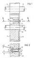
- FIG. 1 shows a spur gear drive with two helically toothed gears 12, 14 which mesh with one another.
- the gearwheels with the shafts 16, 18 carrying them can be part of a motor vehicle change gearbox.
- the gear wheel 14 has an annular collar 20, on which a toothed disk 22 is rotatably mounted.
- the toothed disc 22 has the same toothing as the gear 14 and is also in constant engagement with the gear 12.
- the gearwheel 14 is provided in its hub area with three recesses or bores 24 of the same geometry, each offset by 120 ° of its circumference (only one bore is shown in the drawing), which are aligned parallel to the axis of rotation 26 of the gearwheel 14.
- Corresponding recesses 28 are likewise machined in the toothed disk 22. The recesses 28 are positioned relative to the bores 24 in such a way that, when the gearing is operationally engaged, they are offset in relation to the bores 24 in the prestressing direction (cf. FIG. 2).
- a U-shaped leg spring 30 is inserted, which is made of spring steel.
- the leg spring 30 is supported with its one leg 32 on the bore 24, while the other leg 34 exerts a torsional moment on the toothed disc 22 with a defined prestressing force.
- a section 36 is provided on the leg 34 of the leg spring 30 which is bent by approximately 90 ° and which engages around the toothed disk 22 as shown. Furthermore, a tongue 38 protruding from the leg 32 is formed on the leg spring 30 and is supported as a stop surface on an annular shoulder 42 which results through the bore 24 and a bore 40 in the gearwheel 14 with a larger diameter.
- the height h of the tongue 38 protruding from the leg 32 at an angle of approximately 45 ° is greater than the gap s which defines the resilient free movement of the leg spring 30 in the recess 24. This is the spring 30 positively held in the recess 24.
- an adjustment hole can be provided in the toothed disk 22 and the gear wheel 14, into which an alignment pin is inserted during assembly. This ensures that gear 14 and toothed disc 22 are mounted in the structurally predetermined assignment to each other.
- toothed disc 22 is pushed onto the collar 20 of the gear 14 and, if necessary, the dowel pin mentioned is inserted. Then the leg springs 30 are pushed into the recesses 28 and 24 until the tongue 38 of each leg spring 30 engages on the ring shoulder 42. Thereafter, gear 14 and toothed disc 22 form an assembly unit.
- a locking pin 50 is used substantially semicircular cross-section, which engages with lugs 52, 54, the respective free end faces of the toothed disc 22 'or the gear 14'.
- the locking pin 50 has a cam-like elevation 56 with which it is supported in the bore 24 '.
- One of the bore 24 'recessed surface 58 engages the recess 28' (see also Fig. 4).
- the U-shaped leg spring 30 ' is supported with its one leg 32' on the in the annular collar 20 of the gear 14 'cutting hole 24', while the other leg 34 'on the locking pin 50 in the region of the recess 28' of the toothed disk engages .
- this is supported at its base region on a nose 60 of the locking pin 50.
- a slot-shaped recess 62 provided on the free end of the leg 34 'surrounds a relatively narrow nose 64 on the siche rungsw 50.
- the toothed disc 22 ' is first placed on the gear 14', which is rotatably mounted on the collar 20. With overlapping recesses 28 ', 24', the locking pin 50 is first inserted into the recesses until its lugs 52, 54, as shown in the drawing in Fig. 3, overlap the free end faces of the gear 14 'and the toothed disc 28'. Then the leg spring 30 'is inserted into the free space of the recesses 28', 24 'until the recess 62 in the leg 34' of the leg spring 30 'engages behind the nose 64 of the locking pin 50. In this position, the leg spring 30 'is axially secured against falling out.
Applications Claiming Priority (2)
| Application Number | Priority Date | Filing Date | Title |
|---|---|---|---|
| DE3839807 | 1988-11-25 | ||
| DE19883839807 DE3839807C1 (ja) | 1988-11-25 | 1988-11-25 |
Publications (1)
| Publication Number | Publication Date |
|---|---|
| EP0370420A1 true EP0370420A1 (de) | 1990-05-30 |
Family
ID=6367871
Family Applications (1)
| Application Number | Title | Priority Date | Filing Date |
|---|---|---|---|
| EP89121398A Withdrawn EP0370420A1 (de) | 1988-11-25 | 1989-11-18 | Einrichtung zum Vermeiden des Eingriffspiels zwischen Zahnrädern |
Country Status (2)
| Country | Link |
|---|---|
| EP (1) | EP0370420A1 (ja) |
| DE (1) | DE3839807C1 (ja) |
Cited By (1)
| Publication number | Priority date | Publication date | Assignee | Title |
|---|---|---|---|---|
| EP1516782A1 (de) * | 2003-09-19 | 2005-03-23 | Saia-Burgess Murten AG | Stellantrieb für eine Scheinwerfereinheit |
Families Citing this family (11)
| Publication number | Priority date | Publication date | Assignee | Title |
|---|---|---|---|---|
| DE102006058868B4 (de) | 2006-12-07 | 2008-10-16 | Getrag Getriebe- Und Zahnradfabrik Hermann Hagenmeyer Gmbh & Cie Kg | Rasselfreie Bauteilpaarung |
| DE202008010745U1 (de) | 2007-12-27 | 2009-05-07 | Getrag Getriebe- Und Zahnradfabrik Hermann Hagenmeyer Gmbh & Cie Kg | Rasselfreie Bauteilpaarung |
| DE102007063524A1 (de) | 2007-12-27 | 2009-07-09 | Getrag Getriebe- Und Zahnradfabrik Hermann Hagenmeyer Gmbh & Cie Kg | Rasselfreie Bauteilpaarung |
| DE102009015952B4 (de) | 2009-03-27 | 2013-05-16 | Getrag Getriebe- Und Zahnradfabrik Hermann Hagenmeyer Gmbh & Cie Kg | Rasselfreie Bauteilpaarung |
| DE102009061157B3 (de) * | 2009-03-27 | 2020-08-13 | Magna Pt B.V. & Co. Kg | Rasselfreie Bauteilpaarung |
| DE102009015947B4 (de) | 2009-03-27 | 2013-06-27 | Getrag Getriebe- Und Zahnradfabrik Hermann Hagenmeyer Gmbh & Cie Kg | Rasselfreie Bauteilpaarung |
| DE102009015946B4 (de) | 2009-03-27 | 2016-05-04 | Getrag Getriebe- Und Zahnradfabrik Hermann Hagenmeyer Gmbh & Cie Kg | Rasselfreie Bauteilpaarung |
| DE102009015948B4 (de) | 2009-03-27 | 2012-09-20 | Getrag Getriebe- Und Zahnradfabrik Hermann Hagenmeyer Gmbh & Co. Kg | Rasselfreie Bauteilpaarung |
| DE102009015958B4 (de) | 2009-03-27 | 2016-05-04 | Getrag Getriebe- Und Zahnradfabrik Hermann Hagenmeyer Gmbh & Cie Kg | Rasselfreie Bauteilpaarung |
| DE102009015953B4 (de) | 2009-03-27 | 2012-09-20 | Getrag Getriebe- Und Zahnradfabrik Hermann Hagenmeyer Gmbh & Co. Kg | Rasselfreie Bauteilpaarung |
| DE102012207419A1 (de) * | 2012-05-04 | 2013-11-07 | Zf Friedrichshafen Ag | Getriebezahnrad zum Spielausgleich |
Citations (2)
| Publication number | Priority date | Publication date | Assignee | Title |
|---|---|---|---|---|
| US2311902A (en) * | 1940-11-06 | 1943-02-23 | E H Scott | Antibacklash dial |
| US3127784A (en) * | 1963-01-29 | 1964-04-07 | Robert F O'neill | Anti-backlash gears |
Family Cites Families (3)
| Publication number | Priority date | Publication date | Assignee | Title |
|---|---|---|---|---|
| DE7400276U (de) * | 1974-04-18 | Daimler Benz Ag | Spielfrei arbeitender Zahntrieb, insbesondere für Nebenantriebe bei Brennkraftmaschinen. | |
| DE1714201U (de) * | 1955-01-22 | 1955-12-29 | Hagenuk Neufeldt Kuhnke Gmbh | Zahnrad fuer totgangfreies getriebe. |
| DE8616661U1 (ja) * | 1986-06-21 | 1987-10-01 | Ta Triumph-Adler Ag, 8500 Nuernberg, De |
-
1988
- 1988-11-25 DE DE19883839807 patent/DE3839807C1/de not_active Expired - Fee Related
-
1989
- 1989-11-18 EP EP89121398A patent/EP0370420A1/de not_active Withdrawn
Patent Citations (2)
| Publication number | Priority date | Publication date | Assignee | Title |
|---|---|---|---|---|
| US2311902A (en) * | 1940-11-06 | 1943-02-23 | E H Scott | Antibacklash dial |
| US3127784A (en) * | 1963-01-29 | 1964-04-07 | Robert F O'neill | Anti-backlash gears |
Cited By (1)
| Publication number | Priority date | Publication date | Assignee | Title |
|---|---|---|---|---|
| EP1516782A1 (de) * | 2003-09-19 | 2005-03-23 | Saia-Burgess Murten AG | Stellantrieb für eine Scheinwerfereinheit |
Also Published As
| Publication number | Publication date |
|---|---|
| DE3839807C1 (ja) | 1990-06-07 |
Similar Documents
| Publication | Publication Date | Title |
|---|---|---|
| DE102008011147B4 (de) | Spielfreies Planetengetriebe mit geteilten Planetenrädern, die durch parallel zur Planetenrotationsachse angeordnete Vorspannelemente vorgespannt sind | |
| DE3712195C1 (de) | Vorrichtung zur Feineinstellung der Drehwinkellage einer Welle zu einem mit dieser gleichachsig Ioesbar verbundenen Bauteil | |
| AT413748B (de) | Zahnrad für eine spielfreie stirnradstufe | |
| DE10258058B4 (de) | Differentialbaugruppe | |
| DE2907134B2 (de) | Sitzlehnen-Einstellvorrichtung | |
| EP0370420A1 (de) | Einrichtung zum Vermeiden des Eingriffspiels zwischen Zahnrädern | |
| DE10245502B4 (de) | Differentialbaugruppe | |
| DE3928432A1 (de) | Differentialgetriebe | |
| EP1298353B1 (de) | Zahnradpaarung und deren Verwendung | |
| EP0103825B1 (de) | Elastische Kupplung | |
| DE4140643A1 (de) | Kupplungsscheibe mit elastischer zentrierung | |
| DE4341547A1 (de) | Kupplungsscheibe mit einem verdrehgesicherten Reibring | |
| EP3143294B1 (de) | Vorrichtung zum sichern eines spannelements gegen ungewolltes lösen | |
| DE19817930A1 (de) | Drehmomentenstütze | |
| DE19601742C1 (de) | Kupplungsscheibe mit drehfester Verbindung zwischen Nabe und Nabenscheibe über eine Verzahnung | |
| DE20313595U1 (de) | Zahnrad mit geräuscharmen Laufeigenschaften | |
| EP0881412A2 (de) | Getriebezahnrad zum Ausgleich des Zahnflankenspiels | |
| DE102018109365B4 (de) | Spielfreies Getriebe | |
| DE2528466A1 (de) | Spielfreies zahnrad | |
| DE2038137A1 (de) | Selbstsperrendes Ausgleichsgetriebe | |
| DE102004058177B4 (de) | Zahnrad | |
| DE3510085C2 (ja) | ||
| DE10114074A1 (de) | Kupplungsscheibe für eine Reibungskupplung | |
| DE3701639A1 (de) | Sitzbeschlag | |
| DE4140427C1 (en) | Inner toothed component on shaft multi-wedge profile - has ring, associated with shaft side annular shoulder, fitted with deformation ring, with second ring forming elastic support |
Legal Events
| Date | Code | Title | Description |
|---|---|---|---|
| PUAI | Public reference made under article 153(3) epc to a published international application that has entered the european phase |
Free format text: ORIGINAL CODE: 0009012 |
|
| 17P | Request for examination filed |
Effective date: 19891118 |
|
| AK | Designated contracting states |
Kind code of ref document: A1 Designated state(s): DE ES FR GB IT |
|
| 17Q | First examination report despatched |
Effective date: 19910326 |
|
| STAA | Information on the status of an ep patent application or granted ep patent |
Free format text: STATUS: THE APPLICATION HAS BEEN WITHDRAWN |
|
| 18W | Application withdrawn |
Withdrawal date: 19910726 |
|
| R18W | Application withdrawn (corrected) |
Effective date: 19910726 |