EP0369890A1 - Befestigungseinrichtung der Betriebseinheiten einer Fräsvorrichtung zum Ausgraben von Erdgräben - Google Patents
Befestigungseinrichtung der Betriebseinheiten einer Fräsvorrichtung zum Ausgraben von Erdgräben Download PDFInfo
- Publication number
- EP0369890A1 EP0369890A1 EP89403175A EP89403175A EP0369890A1 EP 0369890 A1 EP0369890 A1 EP 0369890A1 EP 89403175 A EP89403175 A EP 89403175A EP 89403175 A EP89403175 A EP 89403175A EP 0369890 A1 EP0369890 A1 EP 0369890A1
- Authority
- EP
- European Patent Office
- Prior art keywords
- sole
- bottom plate
- milling device
- center
- milling
- Prior art date
- Legal status (The legal status is an assumption and is not a legal conclusion. Google has not performed a legal analysis and makes no representation as to the accuracy of the status listed.)
- Granted
Links
Images

Classifications
-
- E—FIXED CONSTRUCTIONS
- E02—HYDRAULIC ENGINEERING; FOUNDATIONS; SOIL SHIFTING
- E02F—DREDGING; SOIL-SHIFTING
- E02F3/00—Dredgers; Soil-shifting machines
- E02F3/04—Dredgers; Soil-shifting machines mechanically-driven
- E02F3/18—Dredgers; Soil-shifting machines mechanically-driven with digging wheels turning round an axis, e.g. bucket-type wheels
- E02F3/20—Dredgers; Soil-shifting machines mechanically-driven with digging wheels turning round an axis, e.g. bucket-type wheels with tools that only loosen the material, i.e. mill-type wheels
- E02F3/205—Dredgers; Soil-shifting machines mechanically-driven with digging wheels turning round an axis, e.g. bucket-type wheels with tools that only loosen the material, i.e. mill-type wheels with a pair of digging wheels, e.g. slotting machines
-
- E—FIXED CONSTRUCTIONS
- E02—HYDRAULIC ENGINEERING; FOUNDATIONS; SOIL SHIFTING
- E02D—FOUNDATIONS; EXCAVATIONS; EMBANKMENTS; UNDERGROUND OR UNDERWATER STRUCTURES
- E02D17/00—Excavations; Bordering of excavations; Making embankments
- E02D17/13—Foundation slots or slits; Implements for making these slots or slits
Definitions
- the present invention relates to a new device for fixing the engine blocks of a milling device intended for digging trenches in the ground.
- Such milling devices require relatively frequent disassembly of the engine blocks, which constitutes a significant loss of money and time due to the difficulties of access to the central part of the device between the two engine blocks.
- the present invention relates to a new device for fixing the engine blocks of this type of device which allows them to be assembled and disassembled quickly and simply without the quality of the fixing being affected.
- the subject of the present invention is a device for fixing a motor block of a milling device intended for digging trenches in the ground, of the type comprising at its lower part two motor blocks each supporting two coaxial half-drums provided of teeth mounted on a central core provided with a horizontal sole at its upper part, characterized in that the fixing of the sole of the central core to the lower part of the device is obtained by the fact that the end of the sole directed towards the center of the device has on its lower face a bevelled shape which engages against a support plate of corresponding shape which is integral with the lower part of the milling device, said sole being forcibly pushed towards the center of the device and being held at its other end against the lower part of the device, for example by means of bolts.
- the lower part of the milling device is constituted by a bottom plate which has in the center of its lower face a support plate forming stops for the bevelled ends of the flanges of the blocks -motors.
- This bottom plate also has two longitudinal openings arranged in the axis of the cores of the engine blocks, the soles of the engine blocks having bosses which during mounting come to engage in said longitudinal openings.
- a bolt arranged in the thickness of the bottom plate makes it possible to exert a sufficient horizontal force on the end of the boss of the sole concerned in order to push the latter towards the support plate while allowing the tightening of vertical bolts which firmly join the sole to the bottom plate of the device in the vicinity of the end of the sole which is located on the side of the device.
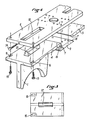
- central cores 1 and 2 which each support an assembly constituted by the motor device and the cutters which for simplicity, have not been shown in the drawing.
- the strawberries are constituted by two half-drums provided with teeth at their periphery which are rotated around the axes 3 by a motor device.
- Each core 1,2 is provided at its upper part with a horizontal sole 4,5 which allows the fixing of the engine block to the lower part of the milling apparatus, which is constituted in the embodiment described by a plate steel bottom 6.
- the ends of the flanges 4 and 5 which are directed towards the center of the device each have a bevel 7 which engages against a stop 8 of corresponding shape made on a support plate 9 which is attached to the bottom of the bottom plate 6.
- the shape of the surfaces 7 and 8 is such that when a sole plate 4.5 is pushed in the direction of the center of the apparatus, its inner edge is wedged against the support plate while being strongly applied against the bottom plate 6.
- the bottom plate 6 which constitutes the lower part of the milling apparatus has two longitudinal openings 10 and 11 inside which engage bosses 12 and 13 of elongated shape which are produced on the upper surface of the soles in the axis of webs 1 and 2.
- a bolt 14 which is engaged in a horizontal tapped hole, so that the end of the bolt 14 comes to bear on the side of the boss 12,13 to push the block corresponding motor towards the center of the device.
- the bolt 14 is then tightened, which pushes the engine block towards the center in such a way that the internal end of the sole plate 4.5 is jammed by the action of the inclined surfaces 7.8 of the support plate 9. .
- FIG. 4 is a perspective view corresponding to FIGS. 1 to 3.
Landscapes
- Engineering & Computer Science (AREA)
- Mining & Mineral Resources (AREA)
- Civil Engineering (AREA)
- Structural Engineering (AREA)
- General Engineering & Computer Science (AREA)
- General Life Sciences & Earth Sciences (AREA)
- Paleontology (AREA)
- Life Sciences & Earth Sciences (AREA)
- Mechanical Engineering (AREA)
- Cylinder Crankcases Of Internal Combustion Engines (AREA)
- Pit Excavations, Shoring, Fill Or Stabilisation Of Slopes (AREA)
- Component Parts Of Construction Machinery (AREA)
- Motor Or Generator Frames (AREA)
- Processing Of Stones Or Stones Resemblance Materials (AREA)
- Earth Drilling (AREA)
Priority Applications (1)
| Application Number | Priority Date | Filing Date | Title |
|---|---|---|---|
| AT89403175T ATE72854T1 (de) | 1988-11-18 | 1989-11-17 | Befestigungseinrichtung der betriebseinheiten einer fraesvorrichtung zum ausgraben von erdgraeben. |
Applications Claiming Priority (2)
| Application Number | Priority Date | Filing Date | Title |
|---|---|---|---|
| FR8815022A FR2639419B1 (fr) | 1988-11-18 | 1988-11-18 | Dispositif de fixation des blocs-moteurs d'un appareil de fraisage pour creuser des tranchees dans le sol |
| FR8815022 | 1988-11-18 |
Publications (2)
| Publication Number | Publication Date |
|---|---|
| EP0369890A1 true EP0369890A1 (de) | 1990-05-23 |
| EP0369890B1 EP0369890B1 (de) | 1992-02-26 |
Family
ID=9371977
Family Applications (1)
| Application Number | Title | Priority Date | Filing Date |
|---|---|---|---|
| EP89403175A Expired - Lifetime EP0369890B1 (de) | 1988-11-18 | 1989-11-17 | Befestigungseinrichtung der Betriebseinheiten einer Fräsvorrichtung zum Ausgraben von Erdgräben |
Country Status (13)
| Country | Link |
|---|---|
| US (1) | US4989824A (de) |
| EP (1) | EP0369890B1 (de) |
| JP (1) | JPH0321722A (de) |
| AR (1) | AR241057A1 (de) |
| AT (1) | ATE72854T1 (de) |
| CA (1) | CA2003266A1 (de) |
| CY (1) | CY1713A (de) |
| DE (2) | DE369890T1 (de) |
| ES (1) | ES2015857T3 (de) |
| FR (1) | FR2639419B1 (de) |
| HK (1) | HK88593A (de) |
| RU (1) | RU1838514C (de) |
| SG (1) | SG48393G (de) |
Citations (2)
| Publication number | Priority date | Publication date | Assignee | Title |
|---|---|---|---|---|
| GB2127721A (en) * | 1982-10-06 | 1984-04-18 | Hilti Ag | Upright drilling tools |
| EP0249555A1 (de) * | 1986-06-11 | 1987-12-16 | SOLETANCHE Société Anonyme dite: | Motorpumpe für Fräsgerät zum Ausheben von Gräben im Boden |
Family Cites Families (4)
| Publication number | Priority date | Publication date | Assignee | Title |
|---|---|---|---|---|
| FR1056643A (fr) * | 1952-05-16 | 1954-03-01 | Ragonot Ets | Dispositif de fixation pour moteurs électriques |
| US2885165A (en) * | 1954-11-12 | 1959-05-05 | Clayton Manufacturing Co | Engine support |
| FR2211027A5 (de) * | 1972-12-14 | 1974-07-12 | Soletanche | |
| US4085914A (en) * | 1976-03-09 | 1978-04-25 | General Electric Company | Dynamoelectric machine mounting assembly |
-
1988
- 1988-11-18 FR FR8815022A patent/FR2639419B1/fr not_active Expired - Lifetime
-
1989
- 1989-11-17 US US07/438,722 patent/US4989824A/en not_active Expired - Fee Related
- 1989-11-17 JP JP1299485A patent/JPH0321722A/ja active Granted
- 1989-11-17 DE DE198989403175T patent/DE369890T1/de active Pending
- 1989-11-17 CA CA002003266A patent/CA2003266A1/fr not_active Abandoned
- 1989-11-17 AR AR315474A patent/AR241057A1/es active
- 1989-11-17 EP EP89403175A patent/EP0369890B1/de not_active Expired - Lifetime
- 1989-11-17 RU SU894742489A patent/RU1838514C/ru active
- 1989-11-17 DE DE8989403175T patent/DE68900875D1/de not_active Expired - Fee Related
- 1989-11-17 AT AT89403175T patent/ATE72854T1/de not_active IP Right Cessation
- 1989-11-17 ES ES198989403175T patent/ES2015857T3/es not_active Expired - Lifetime
-
1993
- 1993-04-16 SG SG48393A patent/SG48393G/en unknown
- 1993-08-26 HK HK885/93A patent/HK88593A/xx unknown
-
1994
- 1994-05-06 CY CY171394A patent/CY1713A/xx unknown
Patent Citations (2)
| Publication number | Priority date | Publication date | Assignee | Title |
|---|---|---|---|---|
| GB2127721A (en) * | 1982-10-06 | 1984-04-18 | Hilti Ag | Upright drilling tools |
| EP0249555A1 (de) * | 1986-06-11 | 1987-12-16 | SOLETANCHE Société Anonyme dite: | Motorpumpe für Fräsgerät zum Ausheben von Gräben im Boden |
Also Published As
| Publication number | Publication date |
|---|---|
| EP0369890B1 (de) | 1992-02-26 |
| ES2015857T3 (es) | 1992-08-16 |
| AR241057A2 (es) | 1991-04-30 |
| JPH0321722A (ja) | 1991-01-30 |
| CY1713A (en) | 1994-05-06 |
| JPH0575852B2 (de) | 1993-10-21 |
| HK88593A (en) | 1993-09-03 |
| FR2639419B1 (fr) | 1991-03-22 |
| AR241057A1 (es) | 1991-04-30 |
| ES2015857A4 (es) | 1990-09-16 |
| ATE72854T1 (de) | 1992-03-15 |
| US4989824A (en) | 1991-02-05 |
| RU1838514C (ru) | 1993-08-30 |
| FR2639419A1 (fr) | 1990-05-25 |
| DE68900875D1 (de) | 1992-04-02 |
| DE369890T1 (de) | 1990-11-29 |
| SG48393G (en) | 1993-07-09 |
| CA2003266A1 (fr) | 1990-05-18 |
Similar Documents
| Publication | Publication Date | Title |
|---|---|---|
| EP0083289B1 (de) | Rotorrad eines Turbostrahltriebwerkes mit einer Vorrichtung zum axialen und radialen Befesten der Rotorschaufeln am Rotorrad | |
| EP0311535B1 (de) | Richtbank für die Montage, Überwachung und Reparatur, insbesondere von Karrosserien von Kraftfahrzeugen | |
| EP1221000B1 (de) | Spannvorrichtung in riemen-, ketten oder seilgetrieben zur übertragung der rotationsbewegung | |
| EP2594693B1 (de) | Vorrichtung zur Höhenregulierung einer Verschalung für Betonplatten | |
| EP0369890B1 (de) | Befestigungseinrichtung der Betriebseinheiten einer Fräsvorrichtung zum Ausgraben von Erdgräben | |
| FR3045690A1 (fr) | Dispositif d'assemblage et de fixation destine a assembler et fixer deux banches juxtaposees | |
| FR2828349A1 (fr) | Machine electrique tournante telle qu'un alternateur, notamment pour vehicule automobile, adaptable a differents types de moteurs de vehicule automobile | |
| FR2919642A1 (fr) | Dispositif de support d'un garde-corps. | |
| EP2112734B1 (de) | Elektrogerät zum Aufsetzen auf ein Einbaugehäuse | |
| EP0299871B1 (de) | Fräsvorrichtung zum Ausheben von Gräben im Boden | |
| EP1147834B1 (de) | Stanzvorrichtung | |
| FR2781837A1 (fr) | Dispositif de montage pour moteur de volet roulant | |
| BE1014582A3 (fr) | Chariot monte sur un bati et bati pour un tel chariot. | |
| FR3084162A1 (fr) | Montage d'essai, et machine de test en fatigue vibratoire. | |
| EP1450218B1 (de) | Vorrichtung und Verfahren für die Festlegung eines Kalibers auf einem Gehäusering | |
| FR2468872A1 (fr) | Instrument de mesure pour controler les dimensions geometriques lineaires de pieces mecaniques | |
| FR3068091A1 (fr) | Systeme de fixation a tenons pourvus d'appendices decales angulairement | |
| FR2606390A1 (fr) | Entrainement d'ascenseur a engrenage et vis sans fin et procede d'assemblage | |
| FR2478258A1 (fr) | Dispositif de fixation d'un support d'appareil sur un element porteur fixe | |
| WO2001014647A1 (fr) | Dispositif de liaison stable du type tripode, interpose entre un receptacle et un couvercle, et ensemble ainsi constitue | |
| EP0598659A1 (de) | Mechanismus zur Verbindung und Verriegelung einer Konsole eines Rolladens | |
| FR2562457A1 (fr) | Dispositif de montage pour meules | |
| FR2715978A1 (fr) | Dispositif d'accouplemeent de portions d'axe ou d'arbre et dispositif de montage comprenant de tels dispositifs d'accouplement. | |
| EP0849479A1 (de) | Ankervorrichtung zur einfachen Anbringung eines Gitterrosts | |
| EP1186837A1 (de) | Vorrichtung zur Wandbefestigung eines Heizkörpers und Verfahren zur dessen Befestigung |
Legal Events
| Date | Code | Title | Description |
|---|---|---|---|
| PUAI | Public reference made under article 153(3) epc to a published international application that has entered the european phase |
Free format text: ORIGINAL CODE: 0009012 |
|
| AK | Designated contracting states |
Kind code of ref document: A1 Designated state(s): AT BE CH DE ES GB IT LI |
|
| ITCL | It: translation for ep claims filed |
Representative=s name: MODIANO & ASSOCIATI S.R.L. |
|
| TCAT | At: translation of patent claims filed | ||
| 17P | Request for examination filed |
Effective date: 19900723 |
|
| GBC | Gb: translation of claims filed (gb section 78(7)/1977) | ||
| 17Q | First examination report despatched |
Effective date: 19901008 |
|
| DET | De: translation of patent claims | ||
| GRAA | (expected) grant |
Free format text: ORIGINAL CODE: 0009210 |
|
| AK | Designated contracting states |
Kind code of ref document: B1 Designated state(s): AT BE CH DE ES GB IT LI |
|
| REF | Corresponds to: |
Ref document number: 72854 Country of ref document: AT Date of ref document: 19920315 Kind code of ref document: T |
|
| REF | Corresponds to: |
Ref document number: 68900875 Country of ref document: DE Date of ref document: 19920402 |
|
| ITF | It: translation for a ep patent filed |
Owner name: MODIANO & ASSOCIATI S.R.L. |
|
| GBT | Gb: translation of ep patent filed (gb section 77(6)(a)/1977) | ||
| REG | Reference to a national code |
Ref country code: ES Ref legal event code: FG2A Ref document number: 2015857 Country of ref document: ES Kind code of ref document: T3 |
|
| PGFP | Annual fee paid to national office [announced via postgrant information from national office to epo] |
Ref country code: ES Payment date: 19921016 Year of fee payment: 4 |
|
| PGFP | Annual fee paid to national office [announced via postgrant information from national office to epo] |
Ref country code: AT Payment date: 19921023 Year of fee payment: 4 |
|
| PGFP | Annual fee paid to national office [announced via postgrant information from national office to epo] |
Ref country code: CH Payment date: 19921124 Year of fee payment: 4 |
|
| PGFP | Annual fee paid to national office [announced via postgrant information from national office to epo] |
Ref country code: BE Payment date: 19921208 Year of fee payment: 4 |
|
| PLBE | No opposition filed within time limit |
Free format text: ORIGINAL CODE: 0009261 |
|
| STAA | Information on the status of an ep patent application or granted ep patent |
Free format text: STATUS: NO OPPOSITION FILED WITHIN TIME LIMIT |
|
| 26N | No opposition filed | ||
| PG25 | Lapsed in a contracting state [announced via postgrant information from national office to epo] |
Ref country code: GB Effective date: 19931117 Ref country code: AT Effective date: 19931117 |
|
| PG25 | Lapsed in a contracting state [announced via postgrant information from national office to epo] |
Ref country code: ES Free format text: LAPSE BECAUSE OF EXPIRATION OF PROTECTION Effective date: 19931118 |
|
| PG25 | Lapsed in a contracting state [announced via postgrant information from national office to epo] |
Ref country code: LI Effective date: 19931130 Ref country code: CH Effective date: 19931130 Ref country code: BE Effective date: 19931130 |
|
| BERE | Be: lapsed |
Owner name: SOLETANCHE Effective date: 19931130 |
|
| GBPC | Gb: european patent ceased through non-payment of renewal fee |
Effective date: 19931117 |
|
| REG | Reference to a national code |
Ref country code: CH Ref legal event code: PL |
|
| PGFP | Annual fee paid to national office [announced via postgrant information from national office to epo] |
Ref country code: DE Payment date: 19991115 Year of fee payment: 11 |
|
| REG | Reference to a national code |
Ref country code: ES Ref legal event code: FD2A Effective date: 20010301 |
|
| PG25 | Lapsed in a contracting state [announced via postgrant information from national office to epo] |
Ref country code: DE Free format text: LAPSE BECAUSE OF NON-PAYMENT OF DUE FEES Effective date: 20010801 |
|
| PG25 | Lapsed in a contracting state [announced via postgrant information from national office to epo] |
Ref country code: IT Free format text: LAPSE BECAUSE OF NON-PAYMENT OF DUE FEES;WARNING: LAPSES OF ITALIAN PATENTS WITH EFFECTIVE DATE BEFORE 2007 MAY HAVE OCCURRED AT ANY TIME BEFORE 2007. THE CORRECT EFFECTIVE DATE MAY BE DIFFERENT FROM THE ONE RECORDED. Effective date: 20051117 |