EP0368843B1 - Ausgabevorrichtung - Google Patents
Ausgabevorrichtung Download PDFInfo
- Publication number
- EP0368843B1 EP0368843B1 EP87903721A EP87903721A EP0368843B1 EP 0368843 B1 EP0368843 B1 EP 0368843B1 EP 87903721 A EP87903721 A EP 87903721A EP 87903721 A EP87903721 A EP 87903721A EP 0368843 B1 EP0368843 B1 EP 0368843B1
- Authority
- EP
- European Patent Office
- Prior art keywords
- ice
- location
- chamber
- baffle
- housing
- Prior art date
- Legal status (The legal status is an assumption and is not a legal conclusion. Google has not performed a legal analysis and makes no representation as to the accuracy of the status listed.)
- Expired - Lifetime
Links
Images


Classifications
-
- A—HUMAN NECESSITIES
- A47—FURNITURE; DOMESTIC ARTICLES OR APPLIANCES; COFFEE MILLS; SPICE MILLS; SUCTION CLEANERS IN GENERAL
- A47F—SPECIAL FURNITURE, FITTINGS, OR ACCESSORIES FOR SHOPS, STOREHOUSES, BARS, RESTAURANTS OR THE LIKE; PAYING COUNTERS
- A47F1/00—Racks for dispensing merchandise; Containers for dispensing merchandise
- A47F1/02—Racks for dispensing merchandise; Containers for dispensing merchandise for granulated or powdered materials, i.e. bulk materials
- A47F1/03—Dispensing means, e.g. with buttons or handles
-
- B—PERFORMING OPERATIONS; TRANSPORTING
- B01—PHYSICAL OR CHEMICAL PROCESSES OR APPARATUS IN GENERAL
- B01F—MIXING, e.g. DISSOLVING, EMULSIFYING OR DISPERSING
- B01F31/00—Mixers with shaking, oscillating, or vibrating mechanisms
- B01F31/80—Mixing by means of high-frequency vibrations above one kHz, e.g. ultrasonic vibrations
- B01F31/85—Mixing by means of high-frequency vibrations above one kHz, e.g. ultrasonic vibrations with a vibrating element inside the receptacle
-
- A—HUMAN NECESSITIES
- A47—FURNITURE; DOMESTIC ARTICLES OR APPLIANCES; COFFEE MILLS; SPICE MILLS; SUCTION CLEANERS IN GENERAL
- A47G—HOUSEHOLD OR TABLE EQUIPMENT
- A47G19/00—Table service
- A47G19/30—Other containers or devices used as table equipment
- A47G19/32—Food containers with dispensing devices for bread, rolls, sugar, or the like; Food containers with movable covers
-
- F—MECHANICAL ENGINEERING; LIGHTING; HEATING; WEAPONS; BLASTING
- F25—REFRIGERATION OR COOLING; COMBINED HEATING AND REFRIGERATION SYSTEMS; HEAT PUMP SYSTEMS; MANUFACTURE OR STORAGE OF ICE; LIQUEFACTION SOLIDIFICATION OF GASES
- F25C—PRODUCING, WORKING OR HANDLING ICE
- F25C5/00—Working or handling ice
- F25C5/20—Distributing ice
- F25C5/24—Distributing ice for storing bins
Definitions
- This invention relates to a dispenser for dispensing pieces of ice.
- GB 2134500A discloses an ice dispensing device having the bottom wall of an ice container inclined towards the lower part of the run of an endless conveyor which is constrained to move in a vertical plane between supports and guide plates. The conveyor picks up the ice pieces and delivers them to a chute.
- FR 2586232A1 discloses a sugar dispenser having an inclined discharge chute and a spring-loaded stopper. Normally the stopper partly blocks the chute outlet so that a piece of sugar is held at the end of the chute. When the stopper is depressed and the spring compressed, the piece exits and the stopper returns to its initial position, blocking the next piece of sugar.
- FR 2386790A1 discloses an ice dispenser with a motorised rotary mechanism for dislodging ice into a chute.
- the chute has a spring-biased door at its outlet.
- CH 579894A discloses an ice dispenser having a chute disposed vertically below an ice reservoir.
- the chute outlet either has a moon-shaped ball joint or an ejector device located therein to enable ice to be dispensed.
- an ice dispenser comprising a housing defining a reservoir and a chamber beneath the reservoir and in communication therewith by a slot dimensioned to allow passage of pieces of ice, an outlet from the chamber, a dispensing structure movable within the chamber between a first location wherein said structure communicates with the chamber to receive ice therefrom, and a second location wherein said structure communicates with the outlet to discharge ice therethrough, movement of the dispensing structure from the first location to the second location causing a piece of ice received in the chamber to be dispensed from the outlet, the first location being lower than the second location, a baffle dividing the reservoir and chamber the chamber having an inclined floor thereto and the dispensing structure including a platform which, in the said first location, is contiguous with said floor, a chute extending downwardly from the housing and on which the dispensing structure is slidably mounted, and manually engageable means cooperatively engaged with the dispensing structure and disposed outwardly of the chute, said manually engageable means serving
- the dispensing structure can be movable vertically between the first and second locations.
- the dispensing structure can also be movable in an inclined direction between said locations.
- Agitating means may be provided to agitate pieces of ice in the housing, the agitating means being operable on said baffle.
- the baffle also serves to support pieces of ice and partially with the housing define said slot so that single pieces or layers of pieces of ice pass sequentially to the dispensing structure.
- the baffle may be pivoted and preferably comprises a pivoted flap.
- the baffle may be arranged to be agitated by a manually actuated member located outside the housing. Alternatively the baffle may be agitated automatically as a piece of ice is dispensed.
- the dispensing means may be arranged on upward movement to engage the baffle to impart movement thereto and thus to pieces of ice supported by the baffle.
- the housing may include a drainage chute within which said structure is guided and movable between the first and second locations.
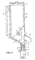
- an ice dispenser 10 for use in dispensing pieces 11 of ice, comprises a hollow open-topped housing 9 with front and rear walls 12,13 side walls 14,15 and a removable lid 16.
- the walls 13,14,15 have inwardly inclined lower portions 13 a , 14 a , 15 a respectively, which lead to the top of a drain chute 17 which terminates at its lower end in a drainage outlet 18.
- An opening 20 is provided in front wall 12 in alignment with and above the chute 17.
- a delivery or dispensing structure 21 is mounted in the chute 17 for up and down sliding movement therein, delivery structure 21 having front and rear walls 22, 23 and side walls, 24, 25 close to the respective walls of the chute 17.
- An operating knob 26 extends outwardly from structure 21 to engage an upright slot provided in wall 12 below and in alignment with the outlet 20, structure 21 being movable axially of the chute by sliding movement of the knob in the said slot.
- the front wall 22 of the delivery structure 21 is extended upwardly at 27, an aperture 28 of generally similar shape to the opening 20 being provided in the extended portion 27.
- a ledge 29 extends inwardly and upwardly of the chute from the lower edge of aperture 28, said ledge, in the down position of the structure, forming a continuation of the wall 13 a as shown in full line in Fig. 2.
- the upper edge of the aperture 28 has an inward lip 30.
- a baffle in the form of a flat flap 31 is pivotally supported within the housing 9 on a cross bar 32, the upper end of wall 27 on the delivery structure 21 being slidably guided between the wall 12 and the bar 32 (Fig. 1).
- the space above the baffle forms an ice reservoir and the space below forms a dispensing chamber.
- baffle 31 pivotally supports a bifurcated element 33 having a forward edge 34 which rests on the lip 30 and an arm 33 a which can engage baffle 31 beneath hinge 31 a .
- the pieces of ice are supported in the housing on the baffle 31 and some pass through the slot 35 between the free edge 36 of the baffle 31 and the rear wall 13. As the sides of the baffle lie close to side walls 14,15 the pieces of ice pass essentially as a single layer through the slot defined between edge 36 and the housing wall.
- the knob 26 and thus the delivery structure 21 is moved upwards so that the leading piece of ice 40, which piece is supported by the ledge 29 is lifted to a position adjacent the opening 20, to be dispensed through aligned openings 28, 20 under gravity.
- baffle is pivoted is variable according to the rest position of the edge 34 of element 33. As shown dotted at 34 a , this can be at the level of the top of opening 20 for a reduced pivoting of the baffle.
- Bifurcated element 33 may of course take other forms.
- knob 26 Only one hand is needed to dispense the ice, leaving the other hand free to hold a glass or other container to receive the ice dispensed through the opening 20. However, if preferred the hand which grips and moves knob 26 can also hold the glass into which the ice piece is to be dispensed. Alternatively, the knob 26 may be raised by engagement of the rim of a glass. A front deflector 50 can direct the piece downwards if necessary.
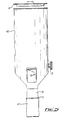
- a housing 60 having a lid 61 is formed with a cavity wall 62 to reduce heat losses.
- Clips 63 serve to mount the housing upon a wall mountable fixing plate 64.
- the interior of the housing 60 defines a receptacle for pieces of ice.
- the lower part of the receptacle 65 slopes towards a dispensing structure 66, 67, 69, 71.
- the dispensing structure comprises a platform 66 arranged, in its lowermost position, in alignment with the lower surface 65 of the housing.
- the platform 66 is secured to a rod 69 by which it is guidably supported in an upwardly extending plain bearing 68 for vertical movement relative to a support 70.
- the support 70 incorporates a drainage tube 72.
- a cup-shaped actuating member 67, attached to the lower end of rod 69 is slidable relative to support 70 and has a lip 71 which may be engaged by the rim of a user's glass or by a user's hand.
- the dispensing structure is movable between a first, lower position, as shown in full line, wherein the platform 66 is aligned with the housing surface 65 and a second, upper position shown in chain dot wherein the platform 66' is aligned with an outlet 73.
- a closure plate 74 integral with the platform 66 masks the outlet 73 when the dispensing structure is in the lower position.
- a delivery spout 80 is provided in register with outlet 73.
- a baffle 76 pivotally secured to the housing, defines a slot 77 between the lower edge of the baffle and the opposed wall of the housing, such slot being dimensioned to allow a single row of pieces of ice to pass to the lower surface 65 and thence to platform 66.
- a square or otherwise non-circular cross sectioned member 78 rotatable by means of a knob 79 on the exterior of the housing 60 is disposed below the baffle so that the latter rests thereupon. Rotation of the knob 79 causes upward and downward oscillation of the baffle about the pivot axis thereof and thus facilitate passage of pieces of ice to the lower parts of the housing, for example, by dislodging any jams which might occur, and the delivery of pieces of ice to the platform 66.
- the baffle agitating means such as a flap 31 or 76 can be connected to the dispense mechanism to ensure agitation of the store of ice each time the dispenser is actuated. Such connection can be by means of a push-rod, lever or the like.
Landscapes
- Engineering & Computer Science (AREA)
- Food Science & Technology (AREA)
- Chemical & Material Sciences (AREA)
- Chemical Kinetics & Catalysis (AREA)
- Physics & Mathematics (AREA)
- Mechanical Engineering (AREA)
- Thermal Sciences (AREA)
- General Engineering & Computer Science (AREA)
- Devices For Dispensing Beverages (AREA)
Claims (9)
- Eis-Ausgabevorrichtung (10), umfassend ein Gehäuse (9, 60), das einen Behälter und eine Kammer unterhalb des Behälters und damit in Verbindung durch einen Schlitz abgrenzt, der bemessen ist, um das Durchtreten von Eisstücken zu gestatten, einen Auslaß aus der Kammer (20, 73), eine Ausgabeanordnung (21, 66, 67, 69, 71), die in der Kammer zwischen einer ersten Stelle, bei der die Anordnung mit der Kammer in Verbindung steht, um von dort Eis aufzunehmen und einer zweiten Stelle beweglich ist, bei der die Anordnung mit dem Auslaß (20, 73) in Verbindung steht, um dort hindurch Eis auszugeben, wobei eine Bewegung der Ausgabeanordnung (21, 66, 67, 69, 71) von der ersten Stelle zur zweiten Stelle bewirkt, daß ein in der Kammer aufgenommenes Eisstück 40 aus dem Auslaß (20, 73) ausgegeben wird, wobei die erste Stelle tiefer als die zweite Stelle ist, eine Ablenkplatte (31, 76), die den Behälter und die Kammer teilt, wobei die Kammer einen dazu schräg verlaufenden Boden (13a, 65) aufweist und die Ausgabeanordnung (21, 66, 67, 69, 71) eine Rampenplatte (29, 66) enthält, die an der ersten Stelle mit dem Boden (13a, 65) benachbart ist, einen Auslauf (17, 70), der sich vom Gehäuse (9, 60) nach unten erstreckt und auf dem die Ausgabeanordnung (21, 66, 67, 69, 71) verschiebbar angebracht ist, und eine von Hand in Eingriff bringbare Einrichtung (26, 71), die mit der Ausgabeanordnung mitwirkend in Eingriff steht und außerhalb des Auslaufs (17, 70) angeordnet ist, wobei die von Hand in Eingriff bringbare Einrichtung (26, 71) dazu dient, bei Betätigung nach oben die Ausgabeanordnung von der ersten zur zweiten Stelle zu bewegen.
- Eis-Ausgabevorrichtung nach Anspruch 1, bei der der Auslaß (20, 73) mit einem sich nach außen und nach unten erstreckenden Ausgabe-Ausgußteil (50, 80) in Verbindung steht.
- Eis-Ausgabevorrichtung nach Anspruch 1 oder 2, bei der die Rampenplatte (29, 66) entsprechend dem schräg verlaufenden Boden (13a, 65) der Kammer schräg verlaufend ist.
- Eis-Ausgabevorrichtung nach Anspruch 1, 2 oder 3, bei der die Ablenkplatte (31, 76) eine bewegliche Klappe (31, 76) umfaßt.
- Eis-Ausgabevorrichtung nach einem beliebigen vorhergehenden Anspruch, weiter enthaltend eine Schüttelvorrichtung (33, 78), die zum Hin- und Herbewegen von Eisstücken im Gehäuse angeordnet ist.
- Eis-Ausgabevorrichtung nach Anspruch 5, wenn abhängig vom Anspruch 4, bei der die Schütteleinrichtung (33, 78) in zusammenwirkender Beziehung mit der Ablenkplatte (31, 76) angeordnet ist, um eine Verstellung der Ablenkplatte bei Betätigung der Schütteleinrichtung zu bewirken.
- Eis-Ausgabevorrichtung nach Anspruch 6, bei der die Schütteleinrichtung (33, 78) ein außerhalb des Gehäuses (79) angeordnetes von Hand betätigbares Element enthält.
- Eis-Ausgabevorrichtung nach Anspruch 4 oder nach einem beliebigen der Ansprüche 6 bis 7, wenn davon abhängig, bei der die Ausgabeanordnung (21, 66, 67, 69, 71) bei Aufwärtsbewegung angeordnet ist, mit einer Ablenkplatte (31, 76) in Eingriff zu treten, um dorthin Bewegung zu übertragen.
- Eis-Ausgabevorrichtung nach einem beliebigen der Ansprüche 4 bis 8, bei der die Ausgabeanordnung eine an einer Stange (69) angebrachte Rampenplatte (66), wobei die Stange (69) in einem Gleitlager (68) im Auslauf (70) beweglich ist, und ein von Hand in Eingriff bringbares Schalenteil (67) enthält, das mit der Stange (69) verbunden und angeordnet ist, um sich über der Außenseite des Auslaufs (70) bei Ausgabe eines Eisstücks zu verschieben.
Applications Claiming Priority (2)
| Application Number | Priority Date | Filing Date | Title |
|---|---|---|---|
| GB868606427A GB8606427D0 (en) | 1986-03-15 | 1986-03-15 | Dispensers |
| PCT/GB1987/000392 WO1988009636A1 (en) | 1986-03-15 | 1987-06-08 | Dispensers |
Publications (2)
| Publication Number | Publication Date |
|---|---|
| EP0368843A1 EP0368843A1 (de) | 1990-05-23 |
| EP0368843B1 true EP0368843B1 (de) | 1993-08-25 |
Family
ID=10610430
Family Applications (1)
| Application Number | Title | Priority Date | Filing Date |
|---|---|---|---|
| EP87903721A Expired - Lifetime EP0368843B1 (de) | 1986-03-15 | 1987-06-08 | Ausgabevorrichtung |
Country Status (7)
| Country | Link |
|---|---|
| US (1) | US4913315A (de) |
| EP (1) | EP0368843B1 (de) |
| JP (1) | JPH02503819A (de) |
| AU (1) | AU7482187A (de) |
| DE (1) | DE3787173T2 (de) |
| GB (2) | GB8606427D0 (de) |
| WO (1) | WO1988009636A1 (de) |
Cited By (1)
| Publication number | Priority date | Publication date | Assignee | Title |
|---|---|---|---|---|
| CN109642764A (zh) * | 2016-07-15 | 2019-04-16 | 真实制造有限公司 | 用于立式喷射型制冰机的排冰装置 |
Families Citing this family (25)
| Publication number | Priority date | Publication date | Assignee | Title |
|---|---|---|---|---|
| AU619020B2 (en) * | 1988-10-31 | 1992-01-16 | Fmc Corporation | Fruit hopper for single head juice extractor |
| US5054654A (en) * | 1989-11-14 | 1991-10-08 | Schroeder Alfred A | Combination ice and chilled beverage dispenser |
| GB2241696A (en) * | 1990-03-08 | 1991-09-11 | Rockski Limited | Solids dispenser, e.g. for ice cubes |
| US5429269A (en) * | 1992-05-04 | 1995-07-04 | Mejias; Tomas B. | Ice cube containing and dispensing device |
| ES2044782B1 (es) * | 1992-05-04 | 1994-11-16 | Mejias Tomas Barba | Aparato contenedor y dosificador de cubitos de hielo. |
| KR19980028743A (ko) * | 1996-10-24 | 1998-07-15 | 구자홍 | 드럼세탁기의 벨트장력 조절장치 |
| CA2339219A1 (en) * | 1998-08-03 | 2000-02-17 | J. Eric Berge | Vacuum pneumatic system for conveyance of ice |
| US6827529B1 (en) | 1998-08-03 | 2004-12-07 | Lancer Ice Link, Llc | Vacuum pneumatic system for conveyance of ice |
| US6237804B1 (en) * | 1999-05-17 | 2001-05-29 | Van Collin Peery | Pill dispensing apparatus |
| US6561691B1 (en) * | 2000-04-07 | 2003-05-13 | Tmo Enterprises Limited | Method and apparatus for the distribution of ice |
| JP3684227B2 (ja) * | 2002-12-02 | 2005-08-17 | 照明 伊藤 | 分注チップ自動供給装置 |
| US7144318B2 (en) * | 2004-08-18 | 2006-12-05 | Paokai Electronic Enterprise Co., Ltd. | Carrying disk device of coin dispenser |
| US7415815B2 (en) * | 2005-08-01 | 2008-08-26 | Conopco, Inc. | Tube dispensing magazine device and method |
| US7739879B2 (en) * | 2006-05-24 | 2010-06-22 | Hoshizaki America, Inc. | Methods and apparatus to reduce or prevent bridging in an ice storage bin |
| US8087533B2 (en) * | 2006-05-24 | 2012-01-03 | Hoshizaki America, Inc. | Systems and methods for providing a removable sliding access door for an ice storage bin |
| US7837061B2 (en) * | 2007-05-18 | 2010-11-23 | Parata Systems, Llc | Methods and apparatus for dispensing solid pharmaceutical articles |
| ES2644070T3 (es) * | 2007-07-30 | 2017-11-27 | Jennison Ice Llc | Dispositivo y método de agitación y dispensación de hielo |
| US20100294618A1 (en) * | 2007-07-30 | 2010-11-25 | Akoona, Llc | Ice Agitation and Dispensing Device and Method |
| US8464901B2 (en) | 2008-05-05 | 2013-06-18 | Parata Systems, Llc | Methods and apparatus for dispensing solid articles |
| US8827113B2 (en) * | 2008-05-30 | 2014-09-09 | Parata Systems, Llc | Methods and apparatus for dispensing solid articles |
| JP2010203742A (ja) * | 2009-03-05 | 2010-09-16 | Panasonic Corp | 冷蔵庫 |
| WO2014145444A1 (en) * | 2013-03-15 | 2014-09-18 | Pilltek Llc | Systems, methods, and apparatuses for securely dispensing one or more prescribed substances to a securely identified intended user |
| FR3017377B1 (fr) * | 2014-02-12 | 2017-01-13 | Stiplastics | Dispositif de comptage et de distribution d'objets |
| JP6398074B2 (ja) * | 2014-04-10 | 2018-10-03 | パナソニックIpマネジメント株式会社 | 部品供給装置 |
| WO2019136431A1 (en) * | 2018-01-08 | 2019-07-11 | Janesville Acoustics, a Unit of Jason Incorporated | Vacuum diverter assembly |
Family Cites Families (17)
| Publication number | Priority date | Publication date | Assignee | Title |
|---|---|---|---|---|
| US3276224A (en) * | 1966-10-04 | Ice-making machine and dispenser | ||
| US1861834A (en) * | 1930-04-07 | 1932-06-07 | Arnold R Binggeli | Article dispenser |
| US1916974A (en) * | 1931-11-16 | 1933-07-04 | Fuller | Match dispensing apparatus |
| FR794911A (fr) * | 1935-08-12 | 1936-02-28 | Distributeur pour ampoules ou objets cylindriques similaires | |
| US2244581A (en) * | 1937-09-07 | 1941-06-03 | Carl V Tardete | Vending machine |
| US2447054A (en) * | 1947-03-24 | 1948-08-17 | Cecil C Coates | Dispensing cabinet |
| US2429510A (en) * | 1947-07-21 | 1947-10-21 | William E Callison | Article dispensing machine |
| US3021035A (en) * | 1958-08-18 | 1962-02-13 | Apco Inc | Ice dispenser for beverage vending machines |
| US3913343A (en) * | 1971-06-14 | 1975-10-21 | Michael L Rowland | Sanitary ice storage and dispensing apparatus and method |
| CH579894A5 (en) * | 1973-01-12 | 1976-09-30 | Von Opel Margot | Ice cube dispenser - fitted with hand operated ejector mechanism having a pusher element |
| US3874559A (en) * | 1974-01-16 | 1975-04-01 | John J Pink | Ice dispenser for freezer-refrigerators and the like |
| CA1013719A (en) * | 1974-01-28 | 1977-07-12 | King-Seeley Thermos Co. | Ice making and vending machine |
| CA1105417A (en) * | 1977-04-04 | 1981-07-21 | Frank K. Karlovits | Ice dispenser |
| GB2097772B (en) * | 1981-04-30 | 1985-08-07 | Pritchard John Samuel | Article dispenser |
| GB2134500B (en) * | 1983-02-01 | 1986-02-12 | Anthony Shanley | Ice dispensing device |
| FR2586232B1 (fr) * | 1985-08-16 | 1987-11-20 | Sucrier 2000 | Distributeur de produits stockes en vrac et notamment des morceaux de sucre |
| US4679715A (en) * | 1985-09-06 | 1987-07-14 | Schneider Metal Manufacturing Co. | Ice cube dispensing outlet |
-
1986
- 1986-03-15 GB GB868606427A patent/GB8606427D0/en active Pending
-
1987
- 1987-01-14 GB GB8700771A patent/GB2187724B/en not_active Expired
- 1987-06-08 AU AU74821/87A patent/AU7482187A/en not_active Abandoned
- 1987-06-08 DE DE87903721T patent/DE3787173T2/de not_active Expired - Fee Related
- 1987-06-08 WO PCT/GB1987/000392 patent/WO1988009636A1/en active IP Right Grant
- 1987-06-08 JP JP87503453A patent/JPH02503819A/ja active Pending
- 1987-06-08 EP EP87903721A patent/EP0368843B1/de not_active Expired - Lifetime
-
1988
- 1988-11-23 US US07/275,690 patent/US4913315A/en not_active Expired - Fee Related
Cited By (1)
| Publication number | Priority date | Publication date | Assignee | Title |
|---|---|---|---|---|
| CN109642764A (zh) * | 2016-07-15 | 2019-04-16 | 真实制造有限公司 | 用于立式喷射型制冰机的排冰装置 |
Also Published As
| Publication number | Publication date |
|---|---|
| DE3787173T2 (de) | 1994-04-14 |
| DE3787173D1 (de) | 1993-09-30 |
| GB8700771D0 (en) | 1987-02-18 |
| EP0368843A1 (de) | 1990-05-23 |
| US4913315A (en) | 1990-04-03 |
| AU7482187A (en) | 1989-01-04 |
| WO1988009636A1 (en) | 1988-12-15 |
| GB2187724A (en) | 1987-09-16 |
| JPH02503819A (ja) | 1990-11-08 |
| GB8606427D0 (en) | 1986-04-23 |
| GB2187724B (en) | 1989-11-15 |
Similar Documents
| Publication | Publication Date | Title |
|---|---|---|
| EP0368843B1 (de) | Ausgabevorrichtung | |
| US4359935A (en) | Apparatus for cooking and dispensing food | |
| EP0593630B1 (de) | Heisse fertiggerichte ausgabeautomat unter verwendung mikrowellenofen | |
| US4562941A (en) | Bulk product dispenser | |
| US7178697B2 (en) | Agitator assisted bulk product dispenser | |
| EP0755031B1 (de) | Verkaufsautomat für pommes frites | |
| US5860564A (en) | Ice dispensing chute | |
| US5174470A (en) | Fried product dispensing apparatus | |
| US4165821A (en) | Beverage dispensing machine for mixing granular concentrate and water | |
| US4376499A (en) | Container with dispensing element | |
| US5429362A (en) | Medal dispenser for slot machine | |
| US4440322A (en) | Dispenser for nuts or the like | |
| US4948012A (en) | Dispenser for solid comestibles | |
| WO2001044762A1 (en) | Dry particulate dispenser | |
| US5884502A (en) | Apparatus and method for loading ice into a storage bin | |
| EP0077861B1 (de) | Spender-Dosiereinrichtung, insbesondere für pulverförmiges Material | |
| JP2000315280A (ja) | カップ式飲料自動販売機 | |
| US4911332A (en) | Cream and sugar dispenser | |
| US4673111A (en) | Nut dispensing machine | |
| US6293225B1 (en) | Automatic feeding device | |
| EP0950995A2 (de) | Anordnung einer Kippschale als Kundenzugang zu einem Verkaufsautomat | |
| US3613948A (en) | Sanitary sipping-straw dispenser | |
| CA1230279A (en) | Multiple chute coin mechanism | |
| US6293427B1 (en) | Beverage dispensing machine | |
| EP0286194A1 (de) | Verteiler für körnige Süssigkeiten, insbesondere zur Benutzung in Selbstbedienungsläden |
Legal Events
| Date | Code | Title | Description |
|---|---|---|---|
| PUAI | Public reference made under article 153(3) epc to a published international application that has entered the european phase |
Free format text: ORIGINAL CODE: 0009012 |
|
| 17P | Request for examination filed |
Effective date: 19891212 |
|
| AK | Designated contracting states |
Kind code of ref document: A1 Designated state(s): AT BE CH DE FR GB IT LI LU NL SE |
|
| RBV | Designated contracting states (corrected) |
Designated state(s): DE FR IT NL |
|
| 17Q | First examination report despatched |
Effective date: 19920227 |
|
| GRAA | (expected) grant |
Free format text: ORIGINAL CODE: 0009210 |
|
| AK | Designated contracting states |
Kind code of ref document: B1 Designated state(s): DE FR IT NL |
|
| REF | Corresponds to: |
Ref document number: 3787173 Country of ref document: DE Date of ref document: 19930930 |
|
| ITF | It: translation for a ep patent filed |
Owner name: BARZANO' E ZANARDO ROMA S.P.A. |
|
| ET | Fr: translation filed | ||
| ITTA | It: last paid annual fee | ||
| RAP2 | Party data changed (patent owner data changed or rights of a patent transferred) |
Owner name: R & G CONSTRUCTIONS LTD |
|
| NLT2 | Nl: modifications (of names), taken from the european patent patent bulletin |
Owner name: R & G CONSTRUCTIONS LTD TE PRESTWICH, GROOT-BRITTA |
|
| PG25 | Lapsed in a contracting state [announced via postgrant information from national office to epo] |
Ref country code: NL Effective date: 19950101 |
|
| REG | Reference to a national code |
Ref country code: FR Ref legal event code: TP |
|
| NLV4 | Nl: lapsed or anulled due to non-payment of the annual fee | ||
| PLBE | No opposition filed within time limit |
Free format text: ORIGINAL CODE: 0009261 |
|
| STAA | Information on the status of an ep patent application or granted ep patent |
Free format text: STATUS: NO OPPOSITION FILED WITHIN TIME LIMIT |
|
| 26N | No opposition filed | ||
| PGFP | Annual fee paid to national office [announced via postgrant information from national office to epo] |
Ref country code: DE Payment date: 19951228 Year of fee payment: 9 |
|
| PGFP | Annual fee paid to national office [announced via postgrant information from national office to epo] |
Ref country code: FR Payment date: 19951229 Year of fee payment: 9 |
|
| PG25 | Lapsed in a contracting state [announced via postgrant information from national office to epo] |
Ref country code: FR Effective date: 19970228 |
|
| PG25 | Lapsed in a contracting state [announced via postgrant information from national office to epo] |
Ref country code: DE Effective date: 19970402 |
|
| REG | Reference to a national code |
Ref country code: FR Ref legal event code: ST |
|
| PG25 | Lapsed in a contracting state [announced via postgrant information from national office to epo] |
Ref country code: IT Free format text: LAPSE BECAUSE OF NON-PAYMENT OF DUE FEES;WARNING: LAPSES OF ITALIAN PATENTS WITH EFFECTIVE DATE BEFORE 2007 MAY HAVE OCCURRED AT ANY TIME BEFORE 2007. THE CORRECT EFFECTIVE DATE MAY BE DIFFERENT FROM THE ONE RECORDED. Effective date: 20050608 |