EP0368843B1 - Dispensers - Google Patents
Dispensers Download PDFInfo
- Publication number
- EP0368843B1 EP0368843B1 EP87903721A EP87903721A EP0368843B1 EP 0368843 B1 EP0368843 B1 EP 0368843B1 EP 87903721 A EP87903721 A EP 87903721A EP 87903721 A EP87903721 A EP 87903721A EP 0368843 B1 EP0368843 B1 EP 0368843B1
- Authority
- EP
- European Patent Office
- Prior art keywords
- ice
- location
- chamber
- baffle
- housing
- Prior art date
- Legal status (The legal status is an assumption and is not a legal conclusion. Google has not performed a legal analysis and makes no representation as to the accuracy of the status listed.)
- Expired - Lifetime
Links
Images


Classifications
-
- A—HUMAN NECESSITIES
- A47—FURNITURE; DOMESTIC ARTICLES OR APPLIANCES; COFFEE MILLS; SPICE MILLS; SUCTION CLEANERS IN GENERAL
- A47F—SPECIAL FURNITURE, FITTINGS, OR ACCESSORIES FOR SHOPS, STOREHOUSES, BARS, RESTAURANTS OR THE LIKE; PAYING COUNTERS
- A47F1/00—Racks for dispensing merchandise; Containers for dispensing merchandise
- A47F1/02—Racks for dispensing merchandise; Containers for dispensing merchandise for granulated or powdered materials, i.e. bulk materials
- A47F1/03—Dispensing means, e.g. with buttons or handles
-
- B—PERFORMING OPERATIONS; TRANSPORTING
- B01—PHYSICAL OR CHEMICAL PROCESSES OR APPARATUS IN GENERAL
- B01F—MIXING, e.g. DISSOLVING, EMULSIFYING OR DISPERSING
- B01F31/00—Mixers with shaking, oscillating, or vibrating mechanisms
- B01F31/80—Mixing by means of high-frequency vibrations above one kHz, e.g. ultrasonic vibrations
- B01F31/85—Mixing by means of high-frequency vibrations above one kHz, e.g. ultrasonic vibrations with a vibrating element inside the receptacle
-
- A—HUMAN NECESSITIES
- A47—FURNITURE; DOMESTIC ARTICLES OR APPLIANCES; COFFEE MILLS; SPICE MILLS; SUCTION CLEANERS IN GENERAL
- A47G—HOUSEHOLD OR TABLE EQUIPMENT
- A47G19/00—Table service
- A47G19/30—Other containers or devices used as table equipment
- A47G19/32—Food containers with dispensing devices for bread, rolls, sugar, or the like; Food containers with movable covers
-
- F—MECHANICAL ENGINEERING; LIGHTING; HEATING; WEAPONS; BLASTING
- F25—REFRIGERATION OR COOLING; COMBINED HEATING AND REFRIGERATION SYSTEMS; HEAT PUMP SYSTEMS; MANUFACTURE OR STORAGE OF ICE; LIQUEFACTION SOLIDIFICATION OF GASES
- F25C—PRODUCING, WORKING OR HANDLING ICE
- F25C5/00—Working or handling ice
- F25C5/20—Distributing ice
- F25C5/24—Distributing ice for storing bins
Abstract
Description
- This invention relates to a dispenser for dispensing pieces of ice.
- GB 2134500A discloses an ice dispensing device having the bottom wall of an ice container inclined towards the lower part of the run of an endless conveyor which is constrained to move in a vertical plane between supports and guide plates. The conveyor picks up the ice pieces and delivers them to a chute.
- FR 2586232A1 discloses a sugar dispenser having an inclined discharge chute and a spring-loaded stopper. Normally the stopper partly blocks the chute outlet so that a piece of sugar is held at the end of the chute. When the stopper is depressed and the spring compressed, the piece exits and the stopper returns to its initial position, blocking the next piece of sugar.
- FR 2386790A1 discloses an ice dispenser with a motorised rotary mechanism for dislodging ice into a chute. The chute has a spring-biased door at its outlet.
- CH 579894A discloses an ice dispenser having a chute disposed vertically below an ice reservoir. The chute outlet either has a moon-shaped ball joint or an ejector device located therein to enable ice to be dispensed.
- According to the invention there is provided an ice dispenser comprising a housing defining a reservoir and a chamber beneath the reservoir and in communication therewith by a slot dimensioned to allow passage of pieces of ice, an outlet from the chamber, a dispensing structure movable within the chamber between a first location wherein said structure communicates with the chamber to receive ice therefrom, and a second location wherein said structure communicates with the outlet to discharge ice therethrough, movement of the dispensing structure from the first location to the second location causing a piece of ice received in the chamber to be dispensed from the outlet, the first location being lower than the second location, a baffle dividing the reservoir and chamber the chamber having an inclined floor thereto and the dispensing structure including a platform which, in the said first location, is contiguous with said floor, a chute extending downwardly from the housing and on which the dispensing structure is slidably mounted, and manually engageable means cooperatively engaged with the dispensing structure and disposed outwardly of the chute, said manually engageable means serving, upon operation, upwardly, to move the dispensing structure from the first to the second location.
- The dispensing structure can be movable vertically between the first and second locations. The dispensing structure can also be movable in an inclined direction between said locations.
- Agitating means may be provided to agitate pieces of ice in the housing, the agitating means being operable on said baffle. The baffle also serves to support pieces of ice and partially with the housing define said slot so that single pieces or layers of pieces of ice pass sequentially to the dispensing structure.
- The baffle may be pivoted and preferably comprises a pivoted flap.
- The baffle may be arranged to be agitated by a manually actuated member located outside the housing. Alternatively the baffle may be agitated automatically as a piece of ice is dispensed.
- The dispensing means may be arranged on upward movement to engage the baffle to impart movement thereto and thus to pieces of ice supported by the baffle.
- The housing may include a drainage chute within which said structure is guided and movable between the first and second locations.
- The invention will now be described further, by way of example only, with reference to the accompanying drawings, wherein:-
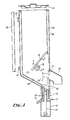
- Fig. 1 is a diagrammatic side elevation, partly broken away, of a first form of ice dispenser of the invention;
- Fig. 2. is a vertical section, drawn to a larger scale of a part of the dispenser shown in Fig. 1;
- Fig. 3 is a perspective view, drawn to a reduced scale, of the dispenser shown in Figs. 1 and 2;
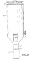
- Fig. 4 is a vertical section through a second embodiment of ice dispenser of the invention;
- Fig. 5 is a front elevation of the dispenser shown in Fig. 4;
- Fig. 6 is a plan view of the dispenser shown in Fig. 4 with the lid removed; and
- Fig. 7 is a section on line A-A of Fig.4.
- Referring now to the drawings, and particularly to Figs. 1 to 3 thereof, an
ice dispenser 10 for use in dispensing pieces 11 of ice, comprises a hollow open-topped housing 9 with front andrear walls side walls 14,15 and aremovable lid 16. Thewalls drainage outlet 18. - An
opening 20 is provided infront wall 12 in alignment with and above the chute 17. A delivery or dispensingstructure 21 is mounted in the chute 17 for up and down sliding movement therein,delivery structure 21 having front andrear walls operating knob 26 extends outwardly fromstructure 21 to engage an upright slot provided inwall 12 below and in alignment with theoutlet 20,structure 21 being movable axially of the chute by sliding movement of the knob in the said slot. Thefront wall 22 of thedelivery structure 21 is extended upwardly at 27, anaperture 28 of generally similar shape to the opening 20 being provided in the extendedportion 27. Aledge 29 extends inwardly and upwardly of the chute from the lower edge ofaperture 28, said ledge, in the down position of the structure, forming a continuation of the wall 13a as shown in full line in Fig. 2. The upper edge of theaperture 28 has aninward lip 30. - A baffle in the form of a
flat flap 31 is pivotally supported within the housing 9 on across bar 32, the upper end ofwall 27 on thedelivery structure 21 being slidably guided between thewall 12 and the bar 32 (Fig. 1). The space above the baffle forms an ice reservoir and the space below forms a dispensing chamber. - At its
underside baffle 31 pivotally supports a bifurcatedelement 33 having aforward edge 34 which rests on thelip 30 and an arm 33a which can engagebaffle 31 beneath hinge 31a. - On loading the dispenser, the pieces of ice are supported in the housing on the
baffle 31 and some pass through theslot 35 between thefree edge 36 of thebaffle 31 and therear wall 13. As the sides of the baffle lie close toside walls 14,15 the pieces of ice pass essentially as a single layer through the slot defined betweenedge 36 and the housing wall. - When it is desired to dispense a piece of ice, the
knob 26 and thus thedelivery structure 21, is moved upwards so that the leading piece ofice 40, which piece is supported by theledge 29 is lifted to a position adjacent theopening 20, to be dispensed through alignedopenings - Upward movement of
delivery structure 21lifts element 33 and causes the baffle to pivot, thereby disturbing the mass of ice above the flap and hence reduce the possibility of jamming of ice pieces in theslot 35. - The extent to which the baffle is pivoted is variable according to the rest position of the
edge 34 ofelement 33. As shown dotted at 34a, this can be at the level of the top of opening 20 for a reduced pivoting of the baffle. Bifurcatedelement 33 may of course take other forms. - Only one hand is needed to dispense the ice, leaving the other hand free to hold a glass or other container to receive the ice dispensed through the opening 20. However, if preferred the hand which grips and moves
knob 26 can also hold the glass into which the ice piece is to be dispensed. Alternatively, theknob 26 may be raised by engagement of the rim of a glass. Afront deflector 50 can direct the piece downwards if necessary. - With this device the ice pieces can be dispensed without being handled.
- In an alternative embodiment, see now Figs. 4 to 7, a
housing 60 having alid 61 is formed with acavity wall 62 to reduce heat losses.Clips 63 serve to mount the housing upon a wallmountable fixing plate 64. The interior of thehousing 60 defines a receptacle for pieces of ice. The lower part of thereceptacle 65 slopes towards adispensing structure - The dispensing structure comprises a
platform 66 arranged, in its lowermost position, in alignment with thelower surface 65 of the housing. Theplatform 66 is secured to arod 69 by which it is guidably supported in an upwardly extending plain bearing 68 for vertical movement relative to asupport 70. Thesupport 70 incorporates adrainage tube 72. A cup-shaped actuatingmember 67, attached to the lower end ofrod 69 is slidable relative to support 70 and has alip 71 which may be engaged by the rim of a user's glass or by a user's hand. In use, the dispensing structure is movable between a first, lower position, as shown in full line, wherein theplatform 66 is aligned with thehousing surface 65 and a second, upper position shown in chain dot wherein the platform 66' is aligned with anoutlet 73. Aclosure plate 74 integral with theplatform 66 masks theoutlet 73 when the dispensing structure is in the lower position. Adelivery spout 80 is provided in register withoutlet 73. - A
baffle 76, pivotally secured to the housing, defines aslot 77 between the lower edge of the baffle and the opposed wall of the housing, such slot being dimensioned to allow a single row of pieces of ice to pass to thelower surface 65 and thence toplatform 66. A square or otherwise non-circular cross sectionedmember 78, rotatable by means of aknob 79 on the exterior of thehousing 60 is disposed below the baffle so that the latter rests thereupon. Rotation of theknob 79 causes upward and downward oscillation of the baffle about the pivot axis thereof and thus facilitate passage of pieces of ice to the lower parts of the housing, for example, by dislodging any jams which might occur, and the delivery of pieces of ice to theplatform 66. - The baffle agitating means, such as a
flap
Claims (9)
- An ice dispenser (10) comprising a housing (9, 60) defining a reservoir and a chamber beneath the reservoir and in communication therewith by a slot dimensioned to allow passage of pieces of ice, an outlet from the chamber (20, 73) a dispensing structure (21, 66, 67, 69, 71) movable within the chamber between a first location wherein said structure communicates with the chamber to receive ice therefrom, and a second location wherein said structure communicates with the outlet (20, 73) to discharge ice therethrough, movement of the dispensing structure (21, 66, 67, 69, 71) from the first location to the second location causing a piece of ice (40) received in the chamber to be dispensed from the outlet (20, 73), the first location being lower than the second location, a baffle (31, 76) dividing the reservoir and chamber, the chamber having an inclined floor (13a, 65) thereto and the dispensing structure (21, 66, 67, 69, 71) including a platform (29, 66) which, in the said first location, is contiguous with said floor (13a, 65), a chute (17, 70) extending downwardly from the housing (9, 60) and on which the dispensing structure (21, 66, 67, 69, 71) is slidably mounted, and manually engageable means (26, 71) cooperatively engaged with the dispensing structure and disposed outwardly of the chute (17, 70), said manually engageable means (26, 71) serving, upon operation, upwardly, to move the dispensing structure from the first to the second location.
- An ice dispenser as claimed in claim 1, wherein the outlet (20, 73) communicates with an outwardly and downwardly extending dispense spout (50, 80).
- An ice dispenser as claimed in claim 1 or 2, wherein the platform (29, 66) is inclined in correspondence to the sloping floor (13a, 65) of the chamber.
- An ice dispenser as claimed in claim 1, 2 or 3 wherein the baffle (31, 76) comprises a movable flap (31, 76).
- An ice dispenser as claimed in any preceding claim further including agitating means (33, 78) arranged to agitate pieces of ice in the housing.
- An ice dispenser as claimed in claim 5 when dependent from claim 4, wherein the agitating means (33, 78) is arranged in cooperative relationship with the baffle (31, 76) to effect displacement of said baffle upon actuation of the agitating means.
- An ice dispenser as claimed in claim 6, wherein said agitating means (33, 78) includes a manually actuable member located outside the housing (79).
- An ice dispenser as claimed in claim 4 or in any of claims 6 to 7 when dependent therefrom, wherein the dispensing structure (21, 66, 67, 69, 71) is arranged, on upward movement, to engage a baffle (31, 76) to impart movement thereto.
- An ice dispenser as claimed in any of claims 4 to 8, wherein the dispensing structure includes a platform (66) mounted on a rod (69) the rod (69) being movable within a plain bearing (68) in the chute (70) and a manually engageable cup (67) connected to the rod (69) and arranged to slide over the exterior of the chute (70) in dispensing a piece of ice.
Applications Claiming Priority (2)
| Application Number | Priority Date | Filing Date | Title |
|---|---|---|---|
| GB868606427A GB8606427D0 (en) | 1986-03-15 | 1986-03-15 | Dispensers |
| PCT/GB1987/000392 WO1988009636A1 (en) | 1986-03-15 | 1987-06-08 | Dispensers |
Publications (2)
| Publication Number | Publication Date |
|---|---|
| EP0368843A1 EP0368843A1 (en) | 1990-05-23 |
| EP0368843B1 true EP0368843B1 (en) | 1993-08-25 |
Family
ID=10610430
Family Applications (1)
| Application Number | Title | Priority Date | Filing Date |
|---|---|---|---|
| EP87903721A Expired - Lifetime EP0368843B1 (en) | 1986-03-15 | 1987-06-08 | Dispensers |
Country Status (7)
| Country | Link |
|---|---|
| US (1) | US4913315A (en) |
| EP (1) | EP0368843B1 (en) |
| JP (1) | JPH02503819A (en) |
| AU (1) | AU7482187A (en) |
| DE (1) | DE3787173T2 (en) |
| GB (2) | GB8606427D0 (en) |
| WO (1) | WO1988009636A1 (en) |
Cited By (1)
| Publication number | Priority date | Publication date | Assignee | Title |
|---|---|---|---|---|
| CN109642764A (en) * | 2016-07-15 | 2019-04-16 | 真实制造有限公司 | Ice discharge apparatus for vertical ejection-type ice machine |
Families Citing this family (25)
| Publication number | Priority date | Publication date | Assignee | Title |
|---|---|---|---|---|
| AU619020B2 (en) * | 1988-10-31 | 1992-01-16 | Fmc Corporation | Fruit hopper for single head juice extractor |
| US5054654A (en) * | 1989-11-14 | 1991-10-08 | Schroeder Alfred A | Combination ice and chilled beverage dispenser |
| GB2241696A (en) * | 1990-03-08 | 1991-09-11 | Rockski Limited | Solids dispenser, e.g. for ice cubes |
| ES2044782B1 (en) * | 1992-05-04 | 1994-11-16 | Mejias Tomas Barba | ICE CUBE CONTAINER AND DISPENSER DEVICE. |
| EP0596082A1 (en) * | 1992-05-04 | 1994-05-11 | BARBA MEJIAS, Tomas | Apparatus for holding and proportioning ice cubes |
| KR19980028743A (en) * | 1996-10-24 | 1998-07-15 | 구자홍 | Belt tensioning device of drum washing machine |
| EP1102951A1 (en) * | 1998-08-03 | 2001-05-30 | Lancer Ice Link, L.L.C | Vacuum pneumatic system for conveyance of ice |
| US6827529B1 (en) | 1998-08-03 | 2004-12-07 | Lancer Ice Link, Llc | Vacuum pneumatic system for conveyance of ice |
| US6237804B1 (en) * | 1999-05-17 | 2001-05-29 | Van Collin Peery | Pill dispensing apparatus |
| US6561691B1 (en) * | 2000-04-07 | 2003-05-13 | Tmo Enterprises Limited | Method and apparatus for the distribution of ice |
| JP3684227B2 (en) * | 2002-12-02 | 2005-08-17 | 照明 伊藤 | Automatic dispensing tip feeder |
| US7144318B2 (en) * | 2004-08-18 | 2006-12-05 | Paokai Electronic Enterprise Co., Ltd. | Carrying disk device of coin dispenser |
| US7415815B2 (en) * | 2005-08-01 | 2008-08-26 | Conopco, Inc. | Tube dispensing magazine device and method |
| US7739879B2 (en) * | 2006-05-24 | 2010-06-22 | Hoshizaki America, Inc. | Methods and apparatus to reduce or prevent bridging in an ice storage bin |
| US8087533B2 (en) * | 2006-05-24 | 2012-01-03 | Hoshizaki America, Inc. | Systems and methods for providing a removable sliding access door for an ice storage bin |
| US7837061B2 (en) * | 2007-05-18 | 2010-11-23 | Parata Systems, Llc | Methods and apparatus for dispensing solid pharmaceutical articles |
| US20100294618A1 (en) * | 2007-07-30 | 2010-11-25 | Akoona, Llc | Ice Agitation and Dispensing Device and Method |
| US8365951B2 (en) * | 2007-07-30 | 2013-02-05 | Akoona Llc | Ice agitation and dispensing device and method |
| US8464901B2 (en) | 2008-05-05 | 2013-06-18 | Parata Systems, Llc | Methods and apparatus for dispensing solid articles |
| US8827113B2 (en) * | 2008-05-30 | 2014-09-09 | Parata Systems, Llc | Methods and apparatus for dispensing solid articles |
| JP2010203742A (en) * | 2009-03-05 | 2010-09-16 | Panasonic Corp | Refrigerator |
| US9953140B2 (en) * | 2013-03-15 | 2018-04-24 | Intent Solutions, Inc. | Systems, methods, and apparatuses for securely dispensing one or more prescribed substances to a securely identified intended user |
| FR3017377B1 (en) * | 2014-02-12 | 2017-01-13 | Stiplastics | DEVICE FOR COUNTING AND DISPENSING OBJECTS |
| JP6398074B2 (en) * | 2014-04-10 | 2018-10-03 | パナソニックIpマネジメント株式会社 | Parts supply device |
| US11072084B2 (en) * | 2018-01-08 | 2021-07-27 | Janesville Acoustics, a Unit of Jason Incorporated | Vacuum diverter assembly |
Family Cites Families (17)
| Publication number | Priority date | Publication date | Assignee | Title |
|---|---|---|---|---|
| US3276224A (en) * | 1966-10-04 | Ice-making machine and dispenser | ||
| US1861834A (en) * | 1930-04-07 | 1932-06-07 | Arnold R Binggeli | Article dispenser |
| US1916974A (en) * | 1931-11-16 | 1933-07-04 | Fuller | Match dispensing apparatus |
| FR794911A (en) * | 1935-08-12 | 1936-02-28 | Dispenser for ampoules or similar cylindrical objects | |
| US2244581A (en) * | 1937-09-07 | 1941-06-03 | Carl V Tardete | Vending machine |
| US2447054A (en) * | 1947-03-24 | 1948-08-17 | Cecil C Coates | Dispensing cabinet |
| US2429510A (en) * | 1947-07-21 | 1947-10-21 | William E Callison | Article dispensing machine |
| US3021035A (en) * | 1958-08-18 | 1962-02-13 | Apco Inc | Ice dispenser for beverage vending machines |
| US3913343A (en) * | 1971-06-14 | 1975-10-21 | Michael L Rowland | Sanitary ice storage and dispensing apparatus and method |
| CH579894A5 (en) * | 1973-01-12 | 1976-09-30 | Von Opel Margot | Ice cube dispenser - fitted with hand operated ejector mechanism having a pusher element |
| US3874559A (en) * | 1974-01-16 | 1975-04-01 | John J Pink | Ice dispenser for freezer-refrigerators and the like |
| CA1013719A (en) * | 1974-01-28 | 1977-07-12 | King-Seeley Thermos Co. | Ice making and vending machine |
| CA1105417A (en) * | 1977-04-04 | 1981-07-21 | Frank K. Karlovits | Ice dispenser |
| GB2097772B (en) * | 1981-04-30 | 1985-08-07 | Pritchard John Samuel | Article dispenser |
| GB2134500B (en) * | 1983-02-01 | 1986-02-12 | Anthony Shanley | Ice dispensing device |
| FR2586232B1 (en) * | 1985-08-16 | 1987-11-20 | Sucrier 2000 | DISTRIBUTOR OF BULK STORED PRODUCTS AND PARTICULARLY SUGAR PIECES |
| US4679715A (en) * | 1985-09-06 | 1987-07-14 | Schneider Metal Manufacturing Co. | Ice cube dispensing outlet |
-
1986
- 1986-03-15 GB GB868606427A patent/GB8606427D0/en active Pending
-
1987
- 1987-01-14 GB GB8700771A patent/GB2187724B/en not_active Expired
- 1987-06-08 AU AU74821/87A patent/AU7482187A/en not_active Abandoned
- 1987-06-08 EP EP87903721A patent/EP0368843B1/en not_active Expired - Lifetime
- 1987-06-08 JP JP87503453A patent/JPH02503819A/en active Pending
- 1987-06-08 WO PCT/GB1987/000392 patent/WO1988009636A1/en active IP Right Grant
- 1987-06-08 DE DE87903721T patent/DE3787173T2/en not_active Expired - Fee Related
-
1988
- 1988-11-23 US US07/275,690 patent/US4913315A/en not_active Expired - Fee Related
Cited By (1)
| Publication number | Priority date | Publication date | Assignee | Title |
|---|---|---|---|---|
| CN109642764A (en) * | 2016-07-15 | 2019-04-16 | 真实制造有限公司 | Ice discharge apparatus for vertical ejection-type ice machine |
Also Published As
| Publication number | Publication date |
|---|---|
| WO1988009636A1 (en) | 1988-12-15 |
| DE3787173D1 (en) | 1993-09-30 |
| GB8700771D0 (en) | 1987-02-18 |
| GB2187724B (en) | 1989-11-15 |
| JPH02503819A (en) | 1990-11-08 |
| GB8606427D0 (en) | 1986-04-23 |
| GB2187724A (en) | 1987-09-16 |
| AU7482187A (en) | 1989-01-04 |
| EP0368843A1 (en) | 1990-05-23 |
| US4913315A (en) | 1990-04-03 |
| DE3787173T2 (en) | 1994-04-14 |
Similar Documents
| Publication | Publication Date | Title |
|---|---|---|
| EP0368843B1 (en) | Dispensers | |
| US4359935A (en) | Apparatus for cooking and dispensing food | |
| EP0593630B1 (en) | Automatic hot food dispenser using microwave ovens | |
| US4562941A (en) | Bulk product dispenser | |
| US7178697B2 (en) | Agitator assisted bulk product dispenser | |
| EP0755031B1 (en) | Machine for dispensing fried potatoes | |
| US5860564A (en) | Ice dispensing chute | |
| US5174470A (en) | Fried product dispensing apparatus | |
| US4376499A (en) | Container with dispensing element | |
| US5429362A (en) | Medal dispenser for slot machine | |
| US4440322A (en) | Dispenser for nuts or the like | |
| US4948012A (en) | Dispenser for solid comestibles | |
| WO2001044762A1 (en) | Dry particulate dispenser | |
| US5884502A (en) | Apparatus and method for loading ice into a storage bin | |
| EP0077861B1 (en) | Dispensing and measuring device, especially for powdery products | |
| US4169542A (en) | Dispenser for cup holders | |
| JP2000315280A (en) | Automatic vending machine for serving beverage in cup | |
| US4911332A (en) | Cream and sugar dispenser | |
| US4673111A (en) | Nut dispensing machine | |
| EP1006786B1 (en) | Automatic feeding device | |
| EP0950995A2 (en) | Tipping tray assembly acting as a customer access vend door | |
| US3613948A (en) | Sanitary sipping-straw dispenser | |
| US6293427B1 (en) | Beverage dispensing machine | |
| EP0286194A1 (en) | Dispenser for granular sweets, particularly for use in self-service stores | |
| US6622844B2 (en) | Vending machine with improved coin box and supplemental base support for unloading access to the box |
Legal Events
| Date | Code | Title | Description |
|---|---|---|---|
| PUAI | Public reference made under article 153(3) epc to a published international application that has entered the european phase |
Free format text: ORIGINAL CODE: 0009012 |
|
| 17P | Request for examination filed |
Effective date: 19891212 |
|
| AK | Designated contracting states |
Kind code of ref document: A1 Designated state(s): AT BE CH DE FR GB IT LI LU NL SE |
|
| RBV | Designated contracting states (corrected) |
Designated state(s): DE FR IT NL |
|
| 17Q | First examination report despatched |
Effective date: 19920227 |
|
| GRAA | (expected) grant |
Free format text: ORIGINAL CODE: 0009210 |
|
| AK | Designated contracting states |
Kind code of ref document: B1 Designated state(s): DE FR IT NL |
|
| REF | Corresponds to: |
Ref document number: 3787173 Country of ref document: DE Date of ref document: 19930930 |
|
| ITF | It: translation for a ep patent filed |
Owner name: BARZANO' E ZANARDO ROMA S.P.A. |
|
| ET | Fr: translation filed | ||
| ITTA | It: last paid annual fee | ||
| RAP2 | Party data changed (patent owner data changed or rights of a patent transferred) |
Owner name: R & G CONSTRUCTIONS LTD |
|
| NLT2 | Nl: modifications (of names), taken from the european patent patent bulletin |
Owner name: R & G CONSTRUCTIONS LTD TE PRESTWICH, GROOT-BRITTA |
|
| PG25 | Lapsed in a contracting state [announced via postgrant information from national office to epo] |
Ref country code: NL Effective date: 19950101 |
|
| REG | Reference to a national code |
Ref country code: FR Ref legal event code: TP |
|
| NLV4 | Nl: lapsed or anulled due to non-payment of the annual fee | ||
| PLBE | No opposition filed within time limit |
Free format text: ORIGINAL CODE: 0009261 |
|
| STAA | Information on the status of an ep patent application or granted ep patent |
Free format text: STATUS: NO OPPOSITION FILED WITHIN TIME LIMIT |
|
| 26N | No opposition filed | ||
| PGFP | Annual fee paid to national office [announced via postgrant information from national office to epo] |
Ref country code: DE Payment date: 19951228 Year of fee payment: 9 |
|
| PGFP | Annual fee paid to national office [announced via postgrant information from national office to epo] |
Ref country code: FR Payment date: 19951229 Year of fee payment: 9 |
|
| PG25 | Lapsed in a contracting state [announced via postgrant information from national office to epo] |
Ref country code: FR Effective date: 19970228 |
|
| PG25 | Lapsed in a contracting state [announced via postgrant information from national office to epo] |
Ref country code: DE Effective date: 19970402 |
|
| REG | Reference to a national code |
Ref country code: FR Ref legal event code: ST |
|
| PG25 | Lapsed in a contracting state [announced via postgrant information from national office to epo] |
Ref country code: IT Free format text: LAPSE BECAUSE OF NON-PAYMENT OF DUE FEES;WARNING: LAPSES OF ITALIAN PATENTS WITH EFFECTIVE DATE BEFORE 2007 MAY HAVE OCCURRED AT ANY TIME BEFORE 2007. THE CORRECT EFFECTIVE DATE MAY BE DIFFERENT FROM THE ONE RECORDED. Effective date: 20050608 |