EP0368649A1 - Druckwechsel-Gastrennung - Google Patents
Druckwechsel-Gastrennung Download PDFInfo
- Publication number
- EP0368649A1 EP0368649A1 EP89311584A EP89311584A EP0368649A1 EP 0368649 A1 EP0368649 A1 EP 0368649A1 EP 89311584 A EP89311584 A EP 89311584A EP 89311584 A EP89311584 A EP 89311584A EP 0368649 A1 EP0368649 A1 EP 0368649A1
- Authority
- EP
- European Patent Office
- Prior art keywords
- bed
- diaphragm
- pressure swing
- gas
- gas separator
- Prior art date
- Legal status (The legal status is an assumption and is not a legal conclusion. Google has not performed a legal analysis and makes no representation as to the accuracy of the status listed.)
- Withdrawn
Links
Images
Classifications
-
- F—MECHANICAL ENGINEERING; LIGHTING; HEATING; WEAPONS; BLASTING
- F23—COMBUSTION APPARATUS; COMBUSTION PROCESSES
- F23C—METHODS OR APPARATUS FOR COMBUSTION USING FLUID FUEL OR SOLID FUEL SUSPENDED IN A CARRIER GAS OR AIR
- F23C15/00—Apparatus in which combustion takes place in pulses influenced by acoustic resonance in a gas mass
-
- B—PERFORMING OPERATIONS; TRANSPORTING
- B01—PHYSICAL OR CHEMICAL PROCESSES OR APPARATUS IN GENERAL
- B01D—SEPARATION
- B01D53/00—Separation of gases or vapours; Recovering vapours of volatile solvents from gases; Chemical or biological purification of waste gases, e.g. engine exhaust gases, smoke, fumes, flue gases, aerosols
- B01D53/02—Separation of gases or vapours; Recovering vapours of volatile solvents from gases; Chemical or biological purification of waste gases, e.g. engine exhaust gases, smoke, fumes, flue gases, aerosols by adsorption, e.g. preparative gas chromatography
- B01D53/04—Separation of gases or vapours; Recovering vapours of volatile solvents from gases; Chemical or biological purification of waste gases, e.g. engine exhaust gases, smoke, fumes, flue gases, aerosols by adsorption, e.g. preparative gas chromatography with stationary adsorbents
- B01D53/0407—Constructional details of adsorbing systems
-
- B—PERFORMING OPERATIONS; TRANSPORTING
- B01—PHYSICAL OR CHEMICAL PROCESSES OR APPARATUS IN GENERAL
- B01D—SEPARATION
- B01D53/00—Separation of gases or vapours; Recovering vapours of volatile solvents from gases; Chemical or biological purification of waste gases, e.g. engine exhaust gases, smoke, fumes, flue gases, aerosols
- B01D53/02—Separation of gases or vapours; Recovering vapours of volatile solvents from gases; Chemical or biological purification of waste gases, e.g. engine exhaust gases, smoke, fumes, flue gases, aerosols by adsorption, e.g. preparative gas chromatography
- B01D53/04—Separation of gases or vapours; Recovering vapours of volatile solvents from gases; Chemical or biological purification of waste gases, e.g. engine exhaust gases, smoke, fumes, flue gases, aerosols by adsorption, e.g. preparative gas chromatography with stationary adsorbents
- B01D53/047—Pressure swing adsorption
- B01D53/0473—Rapid pressure swing adsorption
-
- F—MECHANICAL ENGINEERING; LIGHTING; HEATING; WEAPONS; BLASTING
- F02—COMBUSTION ENGINES; HOT-GAS OR COMBUSTION-PRODUCT ENGINE PLANTS
- F02G—HOT GAS OR COMBUSTION-PRODUCT POSITIVE-DISPLACEMENT ENGINE PLANTS; USE OF WASTE HEAT OF COMBUSTION ENGINES; NOT OTHERWISE PROVIDED FOR
- F02G1/00—Hot gas positive-displacement engine plants
- F02G1/04—Hot gas positive-displacement engine plants of closed-cycle type
- F02G1/043—Hot gas positive-displacement engine plants of closed-cycle type the engine being operated by expansion and contraction of a mass of working gas which is heated and cooled in one of a plurality of constantly communicating expansible chambers, e.g. Stirling cycle type engines
- F02G1/0435—Hot gas positive-displacement engine plants of closed-cycle type the engine being operated by expansion and contraction of a mass of working gas which is heated and cooled in one of a plurality of constantly communicating expansible chambers, e.g. Stirling cycle type engines the engine being of the free piston type
-
- F—MECHANICAL ENGINEERING; LIGHTING; HEATING; WEAPONS; BLASTING
- F02—COMBUSTION ENGINES; HOT-GAS OR COMBUSTION-PRODUCT ENGINE PLANTS
- F02G—HOT GAS OR COMBUSTION-PRODUCT POSITIVE-DISPLACEMENT ENGINE PLANTS; USE OF WASTE HEAT OF COMBUSTION ENGINES; NOT OTHERWISE PROVIDED FOR
- F02G3/00—Combustion-product positive-displacement engine plants
-
- B—PERFORMING OPERATIONS; TRANSPORTING
- B01—PHYSICAL OR CHEMICAL PROCESSES OR APPARATUS IN GENERAL
- B01D—SEPARATION
- B01D2253/00—Adsorbents used in seperation treatment of gases and vapours
- B01D2253/10—Inorganic adsorbents
- B01D2253/106—Silica or silicates
- B01D2253/108—Zeolites
-
- B—PERFORMING OPERATIONS; TRANSPORTING
- B01—PHYSICAL OR CHEMICAL PROCESSES OR APPARATUS IN GENERAL
- B01D—SEPARATION
- B01D2253/00—Adsorbents used in seperation treatment of gases and vapours
- B01D2253/30—Physical properties of adsorbents
- B01D2253/302—Dimensions
- B01D2253/304—Linear dimensions, e.g. particle shape, diameter
-
- B—PERFORMING OPERATIONS; TRANSPORTING
- B01—PHYSICAL OR CHEMICAL PROCESSES OR APPARATUS IN GENERAL
- B01D—SEPARATION
- B01D2256/00—Main component in the product gas stream after treatment
- B01D2256/12—Oxygen
-
- B—PERFORMING OPERATIONS; TRANSPORTING
- B01—PHYSICAL OR CHEMICAL PROCESSES OR APPARATUS IN GENERAL
- B01D—SEPARATION
- B01D2257/00—Components to be removed
- B01D2257/10—Single element gases other than halogens
- B01D2257/102—Nitrogen
-
- B—PERFORMING OPERATIONS; TRANSPORTING
- B01—PHYSICAL OR CHEMICAL PROCESSES OR APPARATUS IN GENERAL
- B01D—SEPARATION
- B01D2259/00—Type of treatment
- B01D2259/40—Further details for adsorption processes and devices
- B01D2259/401—Further details for adsorption processes and devices using a single bed
-
- B—PERFORMING OPERATIONS; TRANSPORTING
- B01—PHYSICAL OR CHEMICAL PROCESSES OR APPARATUS IN GENERAL
- B01D—SEPARATION
- B01D53/00—Separation of gases or vapours; Recovering vapours of volatile solvents from gases; Chemical or biological purification of waste gases, e.g. engine exhaust gases, smoke, fumes, flue gases, aerosols
- B01D53/02—Separation of gases or vapours; Recovering vapours of volatile solvents from gases; Chemical or biological purification of waste gases, e.g. engine exhaust gases, smoke, fumes, flue gases, aerosols by adsorption, e.g. preparative gas chromatography
- B01D53/04—Separation of gases or vapours; Recovering vapours of volatile solvents from gases; Chemical or biological purification of waste gases, e.g. engine exhaust gases, smoke, fumes, flue gases, aerosols by adsorption, e.g. preparative gas chromatography with stationary adsorbents
- B01D53/0407—Constructional details of adsorbing systems
- B01D53/0446—Means for feeding or distributing gases
-
- F—MECHANICAL ENGINEERING; LIGHTING; HEATING; WEAPONS; BLASTING
- F02—COMBUSTION ENGINES; HOT-GAS OR COMBUSTION-PRODUCT ENGINE PLANTS
- F02G—HOT GAS OR COMBUSTION-PRODUCT POSITIVE-DISPLACEMENT ENGINE PLANTS; USE OF WASTE HEAT OF COMBUSTION ENGINES; NOT OTHERWISE PROVIDED FOR
- F02G2243/00—Stirling type engines having closed regenerative thermodynamic cycles with flow controlled by volume changes
- F02G2243/30—Stirling type engines having closed regenerative thermodynamic cycles with flow controlled by volume changes having their pistons and displacers each in separate cylinders
- F02G2243/50—Stirling type engines having closed regenerative thermodynamic cycles with flow controlled by volume changes having their pistons and displacers each in separate cylinders having resonance tubes
- F02G2243/52—Stirling type engines having closed regenerative thermodynamic cycles with flow controlled by volume changes having their pistons and displacers each in separate cylinders having resonance tubes acoustic
-
- Y—GENERAL TAGGING OF NEW TECHNOLOGICAL DEVELOPMENTS; GENERAL TAGGING OF CROSS-SECTIONAL TECHNOLOGIES SPANNING OVER SEVERAL SECTIONS OF THE IPC; TECHNICAL SUBJECTS COVERED BY FORMER USPC CROSS-REFERENCE ART COLLECTIONS [XRACs] AND DIGESTS
- Y02—TECHNOLOGIES OR APPLICATIONS FOR MITIGATION OR ADAPTATION AGAINST CLIMATE CHANGE
- Y02E—REDUCTION OF GREENHOUSE GAS [GHG] EMISSIONS, RELATED TO ENERGY GENERATION, TRANSMISSION OR DISTRIBUTION
- Y02E20/00—Combustion technologies with mitigation potential
- Y02E20/34—Indirect CO2mitigation, i.e. by acting on non CO2directly related matters of the process, e.g. pre-heating or heat recovery
Definitions
- Pressure swing gas separators include a bed of adsorbent material which preferentially adsorbs at least one gas from a mixture of gases.
- a pressure swing gas separator uses this preferential adsorption to preferentially remove that gas from a mixture of gases either to provide a gas mixture having a higher concentration of the preferentially adsorbed gas or a depleted gas mixture which has a lower concentration of the preferentially adsorbed gas.
- the adsorbent bed is pressurised with the gas mixture and the preferentially adsorbed component is adsorbed onto the bed until the bed is saturated with that one component of the gas mixture.
- the bed is then vented and the gas mixture depleted by the preferentially adsorbed component is discharged.
- the bed is then subjected to a reduced pressure and under these circumstances the gas adsorbed onto the bed is desorbed to produce a gas which is rich in the gas which is preferentially adsorbed.
- a pressure swing gas separator is operated with a pressure difference between its pressurised and depressurised states of less than 0.1 bar.
- the pressure swing gas separator is operated at a repetition frequency greater than one cycle per second.
- the pressure swing gas separator operates at a repetition frequency greater than 10 cycles per second and typically operates at a repetition frequency of between 50 and 200 cycles per second. Accordingly, a pressure swing gas separator in accordance with a second aspect of this invention is very much faster than the earlier proposals for rapid pressure swing adsorption by a factor of as much as one thousand.
- the pressure swing gas separator includes a combination of both the first and second aspects of this invention and, under these circumstances the high repetition frequency of its operation more than makes up for the low volume of gas produced in each cycle.
- a combination of the first and second aspects of this invention provide a good throughput of gas with only a low energy requirement.
- a pressure swing gas separator includes a bed of adsorbent material and forms part of a resonant system, the pressure swing gas separator including means operating at the resonant frequency of the resonant system to pressurise and depressurise the bed of adsorbent material so that the pressure energy of the desorbed gas mixture is substantially recovered.
- EP-A-0267727 describes and claims a gas resonance device comprising a resonance tube which expands in cross-section along its length from one end to the other, a heat source located at one end of the resonance tube, and means to trigger oscillations in a gas in the resonance tube.
- the resonance tube is preferably of ogival form and the heat source and means that trigger oscillations in a gas in the resonance tube are preferably formed by a pulsed combustor having a pulse repetition frequency corresponding to a resonance frequency of the gas resonance tube.
- the pressure waves generated by such a thermally driven gas resonance device are described and claimed to operate a pressure swing gas separator.
- a pressure swing gas separator includes a bed of adsorbent material, a tuned diaphragm adjacent but spaced from one face of the bed of adsorbent material, driving means arranged to drive the diaphragm at its resonant frequency towards and away from the bed of adsorbent material, valve means to introduce a gas mixture to and exhaust a depleted gas mixture from, a space between the diaphragm and the bed, and a gas outlet in communication with the other face of the adsorbent bed, in use, the movement of the diaphragm towards and away from the adsorbent bed pressurising and depressurising it.
- the drive means may be formed by a thermally driven gas resonance device as described in EP-A-0267727 or may be formed by a gas resonance device comprising a pulsed combustor located in the middle of a substantially spherical resonance chamber.
- a thermally driven gas resonance device has the advantage that the wall friction losses discussed in EP-A-0267727 are eliminated altogether.
- the pulsed combustor produces a substantially spherical expanding wave front which encounters no wall friction whatsoever as it moves from the middle of the resonance chamber to the outside of the resonance chamber.
- the gas resonance device includes means to provide an explosive gas mixture to the pulsed combustor.
- the pulsed combustor has a pulse repetition frequency corresponding to the resonant frequency of the substantially spherical resonance chamber which, largely, is dependent upon its radius.
- the means to supply the explosive mixture to the pulsed combustor may itself include a tuned valve or a resonance tube so that the pulsed combustor receives a pulsed supply of explosive mixture.
- the explosive mixture is preferably supplied at the resonance frequency of the substantially spherical resonance chamber.
- the pressure swing gas separator comprises a bed of molecular sieve material located at the periphery of the substantially spherical resonance chamber.
- the resonance chamber is formed as an icosahedron.
- each bed of molecular sieve material preferably has a generally circular configuration with the beds being located in the side wall of the resonance chamber with three circular beds contained wholly within each substantially triangular segment of the icosahedron and one bed at each point of the iscosahedron.
- a diaphragm separating the inside of the resonance chamber from the bed of molecular sieve material may be used with resonance chambers that are generally conical as described in EP-A-0267727 or with resonance chambers that are substantially spherical.
- the mechanical oscillations of the gas cause corresponding oscillation of the diaphragm but the diaphragm provides a physical barrier which separates the bed of adsorbent material from the inside of the resonance chamber and so prevents combustion products from the pulsed combustor contaminating the bed of adsorbent material.
- the diameter, thickness and stiffness of the diaphragm are selected so that the diaphragm has a natural resonant frequency corresponding to that of the resonance chamber.
- the drive means may be formed by an electrical actuator.
- the electrical actuator comprises an armature coil and a stator one of which is connected to the diaphragm and the other of which is held by a fixed surrounding framework, in use, an oscillating current applied to the armature causing the armature, and hence the diaphragm, to oscillate with respect to the stator.
- the stator may be formed by a permanent magnet but is preferably formed by an electromagnet.
- the drive means may, alternatively, be formed by a motor, either an electric motor, or an internal combustion engine.
- the diaphragm may be coupled to a rotary shaft of the motor via a crank or other eccentric connection or the motor may be mounted on the diaphragm and be arranged to rotate an unbalanced load.
- valve means to introduce gas mixture into, and exhaust gas mixture from, the space between the diaphragm and the adsorbent bed comprises an annular valve seat which engages the diaphragm and the diaphragm forms the valve closure member which forms a gas-tight seal against the annular diaphragm but which, when the diaphragm moves away from the adsorbent bed unseats to allow gas to pass between the seat and the diaphragm.
- the valve means may include an exhaust valve located in the middle of the diaphragm so that the gas mixture moves radially inwards from the annular valve seat towards the middle of the diaphragm.
- the exhaust valve is arranged to open after the inlet valve but closes at substantially the same time as the inlet valve.
- One way of achieving this is to have the exhaust valve closure member free to slide within limits on a spindle mounted on the diaphragm so that, in use, as the exhaust valve closure member moves with the diaphragm away from the adsorbent bed it is in a first position on the spindle but as it moves with the diaphragm towards the adsorbent bed it is in a second position on the spindle.
- valve formed by the annular valve seat and the dipahragm acts as both an inlet and an exhaust valve.
- a harmonic vibration is applied to the diaphragm so that, in addition to its fundamental oscillation towards and away from the adsorbent bed there is also a superimposed secondary vibration which appears as a wave moving from one side to the other of the diaphragm. In this way as the diaphragm is moving away from the bed one side of the diaphragm lifts from its annular seat initially.
- the gas introduced into the one side of the diaphragm has a sideways momentum which is continued and encouraged by the flexing of the diaphragm and causes a gas flow from the one side to the other side of the diaphragm which causes the depleted gas from the space between the bed and the diaphragm to be exhausted from the other side of the diaphragm.
- the diaphragm returns towards the adsorbent bed the one side of the diaphragm seats first against the annular valve seat followed by the other side. As the diaphragm continues to move towards the adsorbent bed it pressurises the bed and then moves away from the bed to depressurise it whereupon the one side of the diaphragm again lifts from its valve seat first and the cycle is repeated.
- This additional harmonic motion can be applied to the diaphragm by, for example, applying an eccentric mass to one side of the diaphragm, preferably matched by a corresponding lightening of the diaphragm on the other side. This is particularly useful when the diaphragm is driven by a heat engine. Alternatively when the diaphragm is driven by an electrical actuator or a mechanical connection this is located off centre. When the diaphragm is driven via a crank this additional harmonic oscillation can also be achieved by directly coupling one end of the crank to the diaphragm so that the angular tilting of a connecting rod connecting the crank to the diaphragm is applied directly to and results in a corresponding flexing of the diaphragm.
- the pressure swing gas separator in accordance with this invention is arranged so that, in use, the gas mixture enters the bed at a bed entry velocity which is sufficiently low to ensure laminar flow of the gas takes place inside the adsorbent bed.
- the bed entry velocity at which laminar flow occurs is a function of the particle size of the bed, as will be explained in more detail subsequently, and accordingly, it is preferred that the particle size of the bed is substantially a quarter of a millimetre or less.
- the adsorbent bed is of a wide and shallow configuration in contrast to the arrangements of adsorbent bed used in the conventional rapid pressure swing adsorption systems in which a relatively narrow but deep bed is required for maximum efficiency.
- the volume of the material in the adsorbent bed is generally similar to that used in the rapid pressure swing adsorption systems for equivalent production of preferred gas.
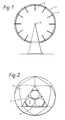
- a thermally driven gas resonance device comprises a generally spherical chamber 1 and a pulsed combustor 2 positioned centrally within the chamber.
- the combustor 2 includes a tuned non-return valve such as that described in our earlier application EP-A-0267727.
- a combustion mixture of air and an appropriate fuel gas is admitted to the chamber 1 via the tuned non-return valve.
- the combustion mixture is periodically ignited at a frequency matched to the resonant frequency of the spherical chamber 1.
- a sparking plug is provided in the combustor to cause the initial ignition but subsequently the pulsed combustion is self-sustaining.
- the combustion mixture may be supplied to the chamber 1 via a resonant gas-supply tube which extends into the chamber 1 and is tuned to supply the combustion mixture in pulses at the required pulse repetition frequency.
- the operation of the combustor in the manner described above provides a pulsed heat source at the centre of the chamber 1 which produces a substantially spherical expanding wave front. Since the frequency of the combustor is matched to the resonant frequency of the chamber the combustor drives resonant modes of the chamber, maximising the efficiency with which the heat energy of combustion is converted into the mechanical energy associated with the pressure swings in the gas within the chamber 1. In the first example described this mechanical energy is used to drive a gas separator used for oxygen enrichment.
- the generally spherical chamber 1 is defined by a hollow icosohedral shell 3 formed of generally triangular elements 4.
- Open-ended exhaust tubes 5 extend into the chamber 1 from the outer surface of the shell 3.
- the radially innermost ends of the tubes 5 lie at points spaced from the centre of the spherical chamber 1 by about three-quarters of the sphere radius.
- Pipes connected to an external water supply are positioned concentrically within the exhaust tubes 5. These pipes provide inwardly directed water sprays. A small proportion of the water is converted to steam by the heat source during thermal pulses and so supplements the production of mechanical power. The remaining mist of water droplets cools the gases in the chamber during the subsequent expansion cycle, prior to recompression, so removing excess heat energy and further increasing the efficiency of the device. Heated water aggregated from water droplets returned to the internal spherical surface of the chamber 1 is drained away at the base and may be cooled and recirculated.
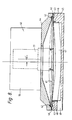
- the modules in the chamber 1 are formed as gas-separator modules such as that shown with its outer surface cut-away in the element 4′ of Figure 2.
- Each gas-separator module comprises a number of circular elements 7, each element 7 comprising a dished zeolite bed 8 and a diaphragm 9 covering the bed 8 on its inwardly facing surface.
- Each element 7 is 0.8 metres in diameter and up to 72 such elements may be provided across the inner surface of a chamber 1 or 2 metres radius.
- the pressure-swings at the periphery of the chamber 1 drive the diaphragm 8 back and forth in the radial direction, that is the direction transverse to the surface of the bed 8.
- Air is drawn in through an annular inlet 10 surrounding the periphery of the bed 8 and driven through the bed 8 in the manner described in further detail below.
- Oxygen-enriched gas leaving the bed 8 at its lower surface is collected under a skirt 11 and transferred via ducts 12 to the tubular framework 13 of the icosohedral shell 3.
- the tubular framework 13 is connected in common to all the gas separator modules 6 and provides a path from the modules 6 to an outlet (not shown) from which the the oxygen-enriched gas is piped away.
- the diaphragm 9 also serves to provide a valving arrangement which ensures that air is admitted and depleted air exhausted at appropriate points in the oscillatory cycle.
- the diaphragm 9 is dimensioned to have the same resonant frequency as the chamber 1.
- the diaphragm 9 is formed of steel with a diameter of 0.8 metres and a thickness of 6 mm.
- the diaphragm 9 is suspended at its edges outside the bed 8 so that in its equilibrium position it clears the periphery of the bed 8 but touches the bed 8 at a valve seat 14 formed some 10 cm in from the outer edge of the bed 8.
- the part of the bed 8 extending radially outwards from this valve seat 14 is sealed so as to be impervious to air and the region of contact between the diaphragm 9 and the bed 8 serves to provide a valve which controls the intake of air from the port 10 to the main part of the bed 8.
- a cylindrical exhaust outlet 15 which, when the diaphragm is in its equilibrium position, is sealed by a conical valve member 16.
- the valve member 16 rides on a spindle 17 fixed to the centre of the diaphragm 9.
- the diaphragm 9 then moves downwards towards the bed 8 again.
- the diaphragm 9 again reaches its equilibrium position and closes the inlet and exhaust valves. It should be noted that although there is a delay between the opening of the inlet and outlet valve resulting from the play on the spindle 17 when they close at time t2 they do so simultaneously.
- the pressure under the diaphragm 9 increases driving the fresh air drawn through the annular inlet 10 into the zeolite bed 8.
- the zeolite acts as a molecular sieve, preferentially adsorbing the nitrogen from the air so that the gas passing out through the bottom of the bed 8 is oxygen enriched/nitrogen depleted.
- time t3 which is point of maximum displacement in the opposite direction, towards the bed 8, the diaphragm 9 moves back towards its equilibrium position reducing the pressure above the bed 8. Under this reduced pressure nitrogen is desorbed from the bed 8 and drawn back towards the surface.
- the cycle is repeated with the next intake of air driving the oxygen depleted, nitrogen-rich gas from the surface of the bed 8 to the exhaust outlet 15.
- the cycle accelerates the gas throughout its passage across the face of the bed so that when it reaches the outlet 15 its momentum carries it away from the chamber 1 as a puff of gas which does not mix with the intake to the bed.
- the oxygen is driven down through the bed to its outer surface where it is conducted away in the manner already described.
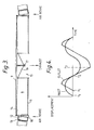
- FIG. 5 A modification of the gas separator module is shown in Figures 5, 6 and 7.
- an annular valve seat 31 surrounds a dished bed of adsorbent material 32.
- a thick tuned diaphragm 33 resonates at the resonance frequency of the substantially spherical chamber 1 (not shown in Figure 5).
- the bed 32 and annular valve seat 31 are generally similar to the bed 8 and seat 14 of the first example.
- the diaphragm 33 is unbalanced and includes an added mass 34 on one side and a cut-away portion 35, shown in Figure 6, on its other side.
- This assymetry in the diaphragm 33 leads to a harmonic oscillation being generated in the diaphragm 33 as it is oscillated backwards and forwards in the radial direction at the fundamental frequency by the spherical wavefronts propagating in the chamber 1.
- This harmonic oscillation has the form of a transverse wave moving from left to right as shown in Figure 5.
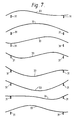
- Figure 7 illustrates this effect diagrammatically.
- the diaphragm is represented by a line with the amplitude of the transverse oscillation greatly exaggerated to illustrate how, as the diaphragm 33 is moving away from the bed 32, first the left hand side, as shown in Figures 5, 6 and 7 lifts away from the annular seat 31 so allowing fresh air to be drawn in to the gap formed between the diaphragm 33 and the valve seat 31 at the left hand side of the gas separator module. Further movement of the diaphragm 33 away from the adsorbent bed 32 further reduces the pressure above the adsorbent bed 32, draws in more fresh air from the left hand side of the bed 32 and draws out more of the depleted nitrogen rich gas from the bed 32.
- the transverse movement of air across the face of the dished bed 32 leads to an effective scavenge of the depleted, nitrogen rich air from the surface of the bed 32 and out of the right hand side of the gas separator module between the right hand side of the annular seat 31 and the diaphragm 33.
- the diaphragm 33 continues to move towards the adsorbent bed it eventually seats against the entire circumference of the annular seal 31 so closing the valve and pressurising the fresh air introduced into the module and forcing it into the adsorbent bed 32. After reaching a point of maximum deflection towards the bed 32 the diaphragm again starts to return and move away from the bed 32.
- the left hand side of the diaphragm which first lifts from its annular seat 31 to allow fresh air to enter the module from the left hand side and the process is repeated.
- the transverse wave action that is induced in the diaphragm 33 also encourages the movement of air in the transverse direction from the left hand side to the right hand side of the gas separator module.
- a pressure-swing gas separator such as that described above offers both greater efficiency and lower capital costs by comparison with a conventional oxygen production plant such as a cryogenic oxygen recovery unit.
- a 2 metre radius sphere having its surface entirely covered by gas-separation modules is capable of producing luo tonnes per day of 98% oxygen with an oxygen recovery ratio, that is the ratio by volume of oxygen input to oxygen output, of 100:15 and a specific energy consumption, that is the mechanical energy input required to produce 1 kilogram of oxygen, of 0.125 kW hr/kg.
- the 98% oxygen mixture produced is suitable for use in industrial processes such as iron and steel-making but may also be used for other purposes such as sewage-treatment or the generation of oxgyen for medical use.
- the scale of the device and the concentration of the oxygen produced may be varied to suit the needs of the particular application.
- a gas-separator unit formed by a single circular bed and diaphragm such as that described above may be used in an ogival gas resonance device such as that described in the European application cited above.
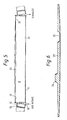
- the second example of pressure swing gas separator uses a bed and diaphragm arrangement similar to that described in the modification of the first example but the diaphragm is driven by an electrical actuator 40.
- the gas separator comprises a diaphragm 41 having its periphery clamped between an O-ring 42 and a number of equiangularly spaced balls 43.
- the O-ring 42 is received in an annular groove in the top part of a housing 44 whilst the balls 43 are received in the bottom part 45 of the housing.
- the two halves of the housing are clamped together by bolts 46 to clamping the diaphragm 41 between the O-ring 42 and balls 43.
- a dished bed 47 filled with adsorbent material is located in the bottom half 45 of the housing and surrounded by an annular seal 48 which extends close to the periphery of the diaphragm 41.
- a gas outlet 49 in communication with the rear face of the bed 47 leads away from the lower half 45 of the housing.
- the upper part 44 of the housing supports the electrical actuator 40 which consists of a stator 50 which may be a permanent magnet or preferably, is an electro-magnetic energised by a DC field coil.
- An armature, 51 formed by a moving coil is connected to the diaphragm 41 eccentrically.
- Figure 8 illustrates the offset OFF between the centre of the diaphragm and the centre of the armature.
- the arrangement of the electrical actuator 40 is generally similar to that used for driving loudspeakers.
- a single phase mains AC current is connected to the moving coil armature and, in response to the alternating current the armature moves up and down, as shown in Figure 8 to cause the diaphragm to oscillate.
- the diaphragm is arranged to oscillate at the mains frequency. Because of the lateral offset between the axes of the diaphragm and that of the armature the diaphragm oscillates as described above with reference to Figure 7.
- Adsorption/desorbtion with rising and falling fluid pressure is capable of separation of species, such as nitrogen and oxygen from air using a zeolite molecular sieve in the form of a porous bed of graded or uniformly sized particles.
- species such as nitrogen and oxygen from air
- a zeolite molecular sieve in the form of a porous bed of graded or uniformly sized particles.
- mixed gases are introduced at the top of the bed, and one component is withdrawn at a lower flow rate at the base of the bed.
- Throughputs are determined by the required purity of the separated fraction.
- the energy efficiency of separation is potentially high for provision of separated gas delivered at atmospheric pressure, and is already higher in practical applications than with any of the cryogenic separation routes.
- Molecular selectivity is the basis for separations conducted by adsorption and it is known, for instance, that nitrogen is preferentially adsorbed at a zeolite surface because of its different molecular configuration from that of oxygen.
- the adsorption process is also completely reversible with change of pressure.
- the molecular selectivity of zeolite for nitrogen from N2/O2 mixtures is held to be 2.8 over a wide range of pressures at ambient temperatures. Since molecular processes are intrinsically fast, it is evident that rates of adsorption are limited by diffusion rather than molecular adsorption, since inert components such as argon in air are invariably present and effectively form a barrier between the nitrogen and the adsorbent bed.
- the adsorption of two species B and C of similar densities at a clean surface is considered to be governed by the product of the molecular selectivity s and the relative rates of arrival of the species at the surface, in terms of an inert boundary layer of species A and thickness ⁇ impeding the flow to the surface, and the mutual diffusivity D of the other two species through this boundary layer.
- Stefan's law indicates that the overall mass diffusion rate q per unit area of adsorbed species at the interface is, where ⁇ o is the overall density and c A is the small fractional concentration of the inert species A. (The negative sign accounts for the negative logarithm).
- a qualitative evaluation of equation [1] shows that comparatively high rates of adsorption can be foreseen in an adsorption bed of small particles.
- Equation [2] demonstrates that the instantaneous effective selectivity ⁇ in the presence of the boundary layer is simply, which exceeds s at the start of the process and is progressively reduced.
- Equation [7] may be written as Then, for successive pressure swings relating to the non-adsorbed delivery fraction, corresponding with concentration terms k0, k1, k2,....k n , the cumulative value 1 - x is given by, so that the incremental result is the same as for one pressure swing.
- average work rate per unit bed area during cyclic operations is and that the component of specific energy of separation attributed to bed friction (kWhr/m3 of component) is where 1 - x is the recovery ratio related to a particular concentration, derived from equation [7].
- These expressions continue to be independent of operating frequency, and the specific energy is also independent of v.
- the relevant expression may be applied similarly to characterise non-resonant separation beds, and is well correlated with results obtained from them. The enhanced economy of resonant operation with much lower pressure amplitudes in accordance with this invention is thereby emphasized.
- Bead volume Number of beads per unit volume.
- RPSA rapid pressure swing adsorption system
- RPSA rapid pressure swing adsorption system
- the acoustic system uses resonant oscillations in order to conserve the pressure energy contained in the gas component rejected after separation of another component.
- usable frequency bands of the two systems are likely to be contiguous, and without overlap.
- a sufficient degree of adsorption is obtainable at enhanced frequency to obviate the need to make use of saturation, and this is why the acoustic bed can achieve the same volumetric loadings at lower entry pressures and velocities and higher energy efficiencies.
- Both variants use a superimposed steady gas flow through the bed to extract the separated component, and the proportion extracted in this way determines its purity. Of necessity therefore, both variants make use of saturation at the low, constant pressure at the base of the bed, since adsorption eventually ceases when pressure is constant at any value.
- the bed loading criterion for acoustic pressure swing separation is entry velocity and not frequency. At high frequencies bed diameters are preferably small in order to limit energy losses from high scavenge velocities.
Applications Claiming Priority (2)
| Application Number | Priority Date | Filing Date | Title |
|---|---|---|---|
| GB888826378A GB8826378D0 (en) | 1988-11-10 | 1988-11-10 | Pressure swing gas separation |
| GB8826378 | 1988-11-10 |
Publications (1)
| Publication Number | Publication Date |
|---|---|
| EP0368649A1 true EP0368649A1 (de) | 1990-05-16 |
Family
ID=10646678
Family Applications (1)
| Application Number | Title | Priority Date | Filing Date |
|---|---|---|---|
| EP89311584A Withdrawn EP0368649A1 (de) | 1988-11-10 | 1989-11-09 | Druckwechsel-Gastrennung |
Country Status (14)
| Country | Link |
|---|---|
| EP (1) | EP0368649A1 (de) |
| JP (1) | JPH02237611A (de) |
| CN (1) | CN1046856A (de) |
| AU (1) | AU619920B2 (de) |
| CA (1) | CA2002668A1 (de) |
| DK (1) | DK560589A (de) |
| FI (1) | FI89771C (de) |
| GB (1) | GB8826378D0 (de) |
| IN (1) | IN174881B (de) |
| MY (1) | MY104262A (de) |
| NO (1) | NO176869C (de) |
| NZ (1) | NZ231299A (de) |
| PT (1) | PT92287B (de) |
| ZA (1) | ZA898507B (de) |
Cited By (5)
| Publication number | Priority date | Publication date | Assignee | Title |
|---|---|---|---|---|
| EP0879630A2 (de) * | 1997-05-23 | 1998-11-25 | The BOC Group plc | Verfahren und Vorrichtung zur Gastrennung |
| US6511526B2 (en) | 2001-01-12 | 2003-01-28 | Vbox, Incorporated | Pressure swing adsorption gas separation method and apparatus |
| US8394178B2 (en) | 2009-07-22 | 2013-03-12 | Vbox, Incorporated | Apparatus for separating oxygen from ambient air |
| US9943678B2 (en) | 2005-12-02 | 2018-04-17 | C. R. Bard, Inc. | Pressure activated proximal valves |
| US10357628B2 (en) | 2005-02-09 | 2019-07-23 | 3B Medical Manufacturing Llc | Removable cartridge for oxygen concentrator |
Citations (6)
| Publication number | Priority date | Publication date | Assignee | Title |
|---|---|---|---|---|
| FR1382688A (fr) * | 1963-02-15 | 1964-12-18 | Lindes Eismachinen Ag Ges | Procédé et installation pour l'enrichissement d'un élément constituant dans un mélange gazeux |
| EP0008619A1 (de) * | 1978-06-26 | 1980-03-19 | Union Carbide Corporation | Verfahren zur schnellen adiabatischen Druckwechseladsorption |
| EP0013680A1 (de) * | 1978-12-27 | 1980-08-06 | Union Carbide Corporation | Adiabatisches Schnell-Druckwechsel-Adsorptionsverfahren und Apparat zur Sauerstofferzeugung mit mehreren Zeolith-Molekularsiebbetten |
| US4732580A (en) * | 1986-10-01 | 1988-03-22 | The Boc Group, Inc. | Argon and nitrogen coproduction process |
| EP0267727A2 (de) * | 1986-11-06 | 1988-05-18 | The Haser Company Limited | Gasresonanzvorrichtung |
| US4767314A (en) * | 1987-06-08 | 1988-08-30 | Engineered Air Systems, Inc. | Pulse jet engine assembly |
-
1988
- 1988-11-10 GB GB888826378A patent/GB8826378D0/en active Pending
-
1989
- 1989-11-07 NZ NZ231299A patent/NZ231299A/xx unknown
- 1989-11-07 IN IN826MA1989 patent/IN174881B/en unknown
- 1989-11-08 NO NO894454A patent/NO176869C/no unknown
- 1989-11-08 ZA ZA898507A patent/ZA898507B/xx unknown
- 1989-11-09 EP EP89311584A patent/EP0368649A1/de not_active Withdrawn
- 1989-11-09 FI FI895338A patent/FI89771C/fi not_active IP Right Cessation
- 1989-11-09 DK DK560589A patent/DK560589A/da not_active Application Discontinuation
- 1989-11-09 CA CA002002668A patent/CA2002668A1/en not_active Abandoned
- 1989-11-09 JP JP1290131A patent/JPH02237611A/ja active Pending
- 1989-11-09 AU AU44533/89A patent/AU619920B2/en not_active Ceased
- 1989-11-10 PT PT92287A patent/PT92287B/pt not_active IP Right Cessation
- 1989-11-10 MY MYPI89001545A patent/MY104262A/en unknown
- 1989-11-10 CN CN89109181A patent/CN1046856A/zh active Pending
Patent Citations (6)
| Publication number | Priority date | Publication date | Assignee | Title |
|---|---|---|---|---|
| FR1382688A (fr) * | 1963-02-15 | 1964-12-18 | Lindes Eismachinen Ag Ges | Procédé et installation pour l'enrichissement d'un élément constituant dans un mélange gazeux |
| EP0008619A1 (de) * | 1978-06-26 | 1980-03-19 | Union Carbide Corporation | Verfahren zur schnellen adiabatischen Druckwechseladsorption |
| EP0013680A1 (de) * | 1978-12-27 | 1980-08-06 | Union Carbide Corporation | Adiabatisches Schnell-Druckwechsel-Adsorptionsverfahren und Apparat zur Sauerstofferzeugung mit mehreren Zeolith-Molekularsiebbetten |
| US4732580A (en) * | 1986-10-01 | 1988-03-22 | The Boc Group, Inc. | Argon and nitrogen coproduction process |
| EP0267727A2 (de) * | 1986-11-06 | 1988-05-18 | The Haser Company Limited | Gasresonanzvorrichtung |
| US4767314A (en) * | 1987-06-08 | 1988-08-30 | Engineered Air Systems, Inc. | Pulse jet engine assembly |
Cited By (13)
| Publication number | Priority date | Publication date | Assignee | Title |
|---|---|---|---|---|
| EP0879630A2 (de) * | 1997-05-23 | 1998-11-25 | The BOC Group plc | Verfahren und Vorrichtung zur Gastrennung |
| EP0879630A3 (de) * | 1997-05-23 | 1999-04-07 | The BOC Group plc | Verfahren und Vorrichtung zur Gastrennung |
| US6511526B2 (en) | 2001-01-12 | 2003-01-28 | Vbox, Incorporated | Pressure swing adsorption gas separation method and apparatus |
| US6641644B2 (en) | 2001-01-12 | 2003-11-04 | Vbox, Incorporated | Pressure swing adsorption gas separation method and apparatus |
| US10357628B2 (en) | 2005-02-09 | 2019-07-23 | 3B Medical Manufacturing Llc | Removable cartridge for oxygen concentrator |
| US10702669B2 (en) | 2005-02-09 | 2020-07-07 | Vbox, Incorporated | Removable cartridge for oxygen concentrator |
| US11389614B2 (en) | 2005-02-09 | 2022-07-19 | Vbox, Incorporated | Removable cartridge for oxygen concentrator |
| US9943678B2 (en) | 2005-12-02 | 2018-04-17 | C. R. Bard, Inc. | Pressure activated proximal valves |
| US11305102B2 (en) | 2005-12-02 | 2022-04-19 | C. R. Bard, Inc. | Pressure activated proximal valves |
| US8597408B2 (en) | 2009-07-22 | 2013-12-03 | Vbox, Incorporated | Apparatus for separating oxygen from ambient air |
| US8695600B2 (en) | 2009-07-22 | 2014-04-15 | Vbox, Incorporated | Method of separating and distributing oxygen |
| US10335570B2 (en) | 2009-07-22 | 2019-07-02 | 3B Medical Inc. | Method of separating and distributing oxygen |
| US8394178B2 (en) | 2009-07-22 | 2013-03-12 | Vbox, Incorporated | Apparatus for separating oxygen from ambient air |
Also Published As
| Publication number | Publication date |
|---|---|
| JPH02237611A (ja) | 1990-09-20 |
| AU4453389A (en) | 1990-05-17 |
| GB8826378D0 (en) | 1988-12-14 |
| AU619920B2 (en) | 1992-02-06 |
| PT92287B (pt) | 1995-08-09 |
| CN1046856A (zh) | 1990-11-14 |
| MY104262A (en) | 1994-02-28 |
| NO176869C (no) | 1995-06-14 |
| CA2002668A1 (en) | 1990-05-10 |
| IN174881B (de) | 1995-03-25 |
| NO894454L (no) | 1990-05-11 |
| NO894454D0 (no) | 1989-11-08 |
| FI89771C (fi) | 1993-11-25 |
| NZ231299A (en) | 1991-10-25 |
| DK560589D0 (da) | 1989-11-09 |
| PT92287A (pt) | 1990-05-31 |
| NO176869B (no) | 1995-03-06 |
| ZA898507B (en) | 1991-07-31 |
| FI89771B (fi) | 1993-08-13 |
| FI895338A0 (fi) | 1989-11-09 |
| DK560589A (da) | 1990-05-14 |
Similar Documents
| Publication | Publication Date | Title |
|---|---|---|
| US5069688A (en) | Pressure swing gas separation | |
| US5120332A (en) | Gas resonance device | |
| US4552571A (en) | Oxygen generator with two compressor stages | |
| WO1992001503A1 (en) | Adsorptive gas separator with inertial energy exchange | |
| US6722352B2 (en) | Pressure-swing adsorption system for internal combustion engines | |
| EP0368649A1 (de) | Druckwechsel-Gastrennung | |
| CA1084421A (en) | Recovery of gases from gaseous mixtures | |
| GB1529779A (en) | Gas-mixture fractionating apparatus | |
| EP0368650A1 (de) | Gasresonanzvorrichtung | |
| KR102524769B1 (ko) | Co₂흡착 및 포획을 위한 유형 v 흡착제 및 기체 농축의 용도 | |
| JPH10328520A (ja) | ガスの分離 | |
| Suzuki et al. | Piston-driven ultra rapid pressure swing adsorption | |
| US4141699A (en) | Process for separating gas mixtures, especially isotopes | |
| JPH0347512A (ja) | 往復動式揺動圧力型ガス分離装置 | |
| JP2755773B2 (ja) | 圧力スイング式ガス分離装置 | |
| WO2023217740A1 (en) | A process for capture of carbon dioxide | |
| SU1105738A1 (ru) | Установка дл производства тепла и твердой углекислоты | |
| SU1678759A1 (ru) | Способ извлечени брома | |
| JPH0295409A (ja) | 窒素ガス分離方法 | |
| JPH06210119A (ja) | 酸素濃縮化装置 | |
| JPH06218216A (ja) | 酸素富化空気生成装置 | |
| JPS57119890A (en) | Ozone injecting device | |
| JPS6268117A (ja) | 車両室内用酸素供給装置 | |
| RU93010331A (ru) | Способ обеспечения массообмена (тепломассообмена) между жидкостью и газом и аппарат для осуществления этого способа "тепломассообменник" | |
| RU94007846A (ru) | Способ смешения аэрозольных мазутных и газомазутных смесей в смесительных камерах |
Legal Events
| Date | Code | Title | Description |
|---|---|---|---|
| PUAI | Public reference made under article 153(3) epc to a published international application that has entered the european phase |
Free format text: ORIGINAL CODE: 0009012 |
|
| AK | Designated contracting states |
Kind code of ref document: A1 Designated state(s): AT BE CH DE ES FR GB GR IT LI LU NL SE |
|
| 17P | Request for examination filed |
Effective date: 19901102 |
|
| 17Q | First examination report despatched |
Effective date: 19920803 |
|
| STAA | Information on the status of an ep patent application or granted ep patent |
Free format text: STATUS: THE APPLICATION IS DEEMED TO BE WITHDRAWN |
|
| 18D | Application deemed to be withdrawn |
Effective date: 19950503 |