EP0367906B1 - Nach rechts und links drehbares Ofendach - Google Patents
Nach rechts und links drehbares Ofendach Download PDFInfo
- Publication number
- EP0367906B1 EP0367906B1 EP89113025A EP89113025A EP0367906B1 EP 0367906 B1 EP0367906 B1 EP 0367906B1 EP 89113025 A EP89113025 A EP 89113025A EP 89113025 A EP89113025 A EP 89113025A EP 0367906 B1 EP0367906 B1 EP 0367906B1
- Authority
- EP
- European Patent Office
- Prior art keywords
- coolant
- roof
- drain
- furnace
- outlets
- Prior art date
- Legal status (The legal status is an assumption and is not a legal conclusion. Google has not performed a legal analysis and makes no representation as to the accuracy of the status listed.)
- Expired - Lifetime
Links
- 239000002826 coolant Substances 0.000 claims description 188
- 238000010891 electric arc Methods 0.000 claims description 12
- 238000004891 communication Methods 0.000 claims description 10
- 239000007921 spray Substances 0.000 claims description 9
- 238000005192 partition Methods 0.000 claims description 8
- 238000009434 installation Methods 0.000 description 32
- 239000002516 radical scavenger Substances 0.000 description 10
- XLYOFNOQVPJJNP-UHFFFAOYSA-N water Substances O XLYOFNOQVPJJNP-UHFFFAOYSA-N 0.000 description 6
- 229910000831 Steel Inorganic materials 0.000 description 5
- 239000010959 steel Substances 0.000 description 5
- 238000001816 cooling Methods 0.000 description 4
- 238000009628 steelmaking Methods 0.000 description 4
- 230000000694 effects Effects 0.000 description 3
- 239000012768 molten material Substances 0.000 description 3
- 239000002893 slag Substances 0.000 description 3
- 230000008878 coupling Effects 0.000 description 2
- 238000010168 coupling process Methods 0.000 description 2
- 238000005859 coupling reaction Methods 0.000 description 2
- 238000009835 boiling Methods 0.000 description 1
- 239000012530 fluid Substances 0.000 description 1
- 239000003517 fume Substances 0.000 description 1
- 230000005484 gravity Effects 0.000 description 1
- 239000007788 liquid Substances 0.000 description 1
- 238000012423 maintenance Methods 0.000 description 1
- 239000008400 supply water Substances 0.000 description 1
Images


Classifications
-
- F—MECHANICAL ENGINEERING; LIGHTING; HEATING; WEAPONS; BLASTING
- F27—FURNACES; KILNS; OVENS; RETORTS
- F27D—DETAILS OR ACCESSORIES OF FURNACES, KILNS, OVENS OR RETORTS, IN SO FAR AS THEY ARE OF KINDS OCCURRING IN MORE THAN ONE KIND OF FURNACE
- F27D1/00—Casings; Linings; Walls; Roofs
- F27D1/12—Casings; Linings; Walls; Roofs incorporating cooling arrangements
-
- F—MECHANICAL ENGINEERING; LIGHTING; HEATING; WEAPONS; BLASTING
- F27—FURNACES; KILNS; OVENS; RETORTS
- F27D—DETAILS OR ACCESSORIES OF FURNACES, KILNS, OVENS OR RETORTS, IN SO FAR AS THEY ARE OF KINDS OCCURRING IN MORE THAN ONE KIND OF FURNACE
- F27D1/00—Casings; Linings; Walls; Roofs
- F27D1/18—Door frames; Doors, lids or removable covers
- F27D1/1808—Removable covers
- F27D1/1816—Removable covers specially adapted for arc furnaces
Definitions
- This invention relates to an improved furnace roof and, in particular, an improved roof for large scale molten material processing furnaces such as electric arc steel making furnaces and the like.
- the roof mast structure in electric arc furnaces operates to reposition the roof relative to the underlying furnace and open the furnace top, for example, during initial loading or charging of scrap into the furnace, and at other times during or following furnace operation.
- the mast structure generally includes a post located adjacent to the furnace vessel upon which pivots a roof supporting structure.
- This supporting structure usually comprises arms extending out over the top of the furnace and downwardly extending chains or bars to which the roof itself is attached.
- the supporting structure is able to lift up the roof and swing it to the side or some other position to allow access to the open top of the furnace.
- These pivoting mast and roof structures are generally made to swing the roof away from the furnace in only one direction, that is, as seen in a downward plan view, either clockwise or counterclockwise around the mast post.
- These clockwise and counterclockwise-opening furnace roofs are respectively known as “right-handed” and “left handed” furnace roofs because of the direction of swings opening the furnace relative to the mast post. Because the furnace roof may be opened during furnace operation or immediately afterwards, it is important that heat sensitive portions of the mast and roof structure exposed to the heat be adequately shielded, including the roof coolant connections.
- the coolant inlet and outlet on the furnace roof and the associated connecting hoses are positioned so that they are opposite the side of the roof which swings over the open furnace.
- the hose connections are generally as close to the mast post as possible to minimize the length of hose and the possibility for interference.
- the left-handed roof configuration will have the coolant inlet and outlet connectors at approximately a 7 to 8 o'clock position, whereas the right-handed roof configuration will have the coolant inlet and outlets in approximately a 4 to 5 o'clock position.
- Electric arc steel making installations will generally keep a backup or spare roof on hand for changeover during maintenance or emergencies. If a steel making installation has arc furnaces with both left- and right-handed roofs, there will have to be kept on hand both a left-handed and right-handed roof spare, even though the furnaces may be identical in other respects. Except for the location of coolant inlet and outlets on the furnace roof, only one spare might otherwise be required for backup purposes, at a considerable cost savings in direct expenditure and inventory costs.
- the invention provides a furnace roof comprising the furnace installation having at least a portion thereof cooled by a coolant, and means on the roof to secure the roof to a mast structure or other means to remove the roof from the furnace in either a first or second predetermined direction.
- a coolant drain system divided into at least two segments, is provided for receiving spent coolant from the spray cooled portion of the roof.
- a first set of coolant outlets is provided on the roof drain system for connection with a coolant collection system to permit removal of coolant when the roof is secured for removal in the first direction.
- Each of the outlets in the first set is connected to a different drain system segment.
- a second set of coolant outlets, spaced from the first set of coolant outlets, is additionally provided on the roof drain system for connection with a coolant collection system to permit removal of coolant when the roof is secured for removal in the second direction.
- Each of the outlets in the second set is connected to a different drain system segment.
- each set of coolant outlets comprises an adjacent pair of outlet pipes.
- Removable connection means such as a U-shaped conduit, may be secured between the outlets disconnected from the coolant collection system to provide unobstructed communication between the coolant outlets and permit flow of spent coolant between the drain system segments.
- the invention is especially adapted for use with spray-cooled furnace roofs in tilting electric arc furnaces and the like.
- Such roofs have upper and lower panels which define a space therebetween and means for direction a spray of coolant, preferably water, against the lower panels to maintain the lower panels at a desired temperature range.
- the coolant collection system utilizes jet pump or other means for maintaining a pressure differential between the roof interior and the coolant outlets to remove spent coolant from the roof.
- the coolant drain system preferably includes drain inlets on opposing sides of the roof and aligned perpendicular to a tilting axis of the furnace.
- One of the drain inlets is in direct communication, via one of the drain system segments, with one of the drain outlets connected to the coolant collection system, while the opposite drain inlet is in communication, via the connection means and another drain system segment, with another of the drain outlets.
- Separate pump means may be utilized for each of the connected drain outlets for independently removing spent coolant from each of the drain outlets and associated drain inlets.
- Fig. 1 is a side elevational view of a typical electric furnace installation showing a furnace vessel, a furnace roof in a raised position over the furnace vessel and a mast supporting structure for the roof.
- Fig. 2 is a top plan view, partially cut away and partially in section, of a first embodiment of the furnace roof and supporting mast structure of Fig. 1.
- Fig. 2a is a side cross sectional view along the line 2a-2a of Fig. 2.
- Fig. 3 illustrates a top plan view of an electric arc furnace installation showing the furnace roof system of the present invention being utilized in a left-handed configuration as it is swung away in a counterclockwise direction from an arc furnace vessel.
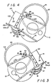
- Fig. 4 is a top plan view of an electric arc furnace installation showing the roof system of the present invention being utilized as a right-handed furnace roof as it is swung away in a clockwise direction from an arc furnace vessel.
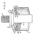
- Fig. 5 is an end elevational view of the electric furnace installation of Fig. 1.
- Fig. 6 is a top plan view, partially cut away and partially in section, of a second embodiment of the furnace roof and supporting mast structure of Fig. 1.
- Fig. 6a is a side cross sectional view along the line 6a-6a of Fig. 6.
- FIG. 1-6a Preferred embodiments of the present invention are illustrated in Figs. 1-6a in which like numerals refer to like features of the invention.
- the figures illustrate a typical electric arc furnace installation as used for steel-making, although the furnace roof system of the present invention can be utilized in any type of molten material processing vessel in which the roof may be removed in different directions.
- Figs. 1, 2 and 5 illustrate a first embodiment of the electric arc furnace installation in side, top and end views, respectively.
- the circular water-cooled furnace roof 10 is shown being supported by a furnace mast structure 14 in a slightly raised position directly over the rim 13 of electric arc furnace vessel 12.
- the roof 10 is attached by chains, cables or other roof lift members 53 to mast arms 18 and 20 which extend horizontally and spread outward from mast support 22.
- Mast support 22 is able to pivot around point 24 on the upper portion of vertical mast post 16 to swing roof 10 horizontally to the side to expose the open top of furnace vessel 12 during charging or loading of the furnace, and at other appropriate times during or after furnace operation.
- Electrodes 15 are shown extending into opening 32 from a position above roof 10. During operation of the furnace, electrodes 15 are lowered through electrode ports of a delta in the central roof opening 32 into the furnace interior to provide the electric arc-generated heat to melt the charge. Exhaust port 19 permits removal of fumes generated from the furnace interior during operation.
- the furnace system is mounted on trunnions or other means (not shown) to permit the vessel 12 to be tilted in either direction to pour off slag and molten steel. As shown in end elevational view in Fig. 5, the entire furnace may tilt to either the right or the left to pour off slag or steel from openings below furnace rim 13 (not shown) on the extreme right and left of vessel 12. The furnace will tilt about 15° from horizontal to pour off slag in one direction and will tilt about 45° from horizontal to pour steel in the opposite direction.
- the furnace roof system shown in Figs. 1, 2, 3 and 5 is set up to be used as a left-handed system whereby the mast 14 may pick up roof 10 and swing it horizontally in a counterclockwise manner (as seen from above) clear of the furnace rim 13 to expose the furnace interior.
- a roof cooling system is incorporated therein.
- the cooling system utilizes a fluid coolant such as water or some other suitable liquid to maintain the furnace roof at a predetermined temperature. Any suitable cooling system may be utilized, although the systems described in the aforementioned U.S. Patent No. 4,715,042 and U.S. Patent 4 815 096.
- Coolant inlet pipe 26 and outlet pipes 28a and 28b comprise the coolant connection means for this left-hand configured furnace roof
- An external circulation system (not shown) utilizes coolant supply pipe 30 and coolant drain pipes 36a and 36b, respectively, to supply coolant to and drain coolant from the coolant connection means of roof 10.
- the coolant circulation system normally comprises a coolant supply system and a coolant collection system, and may also include coolant recirculation means.
- coolant supply pipe 30 Attached to coolant supply pipe 30 is flexible coolant supply hose 31 which is attached by quick release coupling or other means to coolant inlet pipe 26 on the periphery of furnace roof 10.
- inlet 26 leads to an inlet manifold 29 which extends around central delta opening 32 in the unpressurized interior of roof 10.
- branching radially outward from manifold 29 in a spoke-like pattern is a plurality of spray header pipes 33 to deliver the coolant to the various sections of the roof interior 23.
- each header 33 Protruding downward from various points on each header 33 is a plurality of spray nozzles 34 which direct coolant in a spray or fine droplet pattern to the upper side of roof lower panels 38, which slope gradually downwardly from center portion of the roof to the periphery.
- the cooling effect of the spray coolant on the lower panels 38 enables the temperature thereon to be maintained at a predetermined temperature range, which is generally desired to be less than the boiling point of the coolant (100°C in the case of water).
- the drain system shown is a manifold which is made of rectanqular cross section tubing or the like divided into segments 47a and 47b. As seen in Fig. 2, drain openings 51a and 51b are on opposite sides of the roof and aligned perpendicular to the tilting axis of the furnace.
- the drain manifold takes the form of a closed channel extending around the interior of the roof periphery at or below the level of roof lower panels 38 and is separated by partitions or walls 48 and 50 into separate draining segments 47a and 47b.
- Drain manifold segment 47a connects drain openingss 51a, 51b and 51c with coolant outlet pipe 28a. Drain manifold segment 47b is in full communication with segment 47a via connection means 44 (in a manner which will be explained in more detail later) and connects drain openings 51a, 51b and 51c with coolant outlet pipe 28b.
- Flexible coolant drain hose 37 connects outlet 28a to coolant drain pipe 36a while flexible coolant drain hose 35 connects outlet 28b and coolant drain pipe 36b.
- Quick release or other coupling means may be used to connect the hoses and pipes.
- the coolant collection means to which coolant drain pipes 36a and 36b are connected will preferably utilize jet or other pump means to quickly and efficiently drain the coolant from the roof 10. Any suitable other means to assist draining of the coolant may also be utilized.
- the present invention also provides for a second coolant connection means which may be used in a right-handed installation of roof 10.
- This second or right-handed coolant connection means comprises coolant inlet 40 and coolant outlet 42.
- the left- and right-handed coolant connection means are on opposite sides of roof 10 relative to a line passing through mast pivot point 24 and the center of the roof, and lie in adjacent quadrants of the roof.
- right-handed coolant inlet pipe 40 is connected to inlet manifold 29.
- right-handed coolant outlet 42 includes separate outlet pipes 42a and 42b which communicate with the separate segments 47a and 47b of the coolant drain manifold which are split by partition 50.
- the present invention also provides for capping means to seal the individual roof coolant inlets and outlets.
- a cap 46 may be secured over the opening to coolant inlet 40.
- a removable U-shaped conduit or pipe connector 44 connects and seals the separate coolant outlet openings 42a and 42b to prevent leakage from the roof and to provide for continuity of flow between drain manifold segments 47a and 47b around partition 50. Where the draining coolant is under suction, connector 44 also prevents atmospheric leakage into the drain manifold sections.
- coolant would enter from coolant circulation means through coolant pipe 30, through hose 31, and into coolant inlet 26 whereupon it would be distributed around the interior of the roof by inlet manifold 29.
- Coolant inlet 40 also connected to inlet manifold 29, is reserved for right-handed installation use and therefore would be sealed off by cap 46.
- coolant is sprayed from nozzles 34 on spray headers 33 to cool the roof bottom 38, the coolant is collected and received through drain openings 51a, 51b and 51c into the drain manifold extending around the periphery of the roof 10 and exits through coolant outlet 28.
- drain openings 51a, 51b and 51c into the drain manifold extending around the periphery of the roof 10 and exits through coolant outlet 28.
- coolant draining through openings 51a, 51b and 51c on segment 47a of the drain manifold many exit the roof directly through coolant outlet 28a, through outlet hose 37 and into drain outlet pipe 36a before being recovered by the coolant collection means. Coolant draining through openings 51a, 51b and 51c on segment 47a of the drain manifold may also travel through coolant outlet 42b, through U-shaped connector 44, and back through coolant outlet 42a into manifold segment 47b in order to pass around partition 50. The coolant would then drain from drain manifold segment 47b through coolant outlet 28b, outlet hose 35 and through drain pipe 36b to the coolant collection means.
- Right-handed coolant outlet 42 is not utilized to directly drain coolant from the roof, but is made part of the draining circuit through the use of U-shaped connector 44.
- coolant tends to drain equally through openings 51a, 51b and 51c and be split between outlets 28a and 28b.
- the coolant will drain through the drain openings on the lower side of the roof in the direction of the tilt and tend to exit from the closer of the outlets 28a or 28b.
- the coolant may either be discharged elsewhere or may be recirculated back into the roof by the coolant circulation system.
- left-handed coolant connection means 26 and 28 are positioned on roof 10 closely adjacent to the location of mast structure 14 to minimize hose length. Viewing the mast structure 14 as being located at a 6 o'clock position, the left-handed coolant connection means is located at a 7 to 8 o'clock position.
- drain manifold into discrete sections enables quick and efficient removal of spent coolant, even during tilting of the furnace. For example, in the left-handed installation depicted in Fig. 2, should roof 10 be tilted so that the left side is lower than the right, most of the spent coolant would flow toward and into drain openings 51a while little or no coolant would flow into drain openings 51b.
- Partition 48 enables a pressure differential (i.e., suction) to be maintained at drain openings 51a and drain outlet 28a and permits coolant removal to continue independently therethrough even though only air and no coolant is present at drain outlet 28b.
- drain outlet 28b may continue through drain outlet 28b even though coolant is no longer flowing out of drain outlet 28a. It is preferred that separate pump means be connected to each of the drain outlets 28a and 28b to ensure independent coolant removal through each drain outlet.
- the right-handed coolant connection means 40 and 42 would be in communication with a coolant circulation system instead of the left-handed coolant connection means 26 and 28.
- Coolant inlet cap 46 would be placed over coolant inlet 26 and coolant inlet 40 would be connected to the coolant supply means by the appropriate hoses and pipes.
- U-shaped connector 44 would be placed between coolant outlets 28a and 28b to prevent coolant leakage through these outlets and provide full connection between drain manifold segments 47a and 47b around partition 48.
- Coolant may be removed through drain openings 51a, 51b and 51c and may exit the drain manifold through outlets 42a and 42b. Coolant outlet 42a would then drain coolant from drain manifold segments 47a through segment 47b while coolant outlet 42b would drain coolant directly from drain manifold segment 47a. Each coolant outlet 42a and 42b would be connected by the appropriate drain hoses to the coolant collection means. As shown in Fig. 2, the right-handed coolant connection means is located at a 4 to 5 o'clock position, and would be closely adjacent to and minimize connecting hose length with a mast structure located at a 6 o'clock position.
- a right-handed installation of roof 10 should employ separate pump means to permit independent coolant removal through each drain outlet 42a and 42b during furnace tilting. Partition 50 would then divide the manifold segments to maintain proper pressure differential for coolant removal at the lower of the drain openings 51a or 51b while no coolant was being removed through the other drain openingss 51b or 51a.
- FIG. 6 and 6a A second embodiments of the preferred furnace roof is shown in Figs. 6 and 6a illustrating top and cross sectional views of roof 10.
- the embodiments in Figs. 6 and 6a is identical to that should in Figs. 2 and 2a except for the configuration of the drain manifold.
- the drain system comprises conduit having a series of tubing segments 60a, 60b and 60c which extend approximately in a semicircle around the interior of the roof periphery and which utilize as drain inlets vertical scavenger or suction pipes 58a and 58b to remove standing spent coolant from the interior of the roof.
- a pair of downwardly extending vertical scavenger pipes, 58a and 58b, are located on each side of the furnace roof approximately 180 degrees apart (corresponding to the locations of drain openings 51a and 51b of Fig. 2) and are adapted to remove spent coolant, while the furnace is level or as the furnace is tilted to either side.
- Drain system sections 60a, 60b and 60c comprise a conduit such as tubing or the like. Conduit section 60a connects scavenger tubes 58a to drain outlet 28a while conduit section 60b connects scavenger tubes 58b to drain outlet 42b. Conduit section 60c connects drain outlet 28b to drain outlet 42a.
- connector 44 allows conduit section 60b to communicate fully with conduit section 60c and drain outlet 28b and permit unobstructed coolant flow.
- a jet pump, suction-type pump or other means enables the coolant to be sucked up through scavenger pipes 58a and 58b and exit from the roof through outlets 28a and 28b respectively.
- conduit section 60a would then be in communication with conduit section 60c and drain outlet 42a, thereby enabling water to be removed via scavenger pipes 58a and 58b through drain outlets 42a and 42b respectively.
- the use of separate pump means for each one of the pair of drain outlets 28a, 28b or 42a, 42b permits independent coolant removal through either or both of scavenger pipes 58a and 58b.
- the segmenting of the drain manifold into discrete sections permits suction to be maintained at the other set of scavenger pipes 58b or 58a at the lower side below the level of the coolant.
- roof 10 is being removed by mast 14 (in a 3 o'clock position) rotating in a counterclockwise direction from the position in which the roof is normally in place over the furnace 12.
- Left-handed coolant inlet 26 and coolant outlets 28 are shown connected to the drain hoses in the manner shown in Figs. 1, 2, 5 and 6.
- Right-handed coolant inlet 40 is sealed off by cap 46 while the two right-handed coolant outlets 42a and 42b are sealed and connected by U-shaped connector pipe 44.
- the left-handed coolant connection means 26 and 28 and their associated hoses are on the side of the roof opposite the side which passes over the interior of furnace 12 to prevent the hoses from being exposed to the hot interior of the furnace.
- the right-handed connection means 40 and 42 and the associated caps 44 and 46, positioned on the side of the furnace which passes over the furnace 12 interior, are protected from the effects of the hot interior of the furnace because of the presence of coolant therein.
- roof 10 shown in Fig. 3 is shown again in Fig. 4, this time as installed in a right-handed furnace roof installation.
- the furnace, mast, hoses, and supply and drain pipes are substantially similar to that shown in Fig. 3 except that the installation is set up to remove roof 10 in a horizontal clockwise direction.
- the features of the furnace, mast, hoses and drain pipes in Fig. 4 are numbered the same as the corresponding components in Fig. 3, except that the numeral "1" is placed before each identifying numeral.
- roof 10 is again supported by chain, cable or other roof lift members (not shown in this view) from mast arms 118 and 120 which extend horizontally outward from mast support 122.
- mast 114 is shown located in a 9 o'clock position (180° directly opposite the position of mast 14 in Fig. 3), it is in the same position as mast 14 relative to roof 10 and its coolant connection means. Mast 114 rotates clockwise around pivot point 124 to remove roof 10 from furnace 112.
- right-handed coolant connection means 40 and 42 is now operatively connected to the coolant circulation system (not shown) and the left-handed coolant connection means 26, 28 is disconnected from the coolant circulation system.
- Cap 46 seals off the opening in coolant inlet 26 while connector 44 connects the two coolant outlets 28a and 28b.
- the right-handed coolant inlet 40 is connected by flexible hose 131 to the coolant supply pipe 130 while coolant drains 42a and 42b are respectively connected to flexible drain hoses 135 and 137 which, in turn, are respectively connected to drain pipes 136a and 136b.
- Right-handed coolant connection means 40 and 42 are thus located adjacent to roof mast 114 to minimize the length of the connecting hoses.
- the right-handed coolant connection means 40 and 42, and the associated hoses are again located on the side of the roof opposite the side which passes over the interior of the furnace. Consequently, these connection means and hoses are not exposed to the hot interior of furnace 112 when roof 10 is removed during or immediately after operation of the furnace.
- the disconnected left-handed coolant connection means 26 and 28, and their associated caps, now located on the side of the furnace roof which may be exposed to the hot furnace interior, are protected from the effect of such heat by the presence of coolant therein.
- the combination roof systems of the present invention in both left- and right-handed installation, provides coolant connection means on the furnace roof directly adjacent the roof mast structure to minimize connecting hose length. Regardless of whether the roof is installed in a left- or right-handed system, the roof is mounted in the same orientation relative to the mast structure. Additionally, where the water-cooled roofs have two, three or more different segments for coolant draining, the present invention provides for appropriate connectors to provide communication and continuity of coolant draining between at least two of the segments.
- a single furnace roof may be utilized in both right-handed and left-handed furnace roof installations.
- This improved furnace roof may be modified from existing roof systems in a simple and cost effective manner to provide for such combination usage.
- those plants and operations which have both left-handed and right-handed furnace roof installations need not keep separate spare roofs on hand for emergency replacement and may instead rely on a common roof as a backup for both types of installations.
- Considerable cost savings may thus be achieved by avoiding the purchase of a separate roof where it is not otherwise needed and through the reduced inventory carrying costs.
- the furnace roof of the present invention may be utilized in various types of molten material furnaces or other types of installations where it is desired to have a roof capable of being removed in opposite directions, as described herein. It will be apparent to those skilled in this art that the specific locations of the separate coolant connection means may be changed to accommodate various furnace installations. Additionally, more than the two coolant connection means described herein and shown in Figs. 1 through 6a may be utilized effectively. Also instead of a pivoting mast to remove the roof other means may be utilized for example, overhead cranes, etc. and the specific means for removal is not critical to the operation of the present invention.
Landscapes
- Engineering & Computer Science (AREA)
- Mechanical Engineering (AREA)
- General Engineering & Computer Science (AREA)
- Furnace Housings, Linings, Walls, And Ceilings (AREA)
- Vertical, Hearth, Or Arc Furnaces (AREA)
- Waste-Gas Treatment And Other Accessory Devices For Furnaces (AREA)
- Filling Or Discharging Of Gas Storage Vessels (AREA)
Claims (9)
- Ofendach zur Verwendung bei Öfen, bei denen das Dach nach rechts oder nach links drehbar ist, gekennzeichnet durch:
ein Ofendach, das wenigstens teilweise mittels eines Kühlmittels sprühgekühlt ist;
ein Kühlmittelabflußsystem mit an gegenüberliegenden Seiten des Daches angeordneten Zuläufen für die Aufnahme des verbrauchten Kühlmittels aus dem sprühgekühlten Teil des Daches, wobei das Abflußsystem sich am Rand des Daches befindet und in wenigstens zwei Abschnitte unterteilt ist, die mit verschiedenen Teilen des Dachumfanges korrespondieren;
einen ersten Satz von Kühlmittelauslässen aus dem Abflußsystem für die Verbindung mit einem Kühlmittelsammelsystem, wenn das Dach für eine rechtsdrehende Bewegung eingerichtet ist, wobei jeder Auslaß dieses ersten Satzes von Auslässen mit einem anderen Abschnitt des Abflußsystems verbunden ist;
einen von dem ersten Satz räumlich getrennten zweiten Satz von Kühlmittelauslässen aus dem Abflußsystem für die Verbindung mit einem Kühlmittelsammelsystem, wenn das Dach für eine linksdrehende Bewegung eingerichtet ist, wobei jeder Auslaß dieses zweiten Satzes von Auslässen mit einem anderen Abschnitt des Abflußsystems verbunden ist;
abnehmbare Verbindungseinrichtungen zwischen dem ersten oder dem zweiten Satz von Kühlmittelabläufen für die ungehinderte Verbindung zwischen den Abschnitten des Abflußsystems, während der andere der beiden Sätze von Kühlmittelabläufen mit dem Kühlmittelsammelsystem verbunden ist;
einer der Zuläufe steht für das Entfernen von verbrauchtem Kühlmittel durch einen Abschnitt des Abflußsystmes mit einem der beiden Sätze von Abläufen des Abflußsystems in direkter Verbindung;
der gegenüberliegende Zulauf steht für das Entfernen des verbrauchten Kühlmittels durch die entfernbaren Verbindungseinrichtungen mit dem mit dem Kühlmittelsammelsystem verbundenen anderen Satz von Abläufen des Abflußsystems in Verbindung. - Ofendach nach Anspruch 1, dadurch gekennzeichnet, daß das Kühlmittelsammelsystem für jeden der angeschlossenen Kühlmittelabläufe eine separate Pumpe für das Entfernen von verbrauchtem Kühlmittel aufweist.
- Ofendach nach Anspruch 1 oder 2, dadurch gekennzeichnet, daß jeder der beiden Sätze von Kühlmittelabläufen ein Paar benachbarter Kühlmittelabläufe aufweist.
- Ofendach nach Anspruch 3, dadurch gekennzeichnet, daß eine bewegliche Leitung vorgesehen ist, die mit jedem der Sätze von Kühlmittelablaufpaaren verbindbar ist.
- Ofendach nach Anspruch 4, dadurch gekennzeichnet, daß die Leitung U-förmig ausgebildet ist.
- Ofendach nach einem der Ansprüche 1 bis 5, dadurch gekennzeichnet, daß das Abflußsystem einen geschlossenen Kanal aufweist, der sich entlang eines Teils des Daches erstreckt und Abflußöffnungen für die Aufnahme von verbrauchtem Kühlmittel aufweist, und daß der Kanal Zwischenwände aufweist, die das Abflußsystem in die Segmente unterteilt.
- Ofendach nach einem der Ansprüche 1 bis 5, dadurch gekennzeichnet, daß das Abflußsystem eine sich entlang eines Teils des Daches erstreckende Leitung und abwärts gerichtete Rohre für die Aufnahme von verbrauchtem Kühlmittel aufweist, wobei die Leitung aus einer Mehrzahl von einzelnen Teilen zusammengesetzt ist, die die Segmente bilden.
- Ofendach nach einem der Ansprüche 1 bis 7, dadurch gekennzeichnet, daß es auf einem Ofen angeordnet ist, der in entgegengesetze Richtungen verschwenkbar ist und wobei die gegnüberliegenden Abflußöffnungen senkrecht zur Schwenkachse angeordnet sind.
- Ofendach nach einem der Ansprüche 1 bis 8, dadurch gekennzeichnet, daß es für die Verwendung bei verschwenkbaren Elektro-Lichtbogen-Öfen ausgebildet ist.
Applications Claiming Priority (2)
| Application Number | Priority Date | Filing Date | Title |
|---|---|---|---|
| US259898 | 1988-10-19 | ||
| US07/259,898 US4849987A (en) | 1988-10-19 | 1988-10-19 | Combination left and right handed furnace roof |
Publications (2)
| Publication Number | Publication Date |
|---|---|
| EP0367906A1 EP0367906A1 (de) | 1990-05-16 |
| EP0367906B1 true EP0367906B1 (de) | 1993-10-27 |
Family
ID=22986901
Family Applications (1)
| Application Number | Title | Priority Date | Filing Date |
|---|---|---|---|
| EP89113025A Expired - Lifetime EP0367906B1 (de) | 1988-10-19 | 1989-07-15 | Nach rechts und links drehbares Ofendach |
Country Status (12)
| Country | Link |
|---|---|
| US (1) | US4849987A (de) |
| EP (1) | EP0367906B1 (de) |
| JP (1) | JPH0711391B2 (de) |
| KR (1) | KR930009996B1 (de) |
| CN (1) | CN1017923B (de) |
| BR (1) | BR8903531A (de) |
| CA (1) | CA1332069C (de) |
| DE (1) | DE68910270T2 (de) |
| ES (1) | ES2045283T3 (de) |
| MX (1) | MX165492B (de) |
| RU (1) | RU1782310C (de) |
| ZA (1) | ZA895475B (de) |
Families Citing this family (25)
| Publication number | Priority date | Publication date | Assignee | Title |
|---|---|---|---|---|
| US5115184A (en) * | 1991-03-28 | 1992-05-19 | Ucar Carbon Technology Corporation | Cooling system for furnace roof having a removable delta |
| US5227119A (en) * | 1992-03-24 | 1993-07-13 | Mannesmann Aktiengesellschaft | Spray-cooled furnace cover |
| US5327453A (en) * | 1992-12-23 | 1994-07-05 | Ucar Caron Technology Corporation | Device for relief of thermal stress in spray cooled furnace elements |
| US5444734A (en) * | 1993-02-18 | 1995-08-22 | Ucar Carbon Technology Corporation | Device for lifting and moving the roof of a spray cooled furnace |
| US5330161A (en) * | 1993-07-08 | 1994-07-19 | Ucar Carbon Technology Corporation | Spray cooled hood system for handling hot gases from a metallurgical vessel utilizing pneumatic processing of molten metal |
| US5561685A (en) * | 1995-04-27 | 1996-10-01 | Ucar Carbon Technology Corporation | Modular spray cooled side-wall for electric arc furnaces |
| US5999558A (en) * | 1998-08-13 | 1999-12-07 | Ucar Carbon Technology Corporation | Integral spray cooled furnace roof and fume elbow |
| US6084902A (en) * | 1999-07-09 | 2000-07-04 | Fuchs Systems, Inc. | Electric arc furnace having monolithic water-cooled roof |
| US6185242B1 (en) | 2000-05-24 | 2001-02-06 | South Carolina Systems, Inc. | Integral side wall and tap hole cover for an eccentric bottom tap (EBT) electric furnace |
| US6870873B2 (en) * | 2003-05-28 | 2005-03-22 | Systems Spray-Cooled, Inc. | Device for improved slag retention in water cooled furnace elements |
| US7452499B2 (en) * | 2004-10-29 | 2008-11-18 | Systems Spray-Cooled, Inc. | Furnace cooling system and method |
| US7660337B2 (en) * | 2006-08-30 | 2010-02-09 | Graftech International Holdings Inc. | Lifting apparatus and method of lifting carbon based electrodes |
| US20080084907A1 (en) * | 2006-10-06 | 2008-04-10 | David Arthur Lehr | Cushioned Lifting Apparatus and Method of Lifting Carbon Based Electrodes |
| JP5197982B2 (ja) * | 2007-03-30 | 2013-05-15 | 光洋サーモシステム株式会社 | 炉体の上蓋支持構造および連続熱処理装置 |
| KR101293060B1 (ko) * | 2011-03-30 | 2013-08-05 | 현대제철 주식회사 | 전기로용 지붕 |
| WO2013025358A1 (en) * | 2011-08-15 | 2013-02-21 | Consarc Corporation | Electric induction melting assembly |
| CN106630557B (zh) * | 2016-11-16 | 2019-08-16 | 芜湖东旭光电科技有限公司 | 用于玻璃成型的马弗炉 |
| JP2020514662A (ja) * | 2017-01-30 | 2020-05-21 | アメリファブ,インコーポレイテッド | 電気アーク炉、冶金炉または精錬炉用の炉頂装入蓋およびそのシステム |
| US10598436B2 (en) | 2017-04-18 | 2020-03-24 | Systems Spray-Cooled, Inc. | Cooling system for a surface of a metallurgical furnace |
| US10690415B2 (en) * | 2017-08-31 | 2020-06-23 | Systems Spray-Cooled, Inc. | Split roof for a metallurgical furnace |
| US10767931B2 (en) | 2018-01-18 | 2020-09-08 | Systems Spray-Cooled, Inc. | Sidewall with buckstay for a metallurgical furnace |
| MX2020010939A (es) | 2018-07-17 | 2020-11-06 | Systems Spray Cooled Inc | Horno metalurgico que tiene una campana de efluente gaseoso integrada. |
| EP3874218A4 (de) * | 2018-10-29 | 2022-10-26 | Systems Spray-Cooled, Inc. | Ablaufpumpe für einen sprühgekühlten metallurgischen ofen |
| CN113048783B (zh) * | 2021-03-23 | 2022-06-28 | 杭州永磁集团有限公司 | 一种钐钴真空烧结炉及其应用方法 |
| US12442596B2 (en) * | 2022-03-02 | 2025-10-14 | Systems Spray-Cooled, Inc. | Spray-cooled furnace roof with gravity drain |
Family Cites Families (19)
| Publication number | Priority date | Publication date | Assignee | Title |
|---|---|---|---|---|
| US1840247A (en) * | 1929-07-13 | 1932-01-05 | Ajax Electrothermic Corp | Induction electric furnace |
| DE1108372B (de) * | 1956-11-01 | 1961-06-08 | Josef Cermak Dr Ing | Kuehlungseinrichtung fuer thermisch hochbeanspruchte Waende |
| US3429973A (en) * | 1965-09-02 | 1969-02-25 | Frederick H N Carter | Furnace construction |
| US3388737A (en) * | 1966-05-10 | 1968-06-18 | Copper Range Co | Apparatus for continuous casting |
| US3858861A (en) * | 1974-01-17 | 1975-01-07 | United States Steel Corp | Underhearth cooling system |
| US4107449A (en) * | 1976-09-20 | 1978-08-15 | Oleg Mikhailovich Sosonkin | Water-cooled roof of electric-arc furnace |
| DE2707441B2 (de) * | 1977-02-21 | 1980-09-18 | Gerhard 7601 Willstaett Fuchs | FlüssigkeitsgekühJter Deckel für Lichtbogenöfen |
| US4132852A (en) * | 1977-12-16 | 1979-01-02 | Andoniev Sergei M | Cooled roof of electric furnace |
| DE2839807C2 (de) * | 1978-09-13 | 1986-04-17 | Degussa Ag, 6000 Frankfurt | Vakuumofen mit Gaskühleinrichtung |
| US4216348A (en) * | 1979-02-09 | 1980-08-05 | Wean United, Inc. | Roof assembly for an electric arc furnace |
| US4273949A (en) * | 1979-04-17 | 1981-06-16 | Fried. Krupp Huttenwerke Aktiengesellschaft | Arc furnace roof |
| DE2943244C2 (de) * | 1979-10-26 | 1983-01-05 | Mannesmann AG, 4000 Düsseldorf | Gefäßdeckel für einen Metallschmelzofen insbesondere elektrischen Lichtbogenofen |
| JPS5748615A (en) * | 1980-03-25 | 1982-03-20 | Aoi Eng Kk | Magnet liquid level gage |
| US4443188A (en) * | 1981-05-20 | 1984-04-17 | Bbc Brown, Boveri & Company, Ltd. | Liquid cooling arrangement for industrial furnaces |
| US4494594A (en) * | 1981-09-08 | 1985-01-22 | Amb Technology, Inc. | Spray cooling system for continuous steel casting machine |
| US4633480A (en) * | 1984-08-16 | 1986-12-30 | Fuchs Systems, Inc. | Liquid cooled cover for electric arc furnace |
| CA1257473A (en) * | 1984-10-12 | 1989-07-18 | Willard Mcclintock | Furnace cooling system and method |
| US4789991A (en) * | 1988-01-19 | 1988-12-06 | Mannesmann Aktiengesellschaft | Cooling system for electric arc furnaces |
| US4815096A (en) * | 1988-03-08 | 1989-03-21 | Union Carbide Corporation | Cooling system and method for molten material handling vessels |
-
1988
- 1988-10-19 US US07/259,898 patent/US4849987A/en not_active Expired - Lifetime
-
1989
- 1989-07-15 DE DE89113025T patent/DE68910270T2/de not_active Expired - Lifetime
- 1989-07-15 ES ES89113025T patent/ES2045283T3/es not_active Expired - Lifetime
- 1989-07-15 EP EP89113025A patent/EP0367906B1/de not_active Expired - Lifetime
- 1989-07-18 BR BR898903531A patent/BR8903531A/pt not_active IP Right Cessation
- 1989-07-18 ZA ZA895475A patent/ZA895475B/xx unknown
- 1989-07-18 KR KR1019890010215A patent/KR930009996B1/ko not_active Expired - Fee Related
- 1989-07-18 RU SU894614727A patent/RU1782310C/ru active
- 1989-07-18 CN CN89107323A patent/CN1017923B/zh not_active Expired
- 1989-07-18 CA CA000606002A patent/CA1332069C/en not_active Expired - Lifetime
- 1989-07-18 MX MX016843A patent/MX165492B/es unknown
- 1989-07-18 JP JP1185855A patent/JPH0711391B2/ja not_active Expired - Lifetime
Also Published As
| Publication number | Publication date |
|---|---|
| KR930009996B1 (ko) | 1993-10-13 |
| KR900006751A (ko) | 1990-05-08 |
| RU1782310C (ru) | 1992-12-15 |
| BR8903531A (pt) | 1991-01-29 |
| JPH02115685A (ja) | 1990-04-27 |
| CA1332069C (en) | 1994-09-20 |
| ES2045283T3 (es) | 1994-01-16 |
| MX165492B (es) | 1992-11-13 |
| EP0367906A1 (de) | 1990-05-16 |
| DE68910270T2 (de) | 1994-04-14 |
| JPH0711391B2 (ja) | 1995-02-08 |
| ZA895475B (en) | 1990-07-25 |
| CN1042004A (zh) | 1990-05-09 |
| DE68910270D1 (de) | 1993-12-02 |
| CN1017923B (zh) | 1992-08-19 |
| US4849987A (en) | 1989-07-18 |
Similar Documents
| Publication | Publication Date | Title |
|---|---|---|
| EP0367906B1 (de) | Nach rechts und links drehbares Ofendach | |
| CA2340235C (en) | Integral spray cooled furnace roof and fume elbow | |
| AU2018324302B2 (en) | Split roof for a metallurgical furnace | |
| US6870873B2 (en) | Device for improved slag retention in water cooled furnace elements | |
| US5327453A (en) | Device for relief of thermal stress in spray cooled furnace elements | |
| EP3612649B1 (de) | Kühlsystem für eine oberfläche eines metallurgischen ofens | |
| US5444734A (en) | Device for lifting and moving the roof of a spray cooled furnace | |
| JP2008519233A (ja) | 改善された炉冷却システム、および炉冷却方法 | |
| US12442596B2 (en) | Spray-cooled furnace roof with gravity drain | |
| US6104743A (en) | Electric arc furnace cooling apparatus | |
| US5227119A (en) | Spray-cooled furnace cover |
Legal Events
| Date | Code | Title | Description |
|---|---|---|---|
| PUAI | Public reference made under article 153(3) epc to a published international application that has entered the european phase |
Free format text: ORIGINAL CODE: 0009012 |
|
| AK | Designated contracting states |
Kind code of ref document: A1 Designated state(s): DE ES FR GB IT SE |
|
| 17P | Request for examination filed |
Effective date: 19900621 |
|
| 17Q | First examination report despatched |
Effective date: 19911118 |
|
| GRAA | (expected) grant |
Free format text: ORIGINAL CODE: 0009210 |
|
| ITF | It: translation for a ep patent filed | ||
| AK | Designated contracting states |
Kind code of ref document: B1 Designated state(s): DE ES FR GB IT SE |
|
| REF | Corresponds to: |
Ref document number: 68910270 Country of ref document: DE Date of ref document: 19931202 |
|
| REG | Reference to a national code |
Ref country code: ES Ref legal event code: FG2A Ref document number: 2045283 Country of ref document: ES Kind code of ref document: T3 |
|
| ET | Fr: translation filed | ||
| PLBE | No opposition filed within time limit |
Free format text: ORIGINAL CODE: 0009261 |
|
| STAA | Information on the status of an ep patent application or granted ep patent |
Free format text: STATUS: NO OPPOSITION FILED WITHIN TIME LIMIT |
|
| 26N | No opposition filed | ||
| EAL | Se: european patent in force in sweden |
Ref document number: 89113025.4 |
|
| PGFP | Annual fee paid to national office [announced via postgrant information from national office to epo] |
Ref country code: SE Payment date: 19970619 Year of fee payment: 9 |
|
| PGFP | Annual fee paid to national office [announced via postgrant information from national office to epo] |
Ref country code: GB Payment date: 19970626 Year of fee payment: 9 |
|
| PG25 | Lapsed in a contracting state [announced via postgrant information from national office to epo] |
Ref country code: GB Free format text: LAPSE BECAUSE OF NON-PAYMENT OF DUE FEES Effective date: 19980715 |
|
| PG25 | Lapsed in a contracting state [announced via postgrant information from national office to epo] |
Ref country code: SE Free format text: LAPSE BECAUSE OF NON-PAYMENT OF DUE FEES Effective date: 19980716 |
|
| GBPC | Gb: european patent ceased through non-payment of renewal fee |
Effective date: 19980715 |
|
| EUG | Se: european patent has lapsed |
Ref document number: 89113025.4 |
|
| PGFP | Annual fee paid to national office [announced via postgrant information from national office to epo] |
Ref country code: FR Payment date: 19990621 Year of fee payment: 11 |
|
| PGFP | Annual fee paid to national office [announced via postgrant information from national office to epo] |
Ref country code: ES Payment date: 19990715 Year of fee payment: 11 |
|
| PG25 | Lapsed in a contracting state [announced via postgrant information from national office to epo] |
Ref country code: ES Free format text: LAPSE BECAUSE OF NON-PAYMENT OF DUE FEES Effective date: 20000716 |
|
| PG25 | Lapsed in a contracting state [announced via postgrant information from national office to epo] |
Ref country code: FR Free format text: LAPSE BECAUSE OF NON-PAYMENT OF DUE FEES Effective date: 20010330 |
|
| REG | Reference to a national code |
Ref country code: FR Ref legal event code: ST |
|
| REG | Reference to a national code |
Ref country code: ES Ref legal event code: FD2A Effective date: 20010810 |
|
| PG25 | Lapsed in a contracting state [announced via postgrant information from national office to epo] |
Ref country code: IT Free format text: LAPSE BECAUSE OF NON-PAYMENT OF DUE FEES Effective date: 20050715 |
|
| PGFP | Annual fee paid to national office [announced via postgrant information from national office to epo] |
Ref country code: DE Payment date: 20080829 Year of fee payment: 20 |