EP0367674A1 - Verfahren zum Verpacken von Gegenständen und Maschine zur Durchführung des Verfahrens - Google Patents
Verfahren zum Verpacken von Gegenständen und Maschine zur Durchführung des Verfahrens Download PDFInfo
- Publication number
- EP0367674A1 EP0367674A1 EP89403012A EP89403012A EP0367674A1 EP 0367674 A1 EP0367674 A1 EP 0367674A1 EP 89403012 A EP89403012 A EP 89403012A EP 89403012 A EP89403012 A EP 89403012A EP 0367674 A1 EP0367674 A1 EP 0367674A1
- Authority
- EP
- European Patent Office
- Prior art keywords
- container
- plane
- reference plane
- work
- machine according
- Prior art date
- Legal status (The legal status is an assumption and is not a legal conclusion. Google has not performed a legal analysis and makes no representation as to the accuracy of the status listed.)
- Withdrawn
Links
Images


Classifications
-
- B—PERFORMING OPERATIONS; TRANSPORTING
- B65—CONVEYING; PACKING; STORING; HANDLING THIN OR FILAMENTARY MATERIAL
- B65B—MACHINES, APPARATUS OR DEVICES FOR, OR METHODS OF, PACKAGING ARTICLES OR MATERIALS; UNPACKING
- B65B11/00—Wrapping, e.g. partially or wholly enclosing, articles or quantities of material, in strips, sheets or blanks, of flexible material
- B65B11/004—Wrapping, e.g. partially or wholly enclosing, articles or quantities of material, in strips, sheets or blanks, of flexible material in blanks, e.g. sheets precut and creased for folding
-
- B—PERFORMING OPERATIONS; TRANSPORTING
- B65—CONVEYING; PACKING; STORING; HANDLING THIN OR FILAMENTARY MATERIAL
- B65B—MACHINES, APPARATUS OR DEVICES FOR, OR METHODS OF, PACKAGING ARTICLES OR MATERIALS; UNPACKING
- B65B11/00—Wrapping, e.g. partially or wholly enclosing, articles or quantities of material, in strips, sheets or blanks, of flexible material
- B65B11/06—Wrapping articles, or quantities of material, by conveying wrapper and contents in common defined paths
- B65B11/18—Wrapping articles, or quantities of material, by conveying wrapper and contents in common defined paths in two or more straight paths
- B65B11/20—Wrapping articles, or quantities of material, by conveying wrapper and contents in common defined paths in two or more straight paths to fold the wrappers in tubular form about contents
- B65B11/22—Wrapping articles, or quantities of material, by conveying wrapper and contents in common defined paths in two or more straight paths to fold the wrappers in tubular form about contents and then to form closing folds of similar form at opposite ends of the tube
-
- B—PERFORMING OPERATIONS; TRANSPORTING
- B65—CONVEYING; PACKING; STORING; HANDLING THIN OR FILAMENTARY MATERIAL
- B65B—MACHINES, APPARATUS OR DEVICES FOR, OR METHODS OF, PACKAGING ARTICLES OR MATERIALS; UNPACKING
- B65B25/00—Packaging other articles presenting special problems
- B65B25/14—Packaging paper or like sheets, envelopes, or newspapers, in flat, folded, or rolled form
Definitions
- the present invention relates to a method and a machine for packaging objects of different dimensions in containers of dimensions adaptable to those of the objects.
- packaging machines only work with identical containers for packaging identical products, one being adapted to the other.
- the time required for adaptations is more or less long and the costs more or less high, so that their appropriateness depends essentially on the quantitative importance of the series to be treated.
- the courier services receive individual orders and constitute packages on demand. These services are thus confronted with the problem of managing at best a problem whose variables are very numerous: a package must contain a large dictionary, another must contain a single compact disc, another two books and three magazines etc.
- a problem of this type is encountered, for example, for mail-order companies, publishers of books, magazines or records and cassettes, press distributors, express couriers, etc.
- containers which, within certain limits, adapt to more or less thick objects.
- Such a container comprises a base on which the object to be packaged is placed, lateral flaps for holding the object, a longitudinal flap and finally a closure panel which is also longitudinal but opposite the flap relative to the base.
- This container is sometimes called an "envelope" because it allows the object to be wrapped whatever the thickness of the latter, the lines along which the flap and the closure panel fold forming almost naturally at the height wanted.
- the closure panel is advantageously fixed by gluing to the flap and, depending on the thickness of the packaged object, this gluing occurs more or less near an edge of the container.
- the container is closed with a link, it encircles the container and, as is well known, its length automatically adapts to the length of the periphery.
- the variable element here is no longer the bonding but the free edge of the closure panel which is more or less close to the edges of the container.
- the operator When the packaging is done manually with a container of the type described above, the operator immediately understands which container format he should adopt according to the object he is to package. Concretely, the operator receives preconstituted batches if he takes one by one from a stock placed on a table or placed in baskets, and whose size he visually assesses: length, width and thickness, to choose a format container best suited in a stock of containers classified by size.
- This part of the packaging work can only be mechanized and automated with a machine whose complexity and price are disproportionate to the service provided. As a result, there is no machine capable of carrying out an operation for packaging objects of different thicknesses in containers with adjustable height.
- the present invention solves this problem and makes it possible to mechanize and automate the packaging process after the choice of the container but whatever the model of the container chosen in a certain range.
- the subject of the invention is a method for packaging objects in containers made of pliable material comprising a base integral with at least one flap and at least one closure panel, characterized in that the 'containers are placed one by one on a plan called "work plan" by their outside face, their opposite face having to constitute the inside face of the container after closing, that for each container there is at least one object to be wrapped on the base , of the corresponding container, that at least one flap is placed on this object, that the container-object assembly is moved along a path parallel to said work plan, that the closing panel is straightened out of the plane work, that the said closure panel is maintained in a plane called “reference plane” substantially perpendicular to the work plane, that the closure panel is folded over the flap by folding it at the height of the outer face said component and that fixes said closure panel to said flap.
- the closing panel is straightened out of the work plane, it is applied against the reference plane and then the object-container assembly is moved along a path parallel to said work and reference planes by now both against these two plans; - the closure panel is straightened out of the work surface while the container-object assembly is moved along a path parallel to the work and reference planes; - A fold line is created on the container to delimit the closure panel with respect to the base of which it is integral, then that said closure panel is straightened out of the work surface; - Before folding the closure panel onto the shutter, a fold line is created on the inside of said panel parallel to the work surface and located at the same distance from this plane as the exterior face of the shutter placed on the object; - We operate in three independent sequences that can be implemented simultaneously for at least three different object-container assemblies, the first sequence comprising all of the operations until the closing panel is straightened, the second sequence comprising the following operations but prior to the fixing the closure panel to the flap and the third sequence compris
- the invention also relates to a machine for implementing the above method, characterized in that it comprises a work plane and a reference plane substantially perpendicular to each other as well as an ascending ramp extending from to each other, movable members kinematically connected to a motor, guides located on the path which the closure panels must follow when moving container-object assemblies, at least one pressure element having an active face smooth, mounted movable perpendicular to the work surface and resiliently biased towards it ci, at least one pressure element having a smooth active face, moves movably perpendicular to the reference plane and resiliently biased towards the latter, and means intended for fixing panels of containers filled with their contents.
- the ascending ramp is located near the upstream end of the machine considering the direction in which the container-object assemblies must be moved and extends from the top face of the worktop to the face of the plan reference adjacent to said upper face; - the ascending ramp is mounted movable between an active position towards which it is permanently urged and an erasing position in which its contour is located beyond the reference plane; - the ascending ramp extends from upstream to downstream, considering the direction in which the container-object assemblies must be moved and extends in a helicoid beyond the reference plane, from the level of the upper face of the plane working up to the face of the reference plane adjacent to said upper face, said reference plane having an opening which must allow passage to the closure panel from beyond to below the reference plane; - The machine has a front slot formed under the reference plane and having an upper edge located above the upper face of the work surface, at a level slightly higher than that at which the upper face of the closure panel of the containers so that this closure panel can pass into this slot and extend beyond the reference
- FIG. 1 to 5 we see that to illustrate the invention, we chose a container 1 of known type essentially comprising a bottom plate and two side flaps reported. These elements determine a base 2 plumb with the side flaps 3 and 4, one end part having to constitute a flap 5 and, on the other hand, another end part having to constitute a panel called "closing panel" 6.
- the side flaps 3 and 4 are fixed along the longitudinal edges of the base 2 over a width l determining "sidewalks" 7 and 8 for the effective protection of the content A, as is well known in itself.
- base 2 can be located in the center of the plate, as is the case here, or near one end.
- the base 2 then, would be located in place of the flap 5 or in place of the panel 6, that is to say that the flaps 3 and 4 would be fixed to the plate near one of its ends.
- This structure would change only a few manipulations compared to those which will be described with the container of Figures 1 to 5.
- the container 1 is made of corrugated cardboard which we see the grooves.
- the transverse folding of the container 1 is facilitated and no folding line is provided.
- FIGS. 3 to 5 we see how, according to the state of the art, we proceed manually to the packaging of an object A using a container of the type of that of FIGS. 1 and 2.
- fold lines 10 can be marked out staggered in greater or lesser number according to the desired precision, on one side only or on both sides of these flaps 3 and 4. These lines 10 are particularly useful when the container 1 is made of corrugated cardboard, the grooves of which are perpendicular to the direction of folding of the flaps 3 and 4.
- the flap 5 is straightened which necessarily folds against the end of the sidewalks 7 and 8, that is to say at the level of the base of the object A (its underside in the case of a single book).
- the flap 5 is forced to necessarily bend against the edges of the side flaps 3 and 4, that is to say at the level of the upper face of said flaps 3 and 4 applied against the object A.
- the fold 11 is thus naturally formed at the correct level, and this is all the more easily the case when the corrugated cardboard grooves extend transversely to the container 1, and is therefore located more or less near the free end 12 of the flap 5 depending on the thickness of the object A.
- a height H that is all the greater as the object A is thicker and of a length L2 all the smaller and vice versa.
- the length L2 determining the extent of the overlap of the side flaps 3 and 4 must be sufficient to ensure their correct maintenance. If after testing it is found that the length of the flaps 3 and 4 folded over the object A and / or the length L2 are insufficient, a container of larger dimensions must be adopted.
- the closing panel 6 is straightened according to the arrow F2 and then it is folded over the flap 5 according to the arrow F3. This leads to the "finished product” shown in Figure 5.
- the method according to the invention makes it possible to mechanize an important part of the packaging process which has just been described.
- FIG 6 we see a container 1 in the situation indicated above, namely furnished with an object A and having its side flaps 3 and 4 folded over the object A as well as its flap 5 folded over the flaps 3 and 4, its closure panel in its original position: in the extension of the base 2.
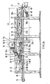
- a work surface 20 constituted here by a horizontal table (which will also be designated by the reference 20), near which there is a stock of containers 1 of several formats and a stock of objects to be packaged: unitary objects or lots grouped in any known manner, possibly with a label prepared with the recipient's contact details.
- the container-object assembly 1 of FIG. 6 is positioned against a rectilinear guide 21 secured to the work surface 20 and is thus faced with a reference plane 22 constituted by a smooth face of a profile placed on edge horizontally (and that will also be designated by reference 22).
- the work plane 20 and the reference plane 22 are therefore perpendicular to each other.
- the horizontal table 20 does not extend to the profile 22 because an endless chain 23 is provided whose upper strand is horizontal, located at the same level as the table 20 and movable parallel to the profile 22 as indicated by the arrow F4 .
- a ramp 24 is inclined from bottom to top towards the profile 22. Its lower edge 25 is at most at the same level as the table 20 but can without inconvenience be lower, and its upper edge 26 is in the reference plane 22. On Figure 6 we see that the lower edge 25 is located beyond the edge of the chain 23 closest to the profile 22 but in Figure 7 there is, intentionally, shown a variant according to which the lower edge 25 is above the upper strand of the chain 23.
- the ramp 24 could also be in bridge over the chain 23 to be connected to the table 20 but, as will be understood better below, the ramp 24 must be as little as possible projecting from the reference plane 22, even if it is movable so that the solution of FIG. 6 appears to be better than that of FIG. 7.
- the ramp 24 can be curved, concave, as shown, or even be flat, in an inclined plane.
- this segment 33 could also be curved like the spatula 28 of the element 27 and this spatula 28 could be rectilinear like segment 33, this is why we have voluntarily shown the two variants. The important thing is to have an oblique guide progressively connecting to the plane of the useful face of the element.
- the lateral face 34 of the pressure element 30 located opposite the reference plane 22 constitutes the useful face of said element 30 and this must be smooth, even slippery, flat and parallel to the reference plane 22.
- the pressure element 27 is connected to fixed parts of the frame of the machine by connecting rods 35 and 36 articulated on the element 27 by pivots 37 and 37 a and on the frame by pivots 38 and 38 a .
- These connecting rods 35 and 36 constitute with the element 27 an articulated parallelogram by which the element 27 can be raised and lowered while remaining parallel to itself.
- the pressure element 30 is connected to fixed parts of the frame of the machine by connecting rods 39 and 40 articulated on the element 30 by pivots 41 and 41 a and on the frame by pivots 42 and 42 a .
- These connecting rods 39 and 40 constitute, with the element 30, an articulated parallelogram by which the element 30 can deviate and approach the reference plane 22 while remaining parallel to itself.
- the operator chooses a container 1 in a given format, according to his appreciation of the object A to be packaged. He places it on the table 20 and straightens the side flaps 3 and 4. He places the object A on the base 2 then folds and flaps the flaps 3 and 4 then straightens, folds and flaps the flap 5 on the flaps 3 and 4 .
- the ramp 24 is fixed, it necessarily protrudes with respect to the reference plane 22. This can be accepted if the projection is weak and if the ramp 24 extends over a short length because then the container is placed in a slight oblique which does not harm following the operations. This obviously supposes that the containers 1 fold easily and that they are comparatively long with respect to the ramp 24.
- the ramp 24 must be relatively wide, if it must have a projection large enough to cause the containers to be folded correctly, it is advantageous to make the ramp 24 mobile so that it can disappear beyond the reference plane 22 .
- the container 1 is therefore in the position in FIG. 8: the base 2 rests on the work surface 20 and the external face of the closure panel 6 is pressed against the reference plane 22.
- the vertical pressure element 27 is in its lowest position and we place sacred here in the most probable situation considering that the container-object assembly 1 is higher than the useful bottom face 29 of this element ( figure 7).
- the container-object assembly 1 must be moved parallel to the reference plane 22, against it and always resting on the work plane 20. This movement is ensured by the chain 23 which carries from place to place cleats 23 has protruding, as is well known in itself.
- the starting of the chain 23 can be obtained in different ways: action of the operator on a contactor pedal, closing of a contactor by the ramp arriving in the erasing position, etc.
- This assembly simultaneously reaches, or according to a small offset, the spatula 28 of the vertical pressure element 27 and the oblique segment 33 of the horizontal pressure element 30.
- the vertical pressure element 27 extends a short distance from the profile 22 so that the closure panel 6 passes freely between them ( Figure 8).
- the element 27 carries a blade 49 at its active face 29 and placed on the side closest to the profile 22, so that it extends in the space which separates the side of the element. 27 and the profile 22.
- the blade 49 should not touch the profile 22 because it is intended to mark the material from which the closure panel 6 is made in order to create a line of weakness which should cause this panel 6 to be folded neatly at the exact level regardless of the height of the container-object assembly 1.
- the useful face 29 of the element 27 is necessarily applied to the highest part of the container-object assembly 1, that is to say on the external face of the flap 5, which is located at a level which varies with the thickness of the wrapped objects. Consequently, whatever this thickness, the useful face 29 is located on the flap 5 and the blade 49 is at this same level.
- closure panel 6 is marked by the blade 49, it can and must be folded down on the flap 5.
- the folding down of the panel 6 becomes an easy operation and known in itself.
- organs of any known type are provided: inclined ramp, presser, rollers, etc.
- rollers 50 and 51 which are offset both from top to bottom and in the direction of a bringing together of the center of the container.
- the profile of these rollers is adapted to the slope that must take the closure panel 6 under the effect of their lowering action.
- the panel 6 is vertical since the container-object assembly 1 has been pushed against the reference plane 22. It is necessary to bring it gradually to the horizontal and one can first of all provide a deflector (not shown) which initiates the inclination of the panel 6 to present it to the first roller 50 which is the highest and closest to the reference plane 22, that is to say the one furthest from the center of the container.
- a deflector not shown
- the roller 50 in turn lowers the panel a little more and presents it to the second roller 51 which is lower and further from the reference plane 22, that is to say closer to the center of the container.
- the machine comprises two vertical pressure elements and two horizontal pressure elements arranged in series in the upstream-downstream direction.
- the first pair element 27 of vertical pressure and element 30 of horizontal pressure must guide a single container-object assembly 1 since this assembly is held by these elements and until the closure panel 6 has received the marking by the slide 49 and the adhesive. Then, as said above, the panel 6 is folded down and the second couple then intervenes to guide the container-object assembly 1 to exert pressure for the time necessary for the setting of the adhesive.
- the second pair comprises a vertical pressure element 54 similar to the element 27 and which it is therefore unnecessary to describe again.
- the element 54 has a useful length L3 which is calculated as a function of the speed of movement of the chain 23 and of the nature of the adhesive placed on the panel 6 so that the pressure exerted vertically by the element 54 is exercised long enough to ensure correct bonding, that is to say to avoid any risk of accidental reopening on leaving the machine.
- the length L3 is indeed the useful length, not including the spatula 55 similar to the spatula 28 of the element 27, because the spatula 55 does not really exert pressure: it ensures the elevation of the element 54 when there is a container-object assembly 1 and contributes to applying the panel 6 to the flap 5.
- the real pressure having an action on the setting of the adhesive begins only beyond the spatula and it is from this place to measure the useful length L3.
- the connecting rods 56 and 57 are inclined so that at the time of the first contact with a container-object assembly 1, the element 54 tends to move in the same direction as it lifts in order to facilitate this lifting and progress of the container-object assembly 1.
- the spacing E must be such that the most advanced assembly 1 has reached its discharge point (right end of the machine on FIG. 16) at the latest when the next set 1 comes before the element 54. This means that the spacing E must take account of the greatest possible length for a set 1. In fact, the spacing E must be at least equal to the sum of L3 and of this greatest possible length.
- FIG. 17 the machine is seen in plan in the same situation as in FIG. 16. Just as it comprises two elements 27 and 54 of vertical pressure, it comprises two elements 30 and 60 of horizontal pressure similar to each other.
- the element 60 is returned to the standby position by two springs 61 and 62.
- the spring 61 is represented by a simple dotted line.
- the upstream end of the element 60 also has a straight and oblique "inlet" segment 63 to act as a ramp and cause the element 60 to move apart against the springs 61 and 62 when this occurs. a set 1.
- the element 60 is connected to the frame of the machine by connecting rods 64 and 65 articulated in parallelogram on the one hand to the element 60 by pivots 66 and 66 a and on the other hand to the frame of the machine by pivots 67 and 67 a . In this way, and just like the element 30, it remains parallel to itself during its spacing and approximation movements relative to the reference plane 22.
- FIG 5 there is shown in dotted lines a single ribbon 65 placed longitudinally in the middle of the container 1.
- a single ribbon 65 placed longitudinally in the middle of the container 1.
- Automatic devices capable of fitting such a tape exist and are not part of the present invention. With a machine according to the invention, such a device would be placed downstream of the pair of elements 27-30, after the closure panel 6 has been folded over the flap 5 and the latter have been temporarily held in good position.
- FIG. 5 another solution has also been shown which consists in placing two staples 66 and 67 on the sides of the container 1 because at this point the inner face of the flap 5 is accessible thanks to the presence of the sidewalks 7 and 8. It is therefore without particular difficulty to choose a stapling device from among those that exist and that the skilled person knows well. Such a device would be placed downstream of the pair of elements 27-30, after the closure panel 6 has been folded over the flap 5 and the latter have been temporarily held in good position.
- the pair of elements 54-60 may prove to be useless if the closed container 1 is evacuated immediately.
- the adhesive could equally be deposited on the exterior face of the shutter 5 (horizontal at the time of this operation) or on the interior face of the panel 6 (vertical at the time of this operation).
- the adhesive must be located correctly, whatever the level of the flap 5 dt whatever the format of the container 1, according to the dimensions of the object to be packaged A.
- a container 1 is seen from the side, which corresponds to the situation in FIG. 1, and the considerations that this figure and the following two illustrate are independent of the actual dimensions of this container 1.
- the container 1 is used for an object A whose thickness is such that the external face of the flap 5 is at a height H1 relative to the work surface 20.
- the container 1 is used for an object A whose thickness is such that the external face of the flap 5 is at a height H2 relative to the work surface 20.
- the useful face 29 of the element 27 will be applied against this face and will therefore also be at the height H1 or at the height H2.
- the adhesive deposition device were displaced in height as a direct function of the variations of the height H, it should rise when the height H increases and descend when it decreases.
- the element 27 applied against the flap 5 is shown diagrammatically by a vertical arrow F8 and supposed to give the level of the adhesive deposit, level shown diagrammatically by a horizontal arrow F9.
- the adhesive deposition device must be lowered when the height H increases and must be raised when the height H decreases, and this relative to the movements of the element 27.
- the result of these relative movements can also well be a real variation compared to the work plan 20 or only relative which could mean that the nozzle 72 has a movement compared to the element 27 but remains at the same level compared to the work plan 20.
- the machine according to the invention comprises a dispensing device adhesive 70 comprising a reservoir and provided with all the usual necessary accessories, including a power supply allowing the heating of the adhesive material and the operation of the desired components: pump, solenoid valves, etc.
- the reservoir receives a flexible conduit 71 leading to a nozzle 72 located opposite the path provided for the closure panels 6 of the containers.
- the nozzle 72 (or a rigid collar holding the flexible conduit 71) is fixed to an extension 73 of the connecting rod 35, disposed beyond the pivot 38, c that is to say upstream.
- the change in format of the containers 1 does not only concern their height as a function of the thickness of the objects to be packaged A (managed by the mobility of the elements 27 and 54) and their width (managed by the mobility of the elements 54 and 60) but also their length which is the direction of movement relative to the planes 20 and 22 and therefore the direction in which the adhesive must be deposited.
- closure panels 6 of the containers 1 all had the same dimensions, one could be satisfied with a contactor, possibly timed, to control the solenoid valve and thus cause the arrival of adhesive and its interruption. But, precisely, the problem posed here is insoluble with known means.
- the machine includes two contactors 80 and 81 controlling the solenoid valve. They are located to the right of the reference plane 22 (or possibly in the immediate vicinity) and are offset in the direction of movement of the containers on the machine, by the chain 23.
- the machine being designed for the implementation of the process according to the invention, which solves the problem of mechanization of the packaging in containers of different formats, it must accept containers so small that their length does not quickly reach the spatula 28 of the vertical pressure element 27.
- the dimensions of the containers are not randomly inhomogeneous and when one dimension (length or width) is small, the other (width or length) is too. This means that if a container is too short to quickly reach the element 27, its width is also small. This is why it is possible to provide a stop on the machine which is specifically designed for small containers.
- this stop 90 is provided projecting from the work surface 20 near the edge of the chain 23 and that it has the shape of an inclined plane. It is returned to this position, for example by means of a spring, and is erasable below said work surface 20 by simple pressure from top to bottom. This allows large containers 1 to pass unhindered over this stop 90 because its inclined plane shape forces it to sink into level 20 when a container reaches it from upstream to downstream.
- the container is of small format, its width practically does not exceed that of the chain 23 and is inscribed between the reference plane 22 and the useful face 91 of the stop 90, located vertically opposite the plane 22.
- An interesting application for the invention is that of postal items and this presupposes labeling.
- labels can be provided (possibly in an envelope also containing other documents such as delivery note, invoice, prospectus, order form, etc.) that are applied indifferently. on all container-object assemblies leaving the machine since, by hypothesis, all shipments are identical.
- the container-object sets are specific and care must therefore be taken to distinguish each one clearly.
- An economical and safe solution consists of providing a window in base 2 and placing a document against this base 2 revealing the recipient's coordinates through this window.
- the base 2 remains invariable in size and position during the entire treatment, unlike the flap 5 and especially the panel 6, so that the positioning of the chohsi document from the start is kept until the end.
- the finished package or package has the same appearance as that of FIG. 5, except for a few insignificant details.
- the method always consists of straightening the closure panel 6, then folding it over the top of the assembly 1 but instead of first straightening the panel 6 and then moving the container-object assembly, this recovery is carried out for move.
- the machine moreover, no longer has a ramp 24 disposed frontally opposite the work plane 20, and therefore below the reference plane 22.
- the latter is traversed by a slot 100 through which the panel can pass closing 6 when it is parallel to the work plane 20, the straightening of this panel 6 being carried out beyond the reference plane 22.
- the slot 100 has a sufficiently large height to allow free passage to the panel 6 without the operator needing to aim precisely. However, this height must also be low enough for a relatively thin assembly 1 to abut against the face of the reference plane adjacent to the work plane 20.
- the slot 100 is extended by a lower slot 101 which extends under the reference plane 22.
- the junction of the slots 100 and 101 determines an inclined stop 102 which allows the passage of the panels 6 in the slot 101 when they have the maximum authorized thickness and which, on the other hand, stops any set 1 too thick, which would be the case, for example, if a set 1 is badly engaged and / or badly displaced and takes an oblique position.
- This arrangement is very advantageous because it stops the assemblies 1 before they can reach the active members of the machine which will be described later.
- the stop by the stop 102 creates resistance to the advancement of the chain 23: the value of this resistance is calculated to control either an automatic stop of the chain 23 , either an alarm to attract the operator's attention, or any other action.
- the operator acts as described above, including by pushing the assembly 1 in the direction of the arrow F 7, but the closure panel 6 instead of meeting the ascending ramp 24 and straighten against the face of the plane 22 adjacent to the plane 20, passes through the slot 100 and extends beyond the reference plane 22.
- the assembly 1 abuts against the reference plane 22 by the edges of the flaps 3 and 4 ( Figure 28).
- a helical ramp 105 which extends parallel to the plane 22 in order to cause the straightening of the closure panel 6 during the movement of the assembly 1.
- the action of the ramp 105 can be supplemented by a second ramp, or guide, 106 located higher up and which completes the straightening of said panel 6.
- the assembly 1 being kept applied against the reference plane 22 by the pressure element 30, the closure panel 6 must bend properly in line with the edges of the flaps 3 and 4. However, it is safer to mark the material constituting the container 1 by creating a clean and strictly rectilinear fold line.
- a caster 108 driven by a motor 109 (or by a kinematic connection with a movable part of the machine such as a chain drive pinion 23), caster 108 which is located downstream of the stop 102 and upstream of the ramp 105 ( Figures 28 and 33).
- closure panel 6 When the closure panel 6 is in the vertical position, it must necessarily be placed against the "front" face of the reference plane 22, that is to say below and no longer beyond said plane 22.
- an opening 110 is arranged in the reference plane 22, the length of which depends on the slope of the ramps 105 and 106: the shorter the straightening of the closure panel 6, the more the opening 110 may be short, but the quality of the material used to make the containers 1 must be taken into account and may prohibit actions that are too brutal.
- the reference plane 22 has a cutaway 111 which ends in a vertical edge 112 thinned ( Figures 27 and 34).
- the nozzle 72 is located opposite the reference plane 22, downstream of the opening 110 considering the direction of movement of the assemblies 1, so that the closure panel 6 is stabilized, that is to say applied by its entire outer surface against said reference plane 22 ( Figures 30 and 35).
- lateral supports 115 are provided, located at the same level as the work surface 20 and above which the pressure elements 30 and 60 can move freely (FIGS. 27, 34 and 35).
- machines of the same type can be used for very different needs.
- the pressure elements 30 and 60 biased towards the reference plane 22 are associated with locking means which keep these elements 30 and 60 at a fixed distance from the reference plane 22.
- locking means which keep these elements 30 and 60 at a fixed distance from the reference plane 22.
- this variant has been illustrated by providing for each pressure element 30 and 60 two series of smooth holes respectively 120 and 121 made in the support 115 and distributed in two arcs of a circle centered on the pivots of the connecting rods of the elements 30 and 60.
- a tapped hole 122 is provided which is capable of receiving by threading the threaded rod 123 of a removable bolt 124.
- the element 60 is made integral with the fixed support 115.
- a hole 120-121 is necessarily at the base of a hole 122 of the element because the holes 120 and 121 were made according to the most common formats for the assemblies 1.
- the holes 120 and 121 are not necessarily equidistant since their spacing depends on the standardized or usual dimensions of the assemblies 1.
Landscapes
- Engineering & Computer Science (AREA)
- Mechanical Engineering (AREA)
- Closing Of Containers (AREA)
Applications Claiming Priority (2)
| Application Number | Priority Date | Filing Date | Title |
|---|---|---|---|
| FR8814214 | 1988-10-31 | ||
| FR8814214A FR2638423B1 (fr) | 1988-10-31 | 1988-10-31 | Procede pour l'emballage d'objets et machine pour la mise en oeuvre de ce procede |
Publications (1)
| Publication Number | Publication Date |
|---|---|
| EP0367674A1 true EP0367674A1 (de) | 1990-05-09 |
Family
ID=9371439
Family Applications (1)
| Application Number | Title | Priority Date | Filing Date |
|---|---|---|---|
| EP89403012A Withdrawn EP0367674A1 (de) | 1988-10-31 | 1989-10-31 | Verfahren zum Verpacken von Gegenständen und Maschine zur Durchführung des Verfahrens |
Country Status (3)
| Country | Link |
|---|---|
| EP (1) | EP0367674A1 (de) |
| CA (1) | CA2001841A1 (de) |
| FR (1) | FR2638423B1 (de) |
Cited By (1)
| Publication number | Priority date | Publication date | Assignee | Title |
|---|---|---|---|---|
| EP0657364A1 (de) * | 1993-12-07 | 1995-06-14 | Pussikeskus Oy | Verpackung für den Postversand und Verfahren zum Verpacken |
Citations (5)
| Publication number | Priority date | Publication date | Assignee | Title |
|---|---|---|---|---|
| DE1114433B (de) * | 1960-05-17 | 1961-09-28 | Carl Drohmann Ges Mit Beschrae | Einwickelmaschine fuer insbesondere prismatische Gegenstaende oder Stapel unterschiedlicher Formathoehe |
| US3213591A (en) * | 1964-10-28 | 1965-10-26 | Pemco Inc | Packaging and wrapping machine |
| GB1421782A (en) * | 1972-10-31 | 1976-01-21 | Gowater Packaging Ltd | Wrapping apparatus |
| EP0149351A2 (de) * | 1983-12-19 | 1985-07-24 | The Mead Corporation | Verpackungsmaschine und -verfahren |
| EP0273240A2 (de) * | 1986-12-17 | 1988-07-06 | JANHONEN, Veikko Ilmari | Apparat zum Falten und Schliessen eines aus Hüllmaterial bestehenden Abschnitts um einen zu verpackenden Artikel |
-
1988
- 1988-10-31 FR FR8814214A patent/FR2638423B1/fr not_active Expired - Fee Related
-
1989
- 1989-10-31 EP EP89403012A patent/EP0367674A1/de not_active Withdrawn
- 1989-10-31 CA CA 2001841 patent/CA2001841A1/fr not_active Abandoned
Patent Citations (5)
| Publication number | Priority date | Publication date | Assignee | Title |
|---|---|---|---|---|
| DE1114433B (de) * | 1960-05-17 | 1961-09-28 | Carl Drohmann Ges Mit Beschrae | Einwickelmaschine fuer insbesondere prismatische Gegenstaende oder Stapel unterschiedlicher Formathoehe |
| US3213591A (en) * | 1964-10-28 | 1965-10-26 | Pemco Inc | Packaging and wrapping machine |
| GB1421782A (en) * | 1972-10-31 | 1976-01-21 | Gowater Packaging Ltd | Wrapping apparatus |
| EP0149351A2 (de) * | 1983-12-19 | 1985-07-24 | The Mead Corporation | Verpackungsmaschine und -verfahren |
| EP0273240A2 (de) * | 1986-12-17 | 1988-07-06 | JANHONEN, Veikko Ilmari | Apparat zum Falten und Schliessen eines aus Hüllmaterial bestehenden Abschnitts um einen zu verpackenden Artikel |
Cited By (1)
| Publication number | Priority date | Publication date | Assignee | Title |
|---|---|---|---|---|
| EP0657364A1 (de) * | 1993-12-07 | 1995-06-14 | Pussikeskus Oy | Verpackung für den Postversand und Verfahren zum Verpacken |
Also Published As
| Publication number | Publication date |
|---|---|
| FR2638423B1 (fr) | 1991-01-25 |
| CA2001841A1 (fr) | 1990-04-30 |
| FR2638423A1 (fr) | 1990-05-04 |
Similar Documents
| Publication | Publication Date | Title |
|---|---|---|
| EP0295203B1 (de) | Verfahren zum Verpacken eines Produkts und Vorrichtung zur Ausübung des Verfahrens | |
| FR2927015A1 (fr) | Procede et dispositif pour la realisation de boites a partir d'un ensemble de decoupes | |
| CA2004409C (fr) | Machine, notamment encartonneuse, pour mettre automatiquement un article, en particulier un flacon, dans un etui | |
| LU83746A1 (fr) | Procede et appareil d'emballage de rouleaux avec dispositif d'insertion d'etiquettes | |
| FR2490182A1 (fr) | Machine pour la fermeture des volets superieurs de boites parallelepipediques a volets rabattables | |
| FR2655947A1 (fr) | Dispositif pour l'application de bandes a des paquets sensiblement parallelepipediques. | |
| FR2898072A1 (fr) | Procede et dispositif pour la realisation d'un emballage en carton de volume variable | |
| EP0560699B1 (de) | Automatische Vorrichtung zum kontinuierlichen Anbringen von selbstklebenden Handgriffen | |
| FR3057204A1 (fr) | Machine pour la production de recipients en boite a fond et/ou couvercle composes d'une base semblable a un disque et d'une surface laterale definie par une bande ou ceinture raccordee au perimetre de la base semblable a un disque | |
| EP0893241A1 (de) | Verfahren und vorrichtung zum automatischen verkleben einer wärmeschrumpfenden kunststoff-folie auf den boden einer offenen kiste. | |
| EP0367674A1 (de) | Verfahren zum Verpacken von Gegenständen und Maschine zur Durchführung des Verfahrens | |
| EP0000451B1 (de) | Klemme zum Festhalten von Gegenständen, Vorrichtung zum Anhängen zum Abhängen und zum Überlappen einer derartigen Klemme, und Anwendung dieser Klemme dieser Vorrichtung in Behandlungsanlagen | |
| EP0004631B1 (de) | Verpackungsvorrichtung und -verfahren | |
| FR3038887A1 (fr) | Machine de pliage de carton d'emballage et carton d'emballage adapte | |
| FR2604654A1 (fr) | Machine pour la fabrication d'emballage de produits sous feuilles retractables | |
| EP0204606B1 (de) | Vorrichtung zum Aufrichten, Füllen und Palettisieren von Behältern | |
| FR2661392A1 (fr) | Procede pour le conditionnement de lots de produits de volumes divers, dispositif pour la mise en óoeuvre de ce procede et conditionnement ainsi obtenu. | |
| EP0151364A2 (de) | Verpackungsstrasse für Produkte mit einem Film in einem aus einem flachen vorgeschnittenen Zuschnitt hergestellten Behälter | |
| FR2494213A1 (fr) | Dispositif pour emballer des piles de papier dans des cartons preformes | |
| EP0900737A1 (de) | Vorrichtung zum Aufbringen und Perforieren eines biegsamen Versteifungs- und/oder Führungsbandes, Verfahren und auf diese Weise hergestellter Verpackungsbehälter | |
| FR2770447A1 (fr) | Procede et machine a barillet pour la mise en volume d'une caisse tambour munie d'un film retractable a partir de decoupes en carton | |
| WO2021069637A1 (fr) | Dispositif et procede de formage de conteneur par pliage | |
| EP0052057B1 (de) | Verfahren und Vorrichtung zum Überziehen einer Ladung mit einer Schlauchfolie | |
| FR2940260A1 (fr) | Dispositif de traitement d'au moins une liasse d'articles souples dote d'au moins un deliasseur | |
| FR2616747A1 (fr) | Machine automatique de preformage, de remplissage et de fermeture de coffrets livres plies a plat et coffret mis en oeuvre sur une telle machine |
Legal Events
| Date | Code | Title | Description |
|---|---|---|---|
| PUAI | Public reference made under article 153(3) epc to a published international application that has entered the european phase |
Free format text: ORIGINAL CODE: 0009012 |
|
| AK | Designated contracting states |
Kind code of ref document: A1 Designated state(s): AT BE CH DE ES FR GB GR IT LI LU NL SE |
|
| 17P | Request for examination filed |
Effective date: 19901211 |
|
| 17Q | First examination report despatched |
Effective date: 19920227 |
|
| STAA | Information on the status of an ep patent application or granted ep patent |
Free format text: STATUS: THE APPLICATION IS DEEMED TO BE WITHDRAWN |
|
| 18D | Application deemed to be withdrawn |
Effective date: 19931204 |