EP0367394B1 - Feuersperre - Google Patents
Feuersperre Download PDFInfo
- Publication number
- EP0367394B1 EP0367394B1 EP89309449A EP89309449A EP0367394B1 EP 0367394 B1 EP0367394 B1 EP 0367394B1 EP 89309449 A EP89309449 A EP 89309449A EP 89309449 A EP89309449 A EP 89309449A EP 0367394 B1 EP0367394 B1 EP 0367394B1
- Authority
- EP
- European Patent Office
- Prior art keywords
- plates
- flame trap
- flame
- blades
- trap
- Prior art date
- Legal status (The legal status is an assumption and is not a legal conclusion. Google has not performed a legal analysis and makes no representation as to the accuracy of the status listed.)
- Expired - Lifetime
Links
- 238000007789 sealing Methods 0.000 claims description 19
- 239000010935 stainless steel Substances 0.000 claims description 6
- 229910001220 stainless steel Inorganic materials 0.000 claims description 6
- RYGMFSIKBFXOCR-UHFFFAOYSA-N Copper Chemical compound [Cu] RYGMFSIKBFXOCR-UHFFFAOYSA-N 0.000 claims description 4
- 239000010949 copper Substances 0.000 claims description 4
- 229910052802 copper Inorganic materials 0.000 claims description 4
- 229910045601 alloy Inorganic materials 0.000 claims description 3
- 239000000956 alloy Substances 0.000 claims description 3
- 230000002093 peripheral effect Effects 0.000 claims description 2
- 238000004049 embossing Methods 0.000 claims 2
- 230000001419 dependent effect Effects 0.000 claims 1
- 239000007789 gas Substances 0.000 abstract description 11
- 238000004140 cleaning Methods 0.000 abstract description 7
- OKTJSMMVPCPJKN-UHFFFAOYSA-N Carbon Chemical compound [C] OKTJSMMVPCPJKN-UHFFFAOYSA-N 0.000 abstract description 2
- 229910052799 carbon Inorganic materials 0.000 abstract description 2
- 238000002485 combustion reaction Methods 0.000 abstract description 2
- 125000006850 spacer group Chemical group 0.000 description 10
- 230000004888 barrier function Effects 0.000 description 3
- 229910001369 Brass Inorganic materials 0.000 description 2
- 229910000570 Cupronickel Inorganic materials 0.000 description 2
- 239000002956 ash Substances 0.000 description 2
- 239000010951 brass Substances 0.000 description 2
- 231100001261 hazardous Toxicity 0.000 description 2
- UGFAIRIUMAVXCW-UHFFFAOYSA-N Carbon monoxide Chemical compound [O+]#[C-] UGFAIRIUMAVXCW-UHFFFAOYSA-N 0.000 description 1
- 238000005452 bending Methods 0.000 description 1
- 229910052790 beryllium Inorganic materials 0.000 description 1
- ATBAMAFKBVZNFJ-UHFFFAOYSA-N beryllium atom Chemical compound [Be] ATBAMAFKBVZNFJ-UHFFFAOYSA-N 0.000 description 1
- DMFGNRRURHSENX-UHFFFAOYSA-N beryllium copper Chemical compound [Be].[Cu] DMFGNRRURHSENX-UHFFFAOYSA-N 0.000 description 1
- 238000010276 construction Methods 0.000 description 1
- 230000000694 effects Effects 0.000 description 1
- 239000003546 flue gas Substances 0.000 description 1
- 239000010881 fly ash Substances 0.000 description 1
- 239000010687 lubricating oil Substances 0.000 description 1
- 239000000463 material Substances 0.000 description 1
- 238000012856 packing Methods 0.000 description 1
- 239000002245 particle Substances 0.000 description 1
- 238000011144 upstream manufacturing Methods 0.000 description 1
Images

Classifications
-
- A—HUMAN NECESSITIES
- A62—LIFE-SAVING; FIRE-FIGHTING
- A62C—FIRE-FIGHTING
- A62C4/00—Flame traps allowing passage of gas but not of flame or explosion wave
- A62C4/02—Flame traps allowing passage of gas but not of flame or explosion wave in gas-pipes
Definitions
- the present invention relates to flame traps and particularly to self cleaning flame traps.
- a flame trap generally consists of a plurality of closely spaced and rigidly fixed plates which together act as a barrier for flame while nevertheless allowing the passage of gas. They may typically be positioned in pipes or ducts along which it is important that a flame cannot propagate. A typical example is in the exhaust line of a diesel engine operating in a hazardous or potentially hazardous atmosphere.
- a known flame trap comprises a housing, a plurality of generally parallel spaced plates, defining passageways for gases in the housing, and wiper means arranged to remove deposits from between the plates.
- a further disadvantage is that since the deposits tend to build up only on the leading edge of the plates, (that is, on the edge of the plates facing upstream with respect to the flow of gas) the plates tend to become disproportionately quickly coated along this edge and therefore need to be cleaned relatively more frequently.
- GB 1058004 discloses a fly ash arrestor for an incinerator in which a rotatable perforated drum is located in the path of a flue gas. The gas passes through the perforations while a proportion of the ash is deposited on the periphery of the drum. Scraper blades are positioned to remove the ash deposits from the side of the drum as it is rotated.
- the present invention is characterised in that the plates are arranged for rotation about an axis to move relative to the wiper means to remove the deposits.
- the wiper means are preferably fixed against rotation, and may be mounted on a fixed housing or on a support post. They may, however, be adjustable or self-adjusting.
- the projection of the wipers may be offset with respect to the axis of rotation of the plates.
- the plates are desirably circular and are keyed to a rotatable axle by which they may be driven.
- the axle may have a non circular, for example a square, cross section.
- the plates are thus arranged to rotate together as a unit. They may be spaced apart by intermediate spacers, separate from the plates, or by bosses on or secured to each plate. The bosses may be stamped or embossed into the surface of each plate.
- Each plate preferably has a pair of bosses diametrically spaced. The adjacent plates may have their bosses angularly staggered.
- the wipers may comprise elongate blades, interleaved between the plates, and preferably extending outside the circumference of the plates.
- the blades may be secured together outside the edge of the rotating plates, for example by means of a plurality of intermediate spacers and a securing spindle passing through the blades and spacers.
- Each of the blades may further be provided with an aperture at an end between the rotating plates, with the axle to which the plates are keyed passing through this aperture.
- the blades need not be themselves spaced on their own shaft. In this case, their positions are maintained by the fact that they are interleaved between the moving plates. They are self adjustably free to move on the shaft.
- the blades are positioned downstream of the axle (and of course of the leading edges of the plates) so that any deposits removed from the plates will be free to blow away.
- the air flow through the flame trap may be between the plates and perpendicular to the axis of rotation. Sealing means may be provided on opposing sides of the axis to provide a conduit along which the air flow must pass to ensure that substantially all of the air flow passes between the parallel plates.
- the sealing means may comprise a barrier having a part-cylindrical inner surface which fits sufficiently closely against the peripheral edges of the plates to prevent any flames from passing.
- the sealing means could be instead a plurality of stacked packers, with alternate packers extending into the space between adjacent plates. These packers could conveniently be constructed out of a stack of alternately larger and smaller rectangular flat packing plates or alternatively radiused plates sealing against the edge of an adjacent plate and large rectangular stacking plates extending between the rotating plates.
- a further possibility would be to use a single slotted plate, placed generally parallel to the axis of rotation, and having fingers (in a manner of a comb) extending into the spaces between adjacent plates.
- Another possibility is to pass wires through the plates at the periphery and to thread these into the side wall of the flame trap housing to close gaps at the edges.
- the rotating plates could be annular with the air flow being arranged to pass first between the plates and then along a central conduit, axially of the stack of plates; or instead the air flow could be in the opposite direction, axially and then outwardly between adjacent plates. In the latter case, it would be desirable to provide wiper means which extend over the inner circumferential edge of the plates.
- wiper means which extend over the inner circumferential edge of the plates.
- the plates are approximately 1.26 millimetres thick, and are spaced apart by about 0.5 millimetres.
- the wiper blades have a thickness of about 0.4 millimetres or even less in some circumstances.
- the flame trap shown in Figure 1 to 3 comprises a stack of closely spaced stainless steel plates 10 mounted for rotation as a unit about a common vertical axis.
- the plates may either be interleaved with a plurality of spacers 12 on a common central axle 14, or they may alternatively each carry an integral embossed or welded boss in place of the spacer 12 to provide for the appropriate spacing.
- the axle 14 is desirably of a square cross section to allow the blades to be positively rotated by means of a motor or other means (not shown) arranged to cause rotation of the axle.
- the blades Interleaved between the rotating plates 10 there are a plurality of fixed elongate wiper blades 18.
- the blades have one tapered end 20, having a tapered leading edge 23 confronting the plates as they rotate, and a generally rectangular other end 22 which extends beyond the circumference of the plates 10.
- the rectangular ends 22 may be secured together, by means of a square section retaining post 26 which passes through the interdigitated blades and spacers.
- the blades are self-adjusting, being free to move along the post. Their respective positions being determined by being spaced by the plates 10.
- the blades, together with intermediate spacers 25, are pinned together by means of a spindle 26A.
- the axis of the spindle 26A or post 26 is offset with respect to the axis of the axle 14, i.e. shifted normally with respect to the direction of flow indicated by the arrows 24.
- FIG. 1 an alternate form of blade shape is illustrated.
- the blade 18A extends across the axle 14.
- the end 20A is rounded and is formed with an opening 21 to accommodate the axle 14.
- the opening 21 is larger than the spacer 12, so that the plate can rotate relative to the wiper blade.
- the stack of plates on the axle 14 can be tightened up without at the same time substantially increasing the friction between the rotating plates and the stationary blades.
- the thickness of the blades will be slightly less than the spacing between the plates.
- these spacers 12 are not essential. The relative positions of the blades can otherwise be maintained by being supported by the plates as mentioned previously.
- sealing means are provided so as to provide a defined air flow passage, in the direction of the air flow 24, generally parallel to the wiper blades 18 and between the plates.
- the plates and blades are mounted on a housing constituted in part by the sealing means.
- the sealing means comprise an interleaved stack of alternately radiused plates 27 shaped to the circumference of an adjacent plate 10 and rectangular plates 27A extending between the plates 27.
- the radiused plates 27 are a close tolerance match to the rotating plates 10 to provide a seal.
- the rectangular plates 27A create an additional flame barrier to enhance the flame sealing of the radiused plates 27.
- the sealing means may take the form shown on the right of Figure 3: which is a cylindrical housing 28.
- edge sealing is provided by a part-cylindrical member 36, the surface of which, as may be seen in figure 2, fits closely to the edge of the plates 10.
- the spacing between the surface and the edges of the plates are sufficiently small to prevent the passage of flames.
- Additional stops 38 are provided above the uppermost plate, and below the lowermost plate.
- the blades are preferably made of stainless steel or a copper based alloy, such as beryllium/copper, brass or cupro-nickel.
- the plates are preferably made of stainless steel.
- the plates 10 are slowly rotated continuously or intermittently on the axle 14 at a rate of about one revolution per minute. Deposits building up on the edge of the plate will tend to be broken up at the point X ( Figure 2), and the broken up deposits blown downstream and away from the flame trap. Since the plates are rotating the deposits will tend to build up equally around all points of the circumference, thus prolonging plate life.
- a plurality of fingers 40 extending into the gap between the plates, to assist in initially breaking up the deposits.
- these fingers 40 are shown at their preferred location for an anticlockwise rotation of the plates. It will be appreciated, of course, that they could also be positioned elsewhere about the circumference, and that it may be desirable in certain circumstances to provide these fingers at more than one location.
- the fingers could either be individual or, more conveniently, they could be formed by cutting a plurality of slots out of the plate, in the manner of a comb.
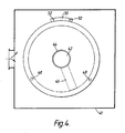
- the air flow may pass not straight across the plates, as indicated by the arrows 24, but instead first into the space between the plates from all sides of the housing 41 and then out along a conduit defined by a large central aperture 42 in each plate 10, the end of this aperture communicates with a fixed central conduit 44 at one end.
- the gas flow may pass in the opposite direction: that is, first along the conduit and then out between the rotating plates.
- the wiper blades may overlap to some extent the edge of the plate 10 which is first encountered by the gas flow, so that the deposits forming on that edge may be efficiently removed.
- the blades 46 are truncated short of the circumference of the plates.
- the moving gases will tend to permit only a small build up of deposits on the outer edge of the plates before the errosive effects of the particle laden gases limit the build up to a tolerable level.
- the top plate opposite the central conduit 44, is blanked off and secured to a central drive shaft (not shown) by which the plates are rotated.
- a central drive shaft not shown
- the plates may alternatively be pinned using short webs 50 formed on the plates through which pins 52 hold them together in their angular relationship.
- the plates are pinned together through webs extending radially inwardly, into the central aperture 42.
- the blades have to be mounted on the outside of the plates as previously described.
- the flame arrestor does not increase the back pressure in the exhaust any more than is absolutely necessary.
- the use of radially out pinning is preferred.
- This annular form of flame trap is found to be particularly efficient as it avoids the sealing problems in defining the flow path previously described as the flow is simply directed to or from the entire periphery of the plates.
- the plates 10 are about 1.25 millimetres thick, and are spaced apart by about 0.5 millimetres.
- the wiper blades 18 are about 0.4 millimetres thick.
- wiper blades are copper-based alloys, such as, beryllium-copper, brass or cupro-nickel. Alternatively stainless steel can be used.
- the drive shaft of the flame trap can be connected by a belt to the fan drive at the front of an engine to provide continuous movement.
- other sources of motive power can be exploited.
- an intermittent hydraulic drive can be used.
- the purpose of the drive can be to achieve a reciprocating motion which can be connected up to the axle 14 of the flame trap in a conventional manner to provide an intermittent drive or "inching" motion.
- the flame trap requires a device for converting the rotary motion to a reciprocating motion that can be used to move a ratchet arrangement.
- the reciprocating motion can be derived from an eccentric, as will be known to the skilled person.
- the inching intermittent motion can be derived using a oneway roller or Sprague clutch. For example as manufactured by Torrington Company Limited of Grovelands Industrial Estate, Longford Road, Exhall, Coventry, England under the serial number FCB 30.
Landscapes
- Health & Medical Sciences (AREA)
- Public Health (AREA)
- Business, Economics & Management (AREA)
- Emergency Management (AREA)
- Separating Particles In Gases By Inertia (AREA)
- Catching Or Destruction (AREA)
- Fire-Extinguishing Compositions (AREA)
- Transition And Organic Metals Composition Catalysts For Addition Polymerization (AREA)
- Polyesters Or Polycarbonates (AREA)
- Control And Other Processes For Unpacking Of Materials (AREA)
- Incineration Of Waste (AREA)
Claims (23)
Priority Applications (1)
| Application Number | Priority Date | Filing Date | Title |
|---|---|---|---|
| AT89309449T ATE65924T1 (de) | 1988-11-04 | 1989-09-18 | Feuersperre. |
Applications Claiming Priority (2)
| Application Number | Priority Date | Filing Date | Title |
|---|---|---|---|
| GB8825823 | 1988-11-04 | ||
| GB888825823A GB8825823D0 (en) | 1988-11-04 | 1988-11-04 | Flame trap |
Publications (2)
| Publication Number | Publication Date |
|---|---|
| EP0367394A1 EP0367394A1 (de) | 1990-05-09 |
| EP0367394B1 true EP0367394B1 (de) | 1991-08-07 |
Family
ID=10646302
Family Applications (1)
| Application Number | Title | Priority Date | Filing Date |
|---|---|---|---|
| EP89309449A Expired - Lifetime EP0367394B1 (de) | 1988-11-04 | 1989-09-18 | Feuersperre |
Country Status (5)
| Country | Link |
|---|---|
| EP (1) | EP0367394B1 (de) |
| AT (1) | ATE65924T1 (de) |
| DE (1) | DE68900190D1 (de) |
| ES (1) | ES2023524B3 (de) |
| GB (1) | GB8825823D0 (de) |
Families Citing this family (1)
| Publication number | Priority date | Publication date | Assignee | Title |
|---|---|---|---|---|
| CN111111052A (zh) * | 2020-01-19 | 2020-05-08 | 江苏福茂环保科技有限公司 | 一种免清洗的阻火器 |
Family Cites Families (3)
| Publication number | Priority date | Publication date | Assignee | Title |
|---|---|---|---|---|
| GB1058004A (en) * | 1964-10-21 | 1967-02-08 | Kenneth Richardson Morton | Rotary burnt paper and fly ash arrestor |
| US4307673A (en) * | 1979-07-23 | 1981-12-29 | Forest Fuels, Inc. | Spark arresting module |
| GB2183020B (en) * | 1985-11-14 | 1989-10-11 | Barnes Ecas Limited | A flame arrestor |
-
1988
- 1988-11-04 GB GB888825823A patent/GB8825823D0/en active Pending
-
1989
- 1989-09-18 AT AT89309449T patent/ATE65924T1/de active
- 1989-09-18 DE DE8989309449T patent/DE68900190D1/de not_active Expired - Fee Related
- 1989-09-18 EP EP89309449A patent/EP0367394B1/de not_active Expired - Lifetime
- 1989-09-18 ES ES89309449T patent/ES2023524B3/es not_active Expired - Lifetime
Also Published As
| Publication number | Publication date |
|---|---|
| ES2023524B3 (es) | 1992-01-16 |
| ATE65924T1 (de) | 1991-08-15 |
| EP0367394A1 (de) | 1990-05-09 |
| GB8825823D0 (en) | 1988-12-07 |
| DE68900190D1 (de) | 1991-09-12 |
Similar Documents
| Publication | Publication Date | Title |
|---|---|---|
| US4268205A (en) | Method and apparatus for removing material from the ends of a rotary air lock | |
| CN1041282C (zh) | 具有非平行分离通道的转动粒子分离器和一种分离设备 | |
| CA2918467C (en) | Systems and methods for removing particulate matter from exhaust gas streams | |
| ZA200100150B (en) | High affinity ligands for nociceptin receptor ORL-1. | |
| CN1289266A (zh) | 螺杆转鼓式过滤器 | |
| EP0367394B1 (de) | Feuersperre | |
| US4706454A (en) | Vehicle anti-pollution exhaust device | |
| EP0492770A1 (de) | Lüfter | |
| JPH0367654A (ja) | ダスト除去装置 | |
| US3701237A (en) | Smoke eliminator | |
| GB2183020A (en) | A flame arrestor | |
| CA1058119A (en) | Rotary feeder | |
| US4993940A (en) | Scraper for an axial seal in a rotary combustor | |
| EP3641916A1 (de) | Scr-system zum entfernen von asche aus einem in einer verbrennungsanlage erzeugten rauchgasstrom | |
| CN112512697A (zh) | 用于净化载有颗粒的气态介质的装置 | |
| KR20220119849A (ko) | 스파크 어레스터 | |
| SU762938A1 (ru) | Фильтр для очистки газов1 | |
| WO1995032392A1 (en) | Grate | |
| RU2131292C1 (ru) | Устройство для очистки запыленных газов | |
| US4042355A (en) | Pollution control device | |
| CN213120144U (zh) | 一种可脱硝的耐高温材料工业窑炉 | |
| GB2483904A (en) | Flame arrester | |
| JPS589618Y2 (ja) | 排ガスへの粉末薬品吹込み装置 | |
| RU2753111C2 (ru) | Лопастной осерадиальный сепаратор | |
| JPWO2020126551A5 (de) |
Legal Events
| Date | Code | Title | Description |
|---|---|---|---|
| PUAI | Public reference made under article 153(3) epc to a published international application that has entered the european phase |
Free format text: ORIGINAL CODE: 0009012 |
|
| AK | Designated contracting states |
Kind code of ref document: A1 Designated state(s): AT BE CH DE ES FR GB GR IT LI LU NL SE |
|
| 17P | Request for examination filed |
Effective date: 19900420 |
|
| 17Q | First examination report despatched |
Effective date: 19900803 |
|
| ITF | It: translation for a ep patent filed | ||
| GRAA | (expected) grant |
Free format text: ORIGINAL CODE: 0009210 |
|
| AK | Designated contracting states |
Kind code of ref document: B1 Designated state(s): AT BE CH DE ES FR GB GR IT LI LU NL SE |
|
| PG25 | Lapsed in a contracting state [announced via postgrant information from national office to epo] |
Ref country code: SE Effective date: 19910807 Ref country code: LI Effective date: 19910807 Ref country code: GR Free format text: LAPSE BECAUSE OF FAILURE TO SUBMIT A TRANSLATION OF THE DESCRIPTION OR TO PAY THE FEE WITHIN THE PRESCRIBED TIME-LIMIT Effective date: 19910807 Ref country code: CH Effective date: 19910807 Ref country code: AT Effective date: 19910807 |
|
| REF | Corresponds to: |
Ref document number: 65924 Country of ref document: AT Date of ref document: 19910815 Kind code of ref document: T |
|
| PGFP | Annual fee paid to national office [announced via postgrant information from national office to epo] |
Ref country code: ES Payment date: 19910902 Year of fee payment: 3 |
|
| PGFP | Annual fee paid to national office [announced via postgrant information from national office to epo] |
Ref country code: FR Payment date: 19910906 Year of fee payment: 3 |
|
| REF | Corresponds to: |
Ref document number: 68900190 Country of ref document: DE Date of ref document: 19910912 |
|
| PG25 | Lapsed in a contracting state [announced via postgrant information from national office to epo] |
Ref country code: LU Free format text: LAPSE BECAUSE OF NON-PAYMENT OF DUE FEES Effective date: 19910930 |
|
| PGFP | Annual fee paid to national office [announced via postgrant information from national office to epo] |
Ref country code: NL Payment date: 19910930 Year of fee payment: 3 Ref country code: DE Payment date: 19910930 Year of fee payment: 3 |
|
| ET | Fr: translation filed | ||
| PGFP | Annual fee paid to national office [announced via postgrant information from national office to epo] |
Ref country code: BE Payment date: 19911106 Year of fee payment: 3 |
|
| REG | Reference to a national code |
Ref country code: CH Ref legal event code: PL |
|
| REG | Reference to a national code |
Ref country code: ES Ref legal event code: FG2A Ref document number: 2023524 Country of ref document: ES Kind code of ref document: B3 |
|
| PLBE | No opposition filed within time limit |
Free format text: ORIGINAL CODE: 0009261 |
|
| STAA | Information on the status of an ep patent application or granted ep patent |
Free format text: STATUS: NO OPPOSITION FILED WITHIN TIME LIMIT |
|
| 26N | No opposition filed | ||
| PG25 | Lapsed in a contracting state [announced via postgrant information from national office to epo] |
Ref country code: ES Free format text: LAPSE BECAUSE OF THE APPLICANT RENOUNCES Effective date: 19920919 |
|
| PG25 | Lapsed in a contracting state [announced via postgrant information from national office to epo] |
Ref country code: BE Effective date: 19920930 |
|
| BERE | Be: lapsed |
Owner name: PYROBAN LTD Effective date: 19920930 |
|
| PG25 | Lapsed in a contracting state [announced via postgrant information from national office to epo] |
Ref country code: NL Effective date: 19930401 |
|
| NLV4 | Nl: lapsed or anulled due to non-payment of the annual fee | ||
| PG25 | Lapsed in a contracting state [announced via postgrant information from national office to epo] |
Ref country code: FR Effective date: 19930528 |
|
| PG25 | Lapsed in a contracting state [announced via postgrant information from national office to epo] |
Ref country code: DE Effective date: 19930602 |
|
| REG | Reference to a national code |
Ref country code: FR Ref legal event code: ST |
|
| PGFP | Annual fee paid to national office [announced via postgrant information from national office to epo] |
Ref country code: GB Payment date: 19931101 Year of fee payment: 5 |
|
| PG25 | Lapsed in a contracting state [announced via postgrant information from national office to epo] |
Ref country code: GB Effective date: 19940918 |
|
| GBPC | Gb: european patent ceased through non-payment of renewal fee |
Effective date: 19940918 |
|
| REG | Reference to a national code |
Ref country code: ES Ref legal event code: FD2A Effective date: 19991007 |
|
| PG25 | Lapsed in a contracting state [announced via postgrant information from national office to epo] |
Ref country code: IT Free format text: LAPSE BECAUSE OF NON-PAYMENT OF DUE FEES Effective date: 20050918 |