EP0367100B1 - Ventil mit pneumatischer Betätigung - Google Patents
Ventil mit pneumatischer Betätigung Download PDFInfo
- Publication number
- EP0367100B1 EP0367100B1 EP19890119874 EP89119874A EP0367100B1 EP 0367100 B1 EP0367100 B1 EP 0367100B1 EP 19890119874 EP19890119874 EP 19890119874 EP 89119874 A EP89119874 A EP 89119874A EP 0367100 B1 EP0367100 B1 EP 0367100B1
- Authority
- EP
- European Patent Office
- Prior art keywords
- duct
- straight
- valves
- valve
- fact
- Prior art date
- Legal status (The legal status is an assumption and is not a legal conclusion. Google has not performed a legal analysis and makes no representation as to the accuracy of the status listed.)
- Expired - Lifetime
Links
Images

Classifications
-
- B—PERFORMING OPERATIONS; TRANSPORTING
- B60—VEHICLES IN GENERAL
- B60P—VEHICLES ADAPTED FOR LOAD TRANSPORTATION OR TO TRANSPORT, TO CARRY, OR TO COMPRISE SPECIAL LOADS OR OBJECTS
- B60P3/00—Vehicles adapted to transport, to carry or to comprise special loads or objects
- B60P3/22—Tank vehicles
- B60P3/224—Tank vehicles comprising auxiliary devices, e.g. for unloading or level indicating
- B60P3/225—Adaptations for pumps or valves
-
- F—MECHANICAL ENGINEERING; LIGHTING; HEATING; WEAPONS; BLASTING
- F16—ENGINEERING ELEMENTS AND UNITS; GENERAL MEASURES FOR PRODUCING AND MAINTAINING EFFECTIVE FUNCTIONING OF MACHINES OR INSTALLATIONS; THERMAL INSULATION IN GENERAL
- F16K—VALVES; TAPS; COCKS; ACTUATING-FLOATS; DEVICES FOR VENTING OR AERATING
- F16K11/00—Multiple-way valves, e.g. mixing valves; Pipe fittings incorporating such valves
- F16K11/10—Multiple-way valves, e.g. mixing valves; Pipe fittings incorporating such valves with two or more closure members not moving as a unit
- F16K11/20—Multiple-way valves, e.g. mixing valves; Pipe fittings incorporating such valves with two or more closure members not moving as a unit operated by separate actuating members
- F16K11/22—Multiple-way valves, e.g. mixing valves; Pipe fittings incorporating such valves with two or more closure members not moving as a unit operated by separate actuating members with an actuating member for each valve, e.g. interconnected to form multiple-way valves
-
- F—MECHANICAL ENGINEERING; LIGHTING; HEATING; WEAPONS; BLASTING
- F16—ENGINEERING ELEMENTS AND UNITS; GENERAL MEASURES FOR PRODUCING AND MAINTAINING EFFECTIVE FUNCTIONING OF MACHINES OR INSTALLATIONS; THERMAL INSULATION IN GENERAL
- F16K—VALVES; TAPS; COCKS; ACTUATING-FLOATS; DEVICES FOR VENTING OR AERATING
- F16K27/00—Construction of housing; Use of materials therefor
- F16K27/003—Housing formed from a plurality of the same valve elements
-
- F—MECHANICAL ENGINEERING; LIGHTING; HEATING; WEAPONS; BLASTING
- F16—ENGINEERING ELEMENTS AND UNITS; GENERAL MEASURES FOR PRODUCING AND MAINTAINING EFFECTIVE FUNCTIONING OF MACHINES OR INSTALLATIONS; THERMAL INSULATION IN GENERAL
- F16K—VALVES; TAPS; COCKS; ACTUATING-FLOATS; DEVICES FOR VENTING OR AERATING
- F16K27/00—Construction of housing; Use of materials therefor
- F16K27/07—Construction of housing; Use of materials therefor of cutting-off parts of tanks, e.g. tank-cars
Definitions
- the present invention relates to a modular pneumatically operated valve, applicable in particular to the equipment of tanks with compartments mounted on a vehicle.
- French patent FR-A-2 145 858 discloses a manifold for dispensing or taking up pressurized fluids, applicable in particular to compressed air and composed of a removable assembly of parallelepipedic bodies aligned by lateral faces. Each element constitutes an individual valve comprising conduits and valves intended to establish and cut communications between them, one of the conduits being straight and passing right through between two opposite faces. Despite the compactness and flexibility of operation of such a manifold, it nevertheless constitutes only an assembly of valves, unitary to a channel and with manual control which, for example, could not be applied directly to the conditions of operation mentioned above.
- the present invention therefore aims to remedy the above drawbacks by providing a modular pneumatic valve, in particular making it possible to form a manifold between any compartments, hence very great flexibility of use while eliminating the problems of pollution, and also making it possible to use in all cases a compartment in a measuring compartment, both at unloading and at source loading.
- the modular valve is of the type defined in claim 1.
- a modular valve according to the invention comprises a body 1 of substantially parallelepiped shape having, as mentioned above, the following conduits: a straight conduit 2 passing right through between two opposite faces 3, 4; a T-shaped duct communicating with said duct 2 and the straight branch 5 of which passes through the body 1 right through between two opposite parallel faces 6, 7 perpendicular to the preceding ones; and a bent conduit 8 with a first end opens into said duct 2 and the second end opens on the same face (4) as one end of said straight duct 2 and parallel to the latter.
- the respective T-shaped and bent conduits 8 open into the straight conduit 2 by means of valves 9, 10 with individual pneumatic control.
- Each valve constitutes the cap of a valve comprising a rod 11 mounted with elastic return in the rest position on the respective seats 12, 13, by means of a suitable spring 14 whose fixed end is supported in a housing 15 of the body 1.
- each rod 11 is provided with appropriate plates 16, 17 ensuring, on the one hand, the support of the spring and, on the other hand, the fixing between them of an elastic membrane 18 immobilized at its periphery between a groove 19 and a casing 20 fitted in any suitable manner to the body 1.
- the casing 20 defines an interior chamber 21 connected to a source of pneumatic fluid under pressure by means of fittings 22.
- channels 23, 24 arranged between the housing 15 and the respective conduit, ensure balancing of the valves.
- one face has a groove 25, for example coaxial with the straight branch 5, of the T-duct, into which an O-ring 26 can be inserted, and orifices 27 intended to receive a tie 28 blocked for example by nuts 29.
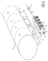
- a general reference tank 34 can be fitted with four compartments 35, 36, 37, 38 connected respectively to four assembled or "flanged" valves, by a pipe 39 attached to the end 30 and extending the conduit right 2 of each valve.
- the stack of valves thus constitutes a manifold with several channels and the equipment is of course completed by the usual members such as shut-off valves (bottom valves) 40 on each compartment and 41 on a general pipe, meter 42 and all other necessary organs, for example pump, by means of this arrangement, the following operations can thus be carried out in particular: source loading by dry coupler, compartment by compartment from 31 to 39; loading at source by dry coupler from 32 or 41 to 39, which makes it possible to load several compartments with a single coupling; unloading counted at 42 by passing from 39 to 41, which makes it possible to empty several compartments without handling a hose; gravity unloading from 39 to 33 by measuring compartment.
Landscapes
- Engineering & Computer Science (AREA)
- General Engineering & Computer Science (AREA)
- Mechanical Engineering (AREA)
- Health & Medical Sciences (AREA)
- Public Health (AREA)
- Transportation (AREA)
- Valve Housings (AREA)
- Multiple-Way Valves (AREA)
Claims (5)
- Modulares Ventil vom Typ mit einem quaderförmigen Gehäuse (1) mit Leitungen (2,5,8) und Klappenventilen (9,10) zum Herstellen und Unterbrechen von Verbindungen zwischen den Leitungen mit zwei ebenen parallelen Seiten (6,7) des quaderförmigen Gehäuses, welche die Bildung eines Stapels mit so vielen Ventilen wie gewünschten Wegen ermöglichen, mit einer geraden Leitung (2), welche das Gehäuse (1) von der einen zur anderen Seite zwischen zwei gegenüberliegenden ebenen Seiten (3,4) durchsetzt, dadurch gekennzeichnet, daß es eine T-Leitung aufweist, deren Stamm mit der geraden Leitung (2) in Verbindung steht und deren gerader Zweig (5) das Gehäuse von einer zur anderen Seite zwischen den parallelen ebenen Seiten (6,7) senkrecht zu den zwei ebenen gegenüberliegenden Seiten (3,4) durchsetzt, und eine gebogene Leitung (8) aufweist, von der ein erstes Ende in der geraden Leitung (2) mündet und das zweite Ende (33) an der gleichen Seite (4) wie ein Ende (31) der geraden Leitung (2) und parallel zu dieser mündet, wobei die T-Leitung und die gebogene Leitung (8) in der geraden Leitung (2) mittels Klappenventilen (9,10) mit pneumatischer Einzelbetätigung (21,22) münden, welche mit elastischer Rückstellung beaufschlagt sind.
- Ventil nach Anspruch 1, dadurch gekennzeichnet, daß jedes Klappenventil eine Stange (11) aufweist, deren der Klappe entgegengesetztes Ende mit zwei Platten (16,17) für die Abstützung einer Rückstellfeder (14) versehen ist, welche miteinander für die Befestigung einer elastischen Membran (18) sorgen, die in einem am Gehäuse (1) befestigten Gehäuse (20) montiert ist, das eine Innenkammer (21) begrenzt, die mit einem Anschluß (22) für eine pneumatische Druckmittelquelle verbunden ist.
- Ventil nach einem der Ansprüche 1 oder 2, dadurch gekennzeichnet, daß eine der zwei ebenen parallelen Flächen eine mit setzen einer Dichtung sowie Bohrungen (27) für den Durchtritt von Zugstangen (28) für die Bildung einer Stapelanordnung aufweist.
- Ventil nach einem der Ansprüche 1 bis 3, dadurch gekennzeichnet, daß jedes Ende (30,31,32,33) der jeweiligen Leitungen (2,5,8) mit einem Stutzen (Kuppelstück) versehen ist.
- Modulanordnung bestehend aus einem Stapel von modularen Ventilen nach einem der Ansprüche 1 bis 4, welche eine Sammelleitung mit mehreren Wegen für einen Mehrkammertank bildet.
Applications Claiming Priority (2)
| Application Number | Priority Date | Filing Date | Title |
|---|---|---|---|
| FR8814448A FR2643128B1 (fr) | 1988-11-04 | 1988-11-04 | Vanne a commande pneumatique |
| FR8814448 | 1988-11-04 |
Publications (2)
| Publication Number | Publication Date |
|---|---|
| EP0367100A1 EP0367100A1 (de) | 1990-05-09 |
| EP0367100B1 true EP0367100B1 (de) | 1993-12-29 |
Family
ID=9371598
Family Applications (1)
| Application Number | Title | Priority Date | Filing Date |
|---|---|---|---|
| EP19890119874 Expired - Lifetime EP0367100B1 (de) | 1988-11-04 | 1989-10-26 | Ventil mit pneumatischer Betätigung |
Country Status (3)
| Country | Link |
|---|---|
| EP (1) | EP0367100B1 (de) |
| DE (1) | DE68911857T2 (de) |
| FR (1) | FR2643128B1 (de) |
Families Citing this family (2)
| Publication number | Priority date | Publication date | Assignee | Title |
|---|---|---|---|---|
| US5305788A (en) * | 1992-08-13 | 1994-04-26 | Whitey Co. | Stream selector for process analyzer |
| CN107701788A (zh) * | 2017-08-15 | 2018-02-16 | 叶子建 | 一种可控性较强的蓄水池控制阀门 |
Family Cites Families (5)
| Publication number | Priority date | Publication date | Assignee | Title |
|---|---|---|---|---|
| US2557177A (en) * | 1946-08-30 | 1951-06-19 | Frees Joseph H De | Valve structure |
| US2792014A (en) * | 1953-02-24 | 1957-05-14 | Albert J Granberg | Tank filling and control system |
| US3134395A (en) * | 1960-02-18 | 1964-05-26 | Nat Tank Co | Manifold valve |
| US3360000A (en) * | 1966-04-15 | 1967-12-26 | Gloster Saro Ltd | Discharging arrangements for bulk fluids |
| FR2145858A5 (en) * | 1971-07-15 | 1973-02-23 | Merlin Andre | Pneumatics distribution panel - comprises easily-changed assembly of modular valve blocks |
-
1988
- 1988-11-04 FR FR8814448A patent/FR2643128B1/fr not_active Expired - Fee Related
-
1989
- 1989-10-26 EP EP19890119874 patent/EP0367100B1/de not_active Expired - Lifetime
- 1989-10-26 DE DE1989611857 patent/DE68911857T2/de not_active Expired - Fee Related
Also Published As
| Publication number | Publication date |
|---|---|
| EP0367100A1 (de) | 1990-05-09 |
| FR2643128B1 (fr) | 1991-05-31 |
| DE68911857D1 (de) | 1994-02-10 |
| DE68911857T2 (de) | 1994-07-14 |
| FR2643128A1 (fr) | 1990-08-17 |
Similar Documents
| Publication | Publication Date | Title |
|---|---|---|
| EP0922902B1 (de) | Kupplungsstück zwischen einem Druckgassetzgerät und einer Druckgaspatrone | |
| JP3822237B2 (ja) | 圧力トランスミッタ用マニホールド | |
| EP0692312B1 (de) | Doppelspender für flüssige Medien | |
| EP3567348A1 (de) | Verbesserter fluidtank | |
| EP1148953A1 (de) | Spender für chemisch instabile produkte | |
| EP0903255B1 (de) | Pumpvorrichtung und Kraftfahrzeug mit einer solchen Vorrichtung | |
| EP0367100B1 (de) | Ventil mit pneumatischer Betätigung | |
| EP3738841B1 (de) | Verteilungssystem eines fluids für fahrzeug, entsprechender fluidverteiler und fluidausstossverfahren, das ein solches system verwendet | |
| FR3096011A1 (fr) | distributeur fluidique pour un système de distribution de fluide pour véhicule et procédé d’éjection d’un fluide utilisant un tel système | |
| JP4262833B2 (ja) | 保護ケース入り袋の弁装置 | |
| WO2006030110A1 (fr) | Couvercle pour systeme de pulverisation multi-reservoir dote d’un organe de pressurisation type valve de pneu de vehicule | |
| FR2563889A1 (fr) | Distributeur de liquide et appareillage de serrage utilisant ce distributeur | |
| EP0013579A2 (de) | Kopfstück für Flüssiggasbehälter | |
| EP3811387B1 (de) | Elektromagnetische vorrichtung mit einem in einem zwischengehäuse angeordneten dampfauslasskanal | |
| FR2459188A1 (fr) | Dispositif d'aeration par decharge brusque d'air comprime | |
| FR2962986A1 (fr) | Dispositif pour distribuer un liquide, et procede de fabrication d'un tel dispositif. | |
| CA2378167C (en) | Switchover valve for gas supply system | |
| JPH0112063Y2 (de) | ||
| EP0588164B1 (de) | Verbindungsvorrichtung für eine in einer Dampfbügeleinrichtung montierte Entmineralisierungshülse | |
| FR2492278A1 (fr) | Dispositif de revetement | |
| EP0324698A1 (de) | Ventil zum Überleiten von pulverförmigen oder flüssigen Produkten unter geregeltem Luftdruck | |
| US7219693B2 (en) | Container shut-off valve with venting | |
| EP0607770A1 (de) | Doppelarmatur Anordnung | |
| EP0385816B1 (de) | Druckfluidspeicher | |
| JPH0350160B2 (de) |
Legal Events
| Date | Code | Title | Description |
|---|---|---|---|
| PUAI | Public reference made under article 153(3) epc to a published international application that has entered the european phase |
Free format text: ORIGINAL CODE: 0009012 |
|
| AK | Designated contracting states |
Kind code of ref document: A1 Designated state(s): BE CH DE ES GB IT LI LU NL SE |
|
| 17P | Request for examination filed |
Effective date: 19901026 |
|
| 17Q | First examination report despatched |
Effective date: 19920723 |
|
| GRAA | (expected) grant |
Free format text: ORIGINAL CODE: 0009210 |
|
| AK | Designated contracting states |
Kind code of ref document: B1 Designated state(s): BE CH DE ES GB IT LI LU NL SE |
|
| PG25 | Lapsed in a contracting state [announced via postgrant information from national office to epo] |
Ref country code: IT Free format text: LAPSE BECAUSE OF FAILURE TO SUBMIT A TRANSLATION OF THE DESCRIPTION OR TO PAY THE FEE WITHIN THE PRE;WARNING: LAPSES OF ITALIAN PATENTS WITH EFFECTIVE DATE BEFORE 2007 MAY HAVE OCCURRED AT ANY TIME BEFORE 2007. THE CORRECT EFFECTIVE DATE MAY BE DIFFERENT FROM THE ONE RECORDED.SCRIBED TIME-LIMIT Effective date: 19931229 Ref country code: ES Free format text: THE PATENT HAS BEEN ANNULLED BY A DECISION OF A NATIONAL AUTHORITY Effective date: 19931229 Ref country code: NL Effective date: 19931229 Ref country code: SE Effective date: 19931229 |
|
| REF | Corresponds to: |
Ref document number: 68911857 Country of ref document: DE Date of ref document: 19940210 |
|
| GBT | Gb: translation of ep patent filed (gb section 77(6)(a)/1977) |
Effective date: 19940427 |
|
| NLV1 | Nl: lapsed or annulled due to failure to fulfill the requirements of art. 29p and 29m of the patents act | ||
| PG25 | Lapsed in a contracting state [announced via postgrant information from national office to epo] |
Ref country code: LI Effective date: 19941031 Ref country code: CH Effective date: 19941031 Ref country code: LU Free format text: LAPSE BECAUSE OF NON-PAYMENT OF DUE FEES Effective date: 19941031 |
|
| PLBE | No opposition filed within time limit |
Free format text: ORIGINAL CODE: 0009261 |
|
| STAA | Information on the status of an ep patent application or granted ep patent |
Free format text: STATUS: NO OPPOSITION FILED WITHIN TIME LIMIT |
|
| 26N | No opposition filed | ||
| REG | Reference to a national code |
Ref country code: CH Ref legal event code: PL |
|
| PGFP | Annual fee paid to national office [announced via postgrant information from national office to epo] |
Ref country code: GB Payment date: 19961025 Year of fee payment: 8 |
|
| PGFP | Annual fee paid to national office [announced via postgrant information from national office to epo] |
Ref country code: DE Payment date: 19961028 Year of fee payment: 8 |
|
| PGFP | Annual fee paid to national office [announced via postgrant information from national office to epo] |
Ref country code: BE Payment date: 19961031 Year of fee payment: 8 |
|
| PG25 | Lapsed in a contracting state [announced via postgrant information from national office to epo] |
Ref country code: GB Free format text: LAPSE BECAUSE OF NON-PAYMENT OF DUE FEES Effective date: 19971026 |
|
| PG25 | Lapsed in a contracting state [announced via postgrant information from national office to epo] |
Ref country code: BE Free format text: LAPSE BECAUSE OF NON-PAYMENT OF DUE FEES Effective date: 19971031 |
|
| BERE | Be: lapsed |
Owner name: MOUVEX Effective date: 19971031 |
|
| GBPC | Gb: european patent ceased through non-payment of renewal fee |
Effective date: 19971026 |
|
| PG25 | Lapsed in a contracting state [announced via postgrant information from national office to epo] |
Ref country code: DE Free format text: LAPSE BECAUSE OF NON-PAYMENT OF DUE FEES Effective date: 19980701 |