EP0366942B1 - Ski brake - Google Patents
Ski brake Download PDFInfo
- Publication number
- EP0366942B1 EP0366942B1 EP89118128A EP89118128A EP0366942B1 EP 0366942 B1 EP0366942 B1 EP 0366942B1 EP 89118128 A EP89118128 A EP 89118128A EP 89118128 A EP89118128 A EP 89118128A EP 0366942 B1 EP0366942 B1 EP 0366942B1
- Authority
- EP
- European Patent Office
- Prior art keywords
- ski
- pedal
- arms
- brake
- arm
- Prior art date
- Legal status (The legal status is an assumption and is not a legal conclusion. Google has not performed a legal analysis and makes no representation as to the accuracy of the status listed.)
- Expired - Lifetime
Links
- 238000004519 manufacturing process Methods 0.000 abstract description 2
- 210000000629 knee joint Anatomy 0.000 description 4
- 210000002414 leg Anatomy 0.000 description 2
- 230000007704 transition Effects 0.000 description 2
- 230000000994 depressogenic effect Effects 0.000 description 1
Images

Classifications
-
- A—HUMAN NECESSITIES
- A63—SPORTS; GAMES; AMUSEMENTS
- A63C—SKATES; SKIS; ROLLER SKATES; DESIGN OR LAYOUT OF COURTS, RINKS OR THE LIKE
- A63C7/00—Devices preventing skis from slipping back; Ski-stoppers or ski-brakes
- A63C7/10—Hinged stoppage blades attachable to the skis in such manner that these blades can be moved out of the operative position
- A63C7/1006—Ski-stoppers
- A63C7/1013—Ski-stoppers actuated by the boot
- A63C7/1033—Ski-stoppers actuated by the boot articulated about at least two transverse axes
- A63C7/104—Ski-stoppers actuated by the boot articulated about at least two transverse axes laterally retractable above the ski surface
Definitions
- the present invention relates to ski brakes according to the preamble of claims 1 and 2, respectively.
- the aforementioned have an essential advantage, which is that the pedal practically only performs a pivoting movement when the knee joint is passed, i.e. moves in the longitudinal direction of the surface of the ski. This keeps frictional resistance, especially between the pedal and the ski boot, very low.
- the purpose of the present invention is to further develop and design the generic ski brakes in such a way that, while maintaining their specific advantages, a simplification of the pedal can be achieved, which on the one hand allows cheaper production and on the other hand increases the functional reliability of the ski brake.
- a surface in the pedal can be used as the actuating element that extends at least approximately at right angles to the tread surface and parallel to the articulation axis of the pedal.
- the free ends of the bends Holding arms are extended cam-like on their side facing the pivot axis of the brake.
- a second embodiment of the invention provides a slide as an actuating element, which is mounted in the pedal at least approximately parallel to its tread surface and can be influenced by the second arm of the toggle lever.
- the free ends of the bends of the holding arms are expediently acted upon by an expansion spring.
- a leaf spring supported on both ends in the pedal is provided as the spreading spring.
- the ski brake shown in FIGS. 1 to 3 has a base plate 1 with which it is screwed onto a ski 2, for example.
- the base plate can be correspondingly extended in a manner known per se and can carry a binding part of a safety ski binding.
- the base plate is expediently not connected to the ski directly but via a guide plate, on which it is held so as to be displaceable in the longitudinal direction of the ski.
- the ski brake comprises two brake brackets 3, 4 arranged on both sides of the ski 2 (see in particular FIG. 3), which are formed from round wire pieces and are essentially Z-shaped.
- the webs 5 are mounted on the base plate 1 and form swivel axis parts which run approximately at right angles to the longitudinal axis of the ski and approximately coaxially with one another.
- the left leg 6 in relation to the illustrations form the holding arms, while the right leg 7 form the brake arms.
- the free ends of the holding arms 6 are angled toward one another and form bearing journals 8 for a pedal 9 which can be actuated by a ski boot, not shown.
- This pedal forms an arm of a toggle lever, the second arm 10 of which is mounted on the base plate 1 at a distance from the swivel axis parts by means of a bearing pin 11.
- the knee joint is formed by an axle pin 12 which is pivotally and displaceably mounted in the pedal, for which purpose it engages with its free ends in guide grooves 13 of the pedal.
- the toggle lever arm 10 is under the influence of a spring, not shown, which loads it clockwise in relation to the representations and thus the ski brake in to keep their braking position.
- this spring can be designed as a spiral spiral spring and can be mounted on the journal 11.
- the angled portions of the holding arms 6 serving as bearing pins 8 for the pedal 9 each have a cam-like extension 14 (see in particular FIG. 2). These serve to interact with an actuating element, which in the present case is formed by a surface 15 of a pressure piece 16 in the pedal 9, which extends at least approximately at right angles to the tread surface and parallel to the articulation axis of the pedal.
- the free ends of the bends 8 are acted upon by a leaf spring 17 supported at both ends in the pedal 9.
- the position of the ski brake according to FIG. 1 is a transition position which is achieved when the ski boot, not shown, is inserted into the safety ski binding, also not shown.
- the ski brake has been pivoted from its braking position counter to the spring force loading the toggle lever arm 10 in a counterclockwise direction with respect to the illustration.
- the brake brackets 3, 4 swivel in as shown in the lower half of FIG. 3. This swiveling takes place by the action of the surface 15 of the extension 14 of the bends 8 adjacent thrust piece 16. This pivoting takes place against the force of the leaf spring 17, so that this causes the brake bracket 3, 4 to spread when the brake is raised after the load on the pedal 9 has ceased.
- the basic structure of the ski brake according to FIGS. 4 to 6 corresponds to that of FIGS. 1 to 3.
- a base plate 21 is again provided, by means of which the ski brake is held on the ski 22.
- the two brake brackets are designated by 23 and 24 and each comprise a web 25, a holding arm 26 and a braking arm 27. Angles of the holding arms 26 in turn form bearing pins 28 for a pedal 29.
- the pedal 29 forms a toggle lever, the knee joint of which is formed by an axle journal 32 which engages with its free ends in guide grooves 33 of the pedal.
- the arm 30 is also under the influence of a spring.
- a slide 34 is provided here as the actuating element, which is mounted in the pedal 29 so as to be displaceable at least approximately parallel to its tread surface and can be influenced by the arm 30.
- the slide acts on the free ends of the angled loops 28, which in turn are acted upon by a leaf spring 37 supported at both ends in the pedal 29.
- the axle journal 32 is displaced in the guide grooves 33 of the pedal 29.
- the arm 30 presses with its inner end against the slide 34 and causes it to be displaced in the pedal.
- the slider acting on the free ends of the bends 28 thereby causes the brake brackets 23, 24 to pivot in as a Comparison of the two halves of Figure 6 reveals.
- the spreading of the brake bracket is in turn effected by the leaf spring 37 when the brake is raised after the load on the pedal 29 has ceased.
Abstract
Description
Die vorliegende Erfindung bezieht sich auf Skibremsen gemäß dem Oberbegriff der Patentansprüche 1 bzw. 2.The present invention relates to ski brakes according to the preamble of
Bei diesen vorbekannten Skibremsen, die in ihrem grundsätzlichen Aufbau in der FR-A-2 516 392 beschrieben sind, erfolgt das Einschwenken in die Bereitschaftstellung dadurch, daß beim Durchtreten des Kniegelenks, wenn die Bremsarme sich in skiparalleler Lage befinden, das Pedal mit auf der Unterseite vorgesehenen Rampen, die die Haltearme bildenden Teile der Rundradstücke so beeinflußt, daß diese zur Skilängsachse hin bewegt werden.In these known ski brakes, which are described in their basic structure in FR-A-2 516 392, the swiveling into the standby position takes place in that when the knee joint is passed, when the brake arms are in a parallel position with the ski, the pedal is on the Underside provided ramps, which influences the parts of the circular wheel pieces forming the holding arms so that they are moved towards the longitudinal axis of the ski.
Gegenüber weiter bekannten aber gattungsfremden Skibremsen weisen die vorerwähnten einen wesentlichen Vorteil auf, der darin besteht, daß das Pedal beim Durchtreten des Kniegelenks praktisch nur eine Schwenkbewegung ausführt, d.h. sich gegenüber der Oberfläche des Ski in dessen Längsrichtung bewegt. Hierdurch werden Reibungswiderstände insbesondere zwischen Pedal und Skischuh sehr gering gehalten.Compared to other well-known but non-generic ski brakes, the aforementioned have an essential advantage, which is that the pedal practically only performs a pivoting movement when the knee joint is passed, i.e. moves in the longitudinal direction of the surface of the ski. This keeps frictional resistance, especially between the pedal and the ski boot, very low.
Zweck der vorliegenden Erfindung ist es, die gattungsgemäßen Skibremsen konstruktiv so weiterzubilden und zu gestalten, daß unter Beibehaltung ihrer spezifischen Vorteile sich eine Vereinfachung des Pedals erreichen läßt, die einerseits eine billigere Herstellung gestattet und andererseits die Funktionssicherheit der Skibremse erhöht.The purpose of the present invention is to further develop and design the generic ski brakes in such a way that, while maintaining their specific advantages, a simplification of the pedal can be achieved, which on the one hand allows cheaper production and on the other hand increases the functional reliability of the ski brake.
Erfindungsgemäß ist dies durch die kennzeichnenden Merkmale des Patentanspruchs 1 bzw. 2 erreicht. Dabei kann bei der ersten Ausführungsform als Betätigungselement eine Fläche im Pedal dienen, die sich wenigstens annähernd rechtwinkelig zur Trittfläche und parallel zur Anlenkachse des Pedals erstreckt. In konstruktiver Ausgestaltung dieses Erfindungsgedankens hat es sich als vorteilhaft erwiesen, daß die freien Enden der Abwinkelungen der Haltearme auf ihrer zur Schwenkachse der Bremse hin gerichteten Seite nockenartig erweitert sind.According to the invention, this is achieved by the characterizing features of
Dagegen sieht eine zweite Ausführungsform der Erfindung als Betätigungselement einen Schieber vor, der im Pedal wenigstens annähernd parallel zu dessen Trittfläche gelagert und von dem zweiten Arm des Kniehebels beeinflußbar ist.In contrast, a second embodiment of the invention provides a slide as an actuating element, which is mounted in the pedal at least approximately parallel to its tread surface and can be influenced by the second arm of the toggle lever.
Zweckmäßig sind die freien Enden der Abwinkelungen der Haltearme von einer Spreizfeder beaufschlagt. Vorzugsweise ist als Spreizfeder eine beidendig im Pedal abgestützte Blattfeder vorgesehen.The free ends of the bends of the holding arms are expediently acted upon by an expansion spring. Preferably, a leaf spring supported on both ends in the pedal is provided as the spreading spring.
Ausführungsbeispiel der Erfindung sind im folgenden anhand der Zeichnungen ausführlich beschrieben.
Es zeigen:
- Fig. 1
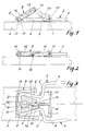
- einen zentralen vertikalen Längsschnitt durch eine erste Skibremse mit in skiparalleler Lage liegendem Bremsarm,
- Fig. 2
- die Skibremse im Schnitt entsprechend Fig. 1, jedoch in der Bereitschaftsstellung, und
- Fig. 3
- die Bremse in Draufsicht mit aufgeschnittenem Pedal, wobei die obere Hälfte den Momentanzustand entsprechend Fig. 1 und die untere Hälfte den Momentanzustand entsprechend Fig. 2 zeigt, und
- Fig. 4 bis 6
- den Fig. 1 bis 3 entsprechende Darstellungen eines zweiten Ausführungsbeispiels der Skibremse.
Show it:
- Fig. 1
- a central vertical longitudinal section through a first ski brake with a brake arm lying in a ski-parallel position,
- Fig. 2
- the ski brake in section corresponding to FIG. 1, but in the standby position, and
- Fig. 3
- the brake in plan view with the pedal cut open, the upper half showing the current status according to FIG. 1 and the lower half showing the current status according to FIG. 2, and
- 4 to 6
- 1 to 3 corresponding representations of a second embodiment of the ski brake.
Die in den Figuren 1 bis 3 dargestellte Skibremse besitzt eine Grundplatte 1, mit der sie beispielsweise auf einen Ski 2 geschraubt ist. Die Grundplatte kann in an sich bekannter Weise entsprechend verlängert sein und einen Bindungsteil einer Sicherheitsskibindung tragen. Insbesondere in diesem Fall ist die Grundplatte zweckmäßig nicht unmittelbar sondern über eine Führungsplatte mit dem Ski verbunden, an der sie in Skilängsrichtung verschiebbar gehalten ist.The ski brake shown in FIGS. 1 to 3 has a
Die Skibremse umfaßt zwei beidseitig des Ski 2 angeordnete Bremsbügel 3,4 (siehe insbesondere Fig. 3), die aus Runddrahtstücken gebildet und im wesentlichen Z-förmig gestaltet sind. Die Stege 5 sind auf der Grundplatte 1 gelagert und bilden Schwenkachsenteile, die etwa rechtwinkelig zur Längsachse des Ski und etwa koaxial zueinander verlaufen. Die in Bezug auf die Darstellungen linken Schenkel 6 bilden die Haltearme, während die rechten Schenkel 7 die Bremsarme bilden.The ski brake comprises two
Die freien Enden der Haltearme 6 sind aufeinander zu abgewinkelt und bilden Lagerzapfen 8 für ein Pedal 9, das von einem nicht dargestellten Skischuh zu betätigen ist. Dieses Pedal bildet einen Arm eines Kniehebels, dessen zweiter Arm 10 mit Abstand von den Schwenkachsenteilen mittels eines Lagerzapfens 11 an der Grundplatte 1 gelagert ist. Das Kniegelenk ist durch einen Achszapfen 12 gebildet, der im Pedal schwenkbar und verschiebbar gelagert ist, wozu er mit seinen freien Enden in Führungsnuten 13 des Pedals eingreift.The free ends of the
Der Kniehebelarm 10 steht unter dem Einfluß einer nicht dargestellten Feder, die ihn in Bezug auf die Darstellungen im Uhrzeigersinn belastet und damit die Skibremse in ihrer Bremsstellung zu halten trachtet. In bekannter Weise kann diese Feder als gewundene Biegefeder ausgebildet und auf dem Lagerzapfen 11 gelagert sein.The
Die als Lagerzapfen 8 für das Pedal 9 dienenden Abwinkelungen der Haltearme 6 weisen jeweils eine nockenartige Erweiterung 14 auf (siehe insbesonder Fig. 2). Diese dienen zum Zusammenwirken mit einem Betätigungselement, das im vorliegenden Fall von einer Fläche 15 eines Druckstücks 16 im Pedal 9 gebildet ist, die sich wenigstens annähernd rechtwinkelig zur Trittfläche und parallel zur Anlenkachse des Pedals erstreckt. Die freien Enden der Abwinkelungen 8 sind von einer beidendig im Pedal 9 abgestützten Blattfeder 17 beaufschlagt.The angled portions of the
Die Position der Skibremse nach Figur 1 ist eine Übergangsposition, die beim Einsetzen des nicht dargestellten Skischuhs in die ebenfalls nicht dargestellte Sicherheits-Skibindung erreicht wird. Die Skibremse ist aus ihrer Bremsstellung entgegen der den Kniehebelarm 10 belastenden Federkraft in Bezug auf die Darstellung entgegen dem Uhrzeigersinn geschwenkt worden. Beim weiteren Niedertreten des Pedals in die in Figur 2 gezeigte Position, der Bereitschaftsstellung, erfolgt das Einschwenken der Bremsbügel 3,4 entsprechend der Darstellung in der unteren Hälfte der Figur 3. Dieses Einschwenken geschieht durch Einwirkung des mit der Fläche 15 der Erweiterung 14 der Abwinkelungen 8 anliegenden Druckstücks 16. Dieses Einschwenken erfolgt entgegen der Kraft der Blattfeder 17, so daß diese ein Spreizen der Bremsbügel 3,4 bewirkt, wenn sich die Bremse nach Fortfall der Belastung des Pedals 9 aufstellt.The position of the ski brake according to FIG. 1 is a transition position which is achieved when the ski boot, not shown, is inserted into the safety ski binding, also not shown. The ski brake has been pivoted from its braking position counter to the spring force loading the
Die Skibremse nach den Figuren 4 bis 6 entspricht in ihrem grundsätzlichen Aufbau der Ausführung nach den Figuren 1 bis 3. So ist wiederum eine Grundplatte 21 vorhanden, über die die Skibremse auf dem Ski 22 gehalten ist. Die beiden Bremsbügel sind mit 23 und 24 bezeichnet und umfassen jeweils einen Steg 25, einen Haltearm 26 und einen Bremsarm 27. Abwinkelungen der Haltearme 26 bilden wiederum Lagerzapfen 28 für ein Pedal 29.The basic structure of the ski brake according to FIGS. 4 to 6 corresponds to that of FIGS. 1 to 3. Thus, a
Zusammen mit einem Arm 30 bildet das Pedal 29 einen Kniehebel, dessen Kniegelenk durch einen Achszapfen 32 gebildet ist,der mit seinen freien Enden in Führungsnuten 33 des Pedals eingreift. Wie bei der ersten Ausführung steht auch hier der Arm 30 unter dem Einfluß einer Aufstellfeder.Together with an
Im Gegensatz zur ersten Ausführung ist hier als Betätigungselement ein Schieber 34 vorgesehen, der im Pedal 29 wenigstens annähernd parallel zu dessen Trittfläche verschiebbar gelagert und von dem Arm 30 beeinflußbar ist. Der Schieber wirkt auf die freien Enden der Abwinkslungen 28, die andererseits wiederum von einer beidendig im Pedal 29 abgestützten Blattfeder 37 beaufschlagt werden.In contrast to the first embodiment, a
Beim Übergang aus der Zwischenposition nach Figur 4 in die Bereitschaftsstellung nach Figur 5 erfolgt eine Verschiebung des Achszapfens 32 in den Führungsnuten 33 des Pedals 29. Hierbei drückt der Arm 30 mit seinem inneren Ende gegen den Schieber 34 und bewirkt dessen Verschiebung im Pedal. Der an den freien Enden der Abwinkelungen 28 angreifende Schieber bewirkt dadurch das Einschwenken der Bremsbügel 23, 24, wie ein Vergleich der beiden Hälften der Figur 6 erkennen läßt. Das Spreizen der Bremsbügel wird wiederum durch die Blattfeder 37 bewirkt, wenn sich die Bremse nach Fortfall der Belastung des Pedals 29 aufstellt.During the transition from the intermediate position according to FIG. 4 to the ready position according to FIG. 5, the
Claims (5)
- Ski brake with two brake arms (3, 4) arranged on each side of the ski (2), each of said arms (3, 4) being formed with an integral pivot axis section (5) and a retaining arm (6) from an essentially Z-shaped round-section rod, with the pivot axis sections (5) running approximately at right angles to the longitudinal axis of the ski (2) and approximately coaxially to each other, and being mounted on the top of the ski (2) by means of a retaining plate (1), and with the free ends (8) of the retaining arms being angled towards each other and serving as the bearings for a pedal (9) which can be operated by the ski boot, said pedal (9) forming an arm of a toggle lever, of which the second arm (10) is securely mounted on the ski at a distance from the pivot axis sections, and of which the toggle joint is formed by a pivot-and-shift bearing, with the brake arms (3, 4) being pivotable against a spring force out of the braking position into a ski-parallel position and being pivotable in relation to the retaining arm ends towards the longitudinal axis of the ski (2) in a ready position, and with this pivoting action being performed by a relative movement of the pedal (9) in respect of the retaining arms (10),
characterised in that,
in the pedal (9) a surface (15) which is at least approximately perpendicular to the standing surface and parallel to the pivot axis (8) of the pedal (9), interacts as an actuating element with the angled sections (8) of the retaining arms (6) with the effect of pivoting the braking arms into position when the toggle joint (12) is moved towards the ski surface. - Ski brake with two brake arms (23, 24) arranged on each side of the ski (22), each of said arms (23, 24) being formed with an integral pivot axis section (25) and a retaining arm (26) from an essentially Z-shaped round-section rod, with the pivot axis sections (25) running approximately at right angles to the longitudinal axis of the ski (22) and approximately coaxially to each other, and being mounted on the top of the ski (22) by means of a retaining plate (21), and with the free ends (28) of the retaining arms being angled towards each other and serving as the bearings for a pedal (29) which can be operated by the ski boot, said pedal (29) forming an arm of a toggle lever, of which the second arm (30) is securely mounted on the ski at a distance from the pivot axis sections, and of which the toggle joint is formed by a pivot-and-shift bearing, with the brake arms (23, 24) being pivotable against a spring force out of the braking position into a ski-parallel position and being pivotable in relation to the retaining arm ends towards the longitudinal axis of the ski (22) in a ready position, and with this pivoting action being performed by a relative movement of the pedal (29) in respect of the retaining arms (30),
characterised in that
the pedal (29) exhibits a sliding element (34) which is mounted in the pedal (29) such that it is at least approximately parallel to its stepping face and can be influenced by the second arm (30) of the toggle lever, as an actuating element (34) which acts on the angled sections (28) with the effect of pivoting the braking arms into position when the toggle joint (32) is moved towards the ski surface. - Ski brake according to Claim 1 or 2, characterised in that the free ends of the angled sections (8) of the retaining arms (6) are expanded in a cam-like fashion (at 14) at the sides facing the pivot axis (5) of the brake.
- Ski brake according to one of the preceding claims, characterised in that the free ends of the angled sections (8, 28) of the retaining arms (6, 26) are pressurised by a split spring (17, 37).
- Ski brake according to Claim 4, characterised in that a leaf spring (17; 37) which is braced at both ends in the pedal (9; 29) is provided as the split spring.
Priority Applications (1)
| Application Number | Priority Date | Filing Date | Title |
|---|---|---|---|
| AT89118128T ATE97826T1 (en) | 1988-11-03 | 1989-09-29 | SKI BRAKE. |
Applications Claiming Priority (2)
| Application Number | Priority Date | Filing Date | Title |
|---|---|---|---|
| DE3837379 | 1988-11-03 | ||
| DE3837379A DE3837379C2 (en) | 1988-11-03 | 1988-11-03 | Ski brake |
Publications (3)
| Publication Number | Publication Date |
|---|---|
| EP0366942A2 EP0366942A2 (en) | 1990-05-09 |
| EP0366942A3 EP0366942A3 (en) | 1990-12-12 |
| EP0366942B1 true EP0366942B1 (en) | 1993-12-01 |
Family
ID=6366442
Family Applications (1)
| Application Number | Title | Priority Date | Filing Date |
|---|---|---|---|
| EP89118128A Expired - Lifetime EP0366942B1 (en) | 1988-11-03 | 1989-09-29 | Ski brake |
Country Status (6)
| Country | Link |
|---|---|
| US (1) | US5033766A (en) |
| EP (1) | EP0366942B1 (en) |
| JP (1) | JPH02177981A (en) |
| AT (1) | ATE97826T1 (en) |
| CZ (1) | CZ277994B6 (en) |
| DE (1) | DE3837379C2 (en) |
Families Citing this family (10)
| Publication number | Priority date | Publication date | Assignee | Title |
|---|---|---|---|---|
| US5158317A (en) * | 1988-11-03 | 1992-10-27 | Marker Deutschland Gmbh | Ski brake assembly |
| DE3918113C2 (en) * | 1989-06-02 | 1997-04-30 | Hans Meyer | Ski brake for a ski with a spring board supported resiliently against the ski |
| US5642897A (en) * | 1992-02-18 | 1997-07-01 | Salomon S.A. | Ski brake and device for modifying the natural pressure distribution of a ski over its sliding surface and a ski equipped therewith |
| FR2687325B1 (en) * | 1992-02-18 | 1995-10-27 | Salomon Sa | DEVICE FOR MODIFYING THE NATURAL DISTRIBUTION OF A SKI ON ITS SLIDING SURFACE, AND SKI EQUIPPED WITH SUCH A DEVICE. |
| DE9212157U1 (en) * | 1992-09-09 | 1994-01-13 | Marker Deutschland Gmbh | Pedal for ski brakes |
| AT409934B (en) * | 1994-01-28 | 2002-12-27 | Varpat Patentverwertung | BRAKE DEVICE FOR A SKI |
| DE19850297A1 (en) * | 1998-10-30 | 2000-05-04 | Marker Deutschland Gmbh | Ski brake has double arm swivel brake lever connected to control part by slide guide having detent recess to hold brake lever firm in braking position against large forces acting on lever |
| FR2788991B1 (en) * | 1999-02-02 | 2001-04-06 | Look Fixations Sa | SKI BRAKE |
| FR3040308B1 (en) * | 2015-08-27 | 2017-08-11 | Salomon Sas | BRAKING DEVICE FOR FIXING A SLIDING BOARD |
| DE102019108350A1 (en) * | 2019-03-29 | 2020-10-01 | Marker Deutschland Gmbh | Braking device |
Family Cites Families (21)
| Publication number | Priority date | Publication date | Assignee | Title |
|---|---|---|---|---|
| JPS53127039A (en) * | 1977-04-11 | 1978-11-06 | Hope Kk | Ski antiskid |
| AT366920B (en) * | 1977-04-27 | 1982-05-25 | Tyrolia Freizeitgeraete | SKI BRAKE |
| FR2453606A1 (en) * | 1978-07-04 | 1980-11-07 | Salomon & Fils F | PIVOT SKI FIXING ASSEMBLY HAVING A BRAKING SYSTEM |
| US4379570A (en) * | 1979-05-23 | 1983-04-12 | Marker-Patentverwertungsgesellschaft Mbh. | Ski stopper |
| FR2487685A1 (en) * | 1980-08-04 | 1982-02-05 | Look Sa | SKI BRAKE |
| DE3106688A1 (en) * | 1981-02-23 | 1982-09-09 | Hannes Marker Sicherheits-Skibindungen GmbH & Co KG, 8100 Garmisch-Partenkirchen | Ski brake |
| DE3107035A1 (en) * | 1981-02-25 | 1982-09-09 | Hannes Marker Sicherheits-Skibindungen GmbH & Co KG, 8100 Garmisch-Partenkirchen | HEEL TIGHTS FOR SAFETY SKI BINDINGS |
| AT374690B (en) * | 1981-03-13 | 1984-05-25 | Tyrolia Freizeitgeraete | SKI BRAKE |
| DE3110743A1 (en) * | 1981-03-19 | 1982-10-07 | Hannes Marker Sicherheits-Skibindungen GmbH & Co KG, 8100 Garmisch-Partenkirchen | SKISTOPPER |
| AT376891B (en) * | 1981-04-01 | 1985-01-10 | Tyrolia Freizeitgeraete | SKI BRAKE |
| DE3130677A1 (en) * | 1981-08-03 | 1983-02-17 | Geze Gmbh, 7250 Leonberg | Ski brake |
| DE3131917C2 (en) * | 1981-08-12 | 1995-07-13 | Marker Int | Heel tensioner for a ski binding with integrated ski brake |
| DE3136079A1 (en) * | 1981-09-11 | 1983-03-24 | Roland 8100 Garmisch-Partenkirchen Jungkind | Ski brake |
| DE3140819A1 (en) * | 1981-10-13 | 1983-04-21 | ess GmbH Skibindungen, 8978 Burgberg | SKI BRAKE |
| DE3145646A1 (en) * | 1981-11-17 | 1983-05-26 | Marker Patentverwertungsgesellschaft mbH, 6340 Baar | SKISTOPPER |
| US4470614A (en) * | 1982-04-14 | 1984-09-11 | Marker-Patentverwertungsgesellschaft Mbh | Ski brake |
| US4515388A (en) * | 1982-08-11 | 1985-05-07 | Marker International | Ski brake |
| FR2586578B1 (en) * | 1985-08-27 | 1987-12-24 | Salomon Sa | SKI BRAKE |
| FR2593074B1 (en) * | 1986-01-21 | 1989-09-15 | Salomon Sa | SKI BRAKE. |
| AT384554B (en) * | 1986-06-03 | 1987-12-10 | Tyrolia Freizeitgeraete | SKI BRAKE |
| DE3621944C2 (en) * | 1986-06-30 | 1996-08-08 | Marker Deutschland Gmbh | Integrated ski brake |
-
1988
- 1988-11-03 DE DE3837379A patent/DE3837379C2/en not_active Expired - Fee Related
-
1989
- 1989-09-29 EP EP89118128A patent/EP0366942B1/en not_active Expired - Lifetime
- 1989-09-29 AT AT89118128T patent/ATE97826T1/en not_active IP Right Cessation
- 1989-11-01 JP JP1286000A patent/JPH02177981A/en active Pending
- 1989-11-01 CZ CS896189A patent/CZ277994B6/en unknown
- 1989-11-02 US US07/431,045 patent/US5033766A/en not_active Expired - Fee Related
Also Published As
| Publication number | Publication date |
|---|---|
| EP0366942A3 (en) | 1990-12-12 |
| CZ277994B6 (en) | 1993-07-14 |
| DE3837379A1 (en) | 1990-05-10 |
| JPH02177981A (en) | 1990-07-11 |
| EP0366942A2 (en) | 1990-05-09 |
| DE3837379C2 (en) | 1997-10-23 |
| US5033766A (en) | 1991-07-23 |
| CZ618989A3 (en) | 1993-03-17 |
| ATE97826T1 (en) | 1993-12-15 |
Similar Documents
| Publication | Publication Date | Title |
|---|---|---|
| EP0366942B1 (en) | Ski brake | |
| DE3010409A1 (en) | TRANSFORMER DEVICE FOR A CLUTCH PEDAL | |
| DE2628205A1 (en) | DRUM BRAKE WITH AUTOMATIC ADJUSTMENT DEVICE | |
| EP1659017B1 (en) | Apparatus for reduction of the pedal force | |
| WO1982002495A1 (en) | Safety ski binding | |
| CH642553A5 (en) | SKI BRAKE. | |
| DE3140819C2 (en) | ||
| EP0316311B1 (en) | Ski brake | |
| WO1987007515A1 (en) | Ski brake | |
| DE3228803A1 (en) | SKI BRAKE | |
| AT389644B (en) | SKI BRAKE INTEGRATED WITH A HEEL TENSIONER FOR SAFETY SKI BINDINGS | |
| DE2758658A1 (en) | SKI BRAKE | |
| DE7915980U1 (en) | BRAKE ACTUATOR LEVER FOR A SELF-CENTERING PART COVER DISC BRAKE | |
| DE102005050760A1 (en) | Pedal force reduction device for motor vehicle, has piston rod indirectly connected to pedal in form-fitting manner | |
| EP0979741A2 (en) | Castor with brake for apparatus, devices, furniture and similar | |
| DE3106688C2 (en) | ||
| CH644275A5 (en) | SKI BRAKE. | |
| AT389819B (en) | Ski brake | |
| DE60100718T2 (en) | Device for attaching a ski boot to a ski | |
| DE10030275B4 (en) | Latching mechanism for a direction switch of a motor vehicle | |
| DE1920593U (en) | DISC BRAKE, IN PARTICULAR FOR HYDRAULIC BRAKE SYSTEMS. | |
| DE3134794C2 (en) | ||
| EP0044523B1 (en) | Fail-safe brake linkage for a vehicle with a hydraulic or pneumatic brake system | |
| DE2849621C3 (en) | Ski brake | |
| DE3526145C2 (en) | Integrated ski brake |
Legal Events
| Date | Code | Title | Description |
|---|---|---|---|
| PUAI | Public reference made under article 153(3) epc to a published international application that has entered the european phase |
Free format text: ORIGINAL CODE: 0009012 |
|
| AK | Designated contracting states |
Kind code of ref document: A2 Designated state(s): AT CH FR IT LI |
|
| PUAL | Search report despatched |
Free format text: ORIGINAL CODE: 0009013 |
|
| AK | Designated contracting states |
Kind code of ref document: A3 Designated state(s): AT CH FR IT LI |
|
| 17P | Request for examination filed |
Effective date: 19910326 |
|
| 17Q | First examination report despatched |
Effective date: 19920518 |
|
| GRAA | (expected) grant |
Free format text: ORIGINAL CODE: 0009210 |
|
| AK | Designated contracting states |
Kind code of ref document: B1 Designated state(s): AT CH FR IT LI |
|
| PG25 | Lapsed in a contracting state [announced via postgrant information from national office to epo] |
Ref country code: IT Free format text: LAPSE BECAUSE OF FAILURE TO SUBMIT A TRANSLATION OF THE DESCRIPTION OR TO PAY THE FEE WITHIN THE PRE;WARNING: LAPSES OF ITALIAN PATENTS WITH EFFECTIVE DATE BEFORE 2007 MAY HAVE OCCURRED AT ANY TIME BEFORE 2007. THE CORRECT EFFECTIVE DATE MAY BE DIFFERENT FROM THE ONE RECORDED.SCRIBED TIME-LIMIT Effective date: 19931201 |
|
| REF | Corresponds to: |
Ref document number: 97826 Country of ref document: AT Date of ref document: 19931215 Kind code of ref document: T |
|
| ET | Fr: translation filed | ||
| PG25 | Lapsed in a contracting state [announced via postgrant information from national office to epo] |
Ref country code: LI Effective date: 19940930 Ref country code: CH Effective date: 19940930 |
|
| PLBE | No opposition filed within time limit |
Free format text: ORIGINAL CODE: 0009261 |
|
| STAA | Information on the status of an ep patent application or granted ep patent |
Free format text: STATUS: NO OPPOSITION FILED WITHIN TIME LIMIT |
|
| 26N | No opposition filed | ||
| REG | Reference to a national code |
Ref country code: CH Ref legal event code: PL |
|
| PGFP | Annual fee paid to national office [announced via postgrant information from national office to epo] |
Ref country code: AT Payment date: 19980902 Year of fee payment: 10 |
|
| PGFP | Annual fee paid to national office [announced via postgrant information from national office to epo] |
Ref country code: FR Payment date: 19980916 Year of fee payment: 10 |
|
| PG25 | Lapsed in a contracting state [announced via postgrant information from national office to epo] |
Ref country code: AT Free format text: LAPSE BECAUSE OF NON-PAYMENT OF DUE FEES Effective date: 19990929 |
|
| PG25 | Lapsed in a contracting state [announced via postgrant information from national office to epo] |
Ref country code: FR Free format text: LAPSE BECAUSE OF NON-PAYMENT OF DUE FEES Effective date: 20000531 |
|
| REG | Reference to a national code |
Ref country code: FR Ref legal event code: ST |