EP0366691B1 - Servo-direction a cremaillere, en particulier pour vehicules a moteur - Google Patents
Servo-direction a cremaillere, en particulier pour vehicules a moteur Download PDFInfo
- Publication number
- EP0366691B1 EP0366691B1 EP19880905777 EP88905777A EP0366691B1 EP 0366691 B1 EP0366691 B1 EP 0366691B1 EP 19880905777 EP19880905777 EP 19880905777 EP 88905777 A EP88905777 A EP 88905777A EP 0366691 B1 EP0366691 B1 EP 0366691B1
- Authority
- EP
- European Patent Office
- Prior art keywords
- threaded spindle
- toothed rack
- rack
- assisted steering
- steering
- Prior art date
- Legal status (The legal status is an assumption and is not a legal conclusion. Google has not performed a legal analysis and makes no representation as to the accuracy of the status listed.)
- Expired - Lifetime
Links
Images

Classifications
-
- B—PERFORMING OPERATIONS; TRANSPORTING
- B62—LAND VEHICLES FOR TRAVELLING OTHERWISE THAN ON RAILS
- B62D—MOTOR VEHICLES; TRAILERS
- B62D5/00—Power-assisted or power-driven steering
- B62D5/04—Power-assisted or power-driven steering electrical, e.g. using an electric servo-motor connected to, or forming part of, the steering gear
- B62D5/0442—Conversion of rotational into longitudinal movement
- B62D5/0454—Worm gears
-
- B—PERFORMING OPERATIONS; TRANSPORTING
- B62—LAND VEHICLES FOR TRAVELLING OTHERWISE THAN ON RAILS
- B62D—MOTOR VEHICLES; TRAILERS
- B62D5/00—Power-assisted or power-driven steering
- B62D5/04—Power-assisted or power-driven steering electrical, e.g. using an electric servo-motor connected to, or forming part of, the steering gear
- B62D5/0421—Electric motor acting on or near steering gear
- B62D5/0424—Electric motor acting on or near steering gear the axes of motor and final driven element of steering gear, e.g. rack, being parallel
- B62D5/0427—Electric motor acting on or near steering gear the axes of motor and final driven element of steering gear, e.g. rack, being parallel the axes being coaxial
-
- B—PERFORMING OPERATIONS; TRANSPORTING
- B62—LAND VEHICLES FOR TRAVELLING OTHERWISE THAN ON RAILS
- B62D—MOTOR VEHICLES; TRAILERS
- B62D5/00—Power-assisted or power-driven steering
- B62D5/04—Power-assisted or power-driven steering electrical, e.g. using an electric servo-motor connected to, or forming part of, the steering gear
- B62D5/043—Power-assisted or power-driven steering electrical, e.g. using an electric servo-motor connected to, or forming part of, the steering gear characterised by clutch means between driving element, e.g. motor, and driven element, e.g. steering column or steering gear
- B62D5/0433—Power-assisted or power-driven steering electrical, e.g. using an electric servo-motor connected to, or forming part of, the steering gear characterised by clutch means between driving element, e.g. motor, and driven element, e.g. steering column or steering gear the clutch being of on-off type
- B62D5/0436—Power-assisted or power-driven steering electrical, e.g. using an electric servo-motor connected to, or forming part of, the steering gear characterised by clutch means between driving element, e.g. motor, and driven element, e.g. steering column or steering gear the clutch being of on-off type the clutch being a controlled emergency clutch, e.g. for disconnecting at motor break-down
-
- B—PERFORMING OPERATIONS; TRANSPORTING
- B62—LAND VEHICLES FOR TRAVELLING OTHERWISE THAN ON RAILS
- B62D—MOTOR VEHICLES; TRAILERS
- B62D5/00—Power-assisted or power-driven steering
- B62D5/04—Power-assisted or power-driven steering electrical, e.g. using an electric servo-motor connected to, or forming part of, the steering gear
- B62D5/0442—Conversion of rotational into longitudinal movement
- B62D5/0445—Screw drives
- B62D5/0448—Ball nuts
Definitions
- the invention relates to a power assisted rack and pinion steering, in particular for motor vehicles, according to the preamble of claim 1.
- auxiliary power steering is the subject of the older, unpublished international patent application PCT / EP 86/00426.
- the manual steering is supported by an electric motor, which can be brought into drive connection via a separating element.
- a safety switching device opens the isolator if incorrect information occurs in an electrical control circuit or in a redundant safety circuit, which could lead to a malfunction in the steering.
- the invention has for its object to further develop such a power assisted steering system in such a way that incorrect steering control can be prevented easily and safely.
- the rotary motion of the electric motor is easily converted into a reciprocating motion of the rack.
- the ball screw thread of the threaded spindle can have a comparatively small diameter, so that despite the required transmission ratio, a sufficiently large pitch angle results in a good return efficiency.
- the axial displaceability of the threaded spindle can be used in a simple manner for torque measurement for the safety switching device.
- a bellows is advantageously arranged between the threaded spindle and the one coupling half.
- the bellows also serves to compensate for misalignments in the drive train from the electric motor to the rack.
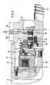
- the mechanical part of the power assisted rack and pinion steering contains a rack and pinion steering gear 1, the primary part of which is formed by a pinion 2 and the secondary part of which is formed by a rack 3.
- the pinion 2 is connected via a steering spindle connection 4 to a steering handwheel, not shown.
- the rack 3 is connected in a known manner via a steering linkage 5, 6 to the vehicle wheels to be steered.
- a torque measuring device 7 is installed between the steering spindle connection 4 and the pinion 2.
- the torque measuring device 7 detects the relative torque between the steering spindle connection 4 and the pinion 2 and controls the drive of an electric motor 8 via an electronic component (not shown).
- a ball nut 9 is rotatably connected.
- the ball nut 9 is in a driving connection via a ball race 10 with a threaded spindle 11.
- the threaded spindle 11 is connected to the electric motor 8 via a separating member in the form of a coupling 12, which is only shown schematically in FIG. 1.
- the pinion 2, the toothed rack 3, the ball nut 9, the clutch 12 and the intermediate parts are enclosed by a multi-part housing 13.
- a drive part 14 of the clutch 12 is rotatably connected to the output shaft 15 of the electric motor 8.
- An output part 16 of the clutch 12 is connected via a bellows 17 to a flange 18 fastened to the threaded spindle 11.
- the threaded spindle 11 is axially displaceably and rotatably supported by two elastic intermediate rings 19 and 20 and two axial bearings 21 and 22 relative to a housing base 23 of the fixed housing 13.
- a lever 24 which is axially displaceable together with the latter is arranged on the threaded spindle 11.
- the lever 24 is clamped between the one elastic intermediate ring 20 and the one axial bearing 22 and is thereby held against rotation with respect to the fixed housing 13.
- Two switches 25 and 26 are arranged on the housing 13 and can be actuated by the free end of the lever 24.
- the mist 24 is provided with an offset 27.
- a safety switching device 28 is formed by the two switches 25 and 26 and the lever 24.
- the function of the power assisted rack and pinion steering with the safety switching device is described in the following: If, for example, a turning moment of the steering handwheel, not shown, on the steering spindle connection 4 is initiated, this is supported by the pinion 2, the toothed rack 3 and the steering linkage 5, 6 on the vehicle wheels to be steered.
- the torque measuring device 7 registers a corresponding torque. This is processed in an electronic module, not shown, and the electric motor 8 is driven in the sense of a right-hand drive. This relieves the pinion 2 and axially displaces the threaded spindle 11.
- one of the axial bearings 21 and 22 is pressed against one of the elastic intermediate rings 19 and 20, respectively is compressed in accordance with the axial force exerted by the threaded spindle 11.
- the non-compressed elastic intermediate ring 20 or 19 expands in the process.
- the clamped end of the lever 24 moves together with the threaded spindle 11, so that the free end of the lever 24 is pressed in the opposite direction against one of the switches 25 or 26.
- the servo-electric support is not interrupted by the positive disconnection of the currentless switch 25 or 26.
- the desired reduction in the torque at the steering spindle connection 4 results from the servo-electric support. In this normal operating state, the clutch 12 is closed.
Abstract
Claims (5)
Applications Claiming Priority (2)
| Application Number | Priority Date | Filing Date | Title |
|---|---|---|---|
| DE3722058 | 1987-07-03 | ||
| DE3722058 | 1987-07-03 |
Publications (2)
| Publication Number | Publication Date |
|---|---|
| EP0366691A1 EP0366691A1 (fr) | 1990-05-09 |
| EP0366691B1 true EP0366691B1 (fr) | 1991-11-06 |
Family
ID=6330876
Family Applications (1)
| Application Number | Title | Priority Date | Filing Date |
|---|---|---|---|
| EP19880905777 Expired - Lifetime EP0366691B1 (fr) | 1987-07-03 | 1988-06-25 | Servo-direction a cremaillere, en particulier pour vehicules a moteur |
Country Status (5)
| Country | Link |
|---|---|
| US (1) | US5040631A (fr) |
| EP (1) | EP0366691B1 (fr) |
| JP (1) | JPH02504019A (fr) |
| DE (2) | DE3821501A1 (fr) |
| WO (1) | WO1989000124A1 (fr) |
Cited By (2)
| Publication number | Priority date | Publication date | Assignee | Title |
|---|---|---|---|---|
| DE4443781C1 (de) * | 1994-12-08 | 1996-04-25 | Steyr Daimler Puch Ag | Elektrische Servolenkung mit Sicherheitseinrichtung |
| WO2002099374A1 (fr) | 2001-06-01 | 2002-12-12 | Zf Lenksysteme Gmbh | Procede pour fixer un dispositif de mesure de couple de rotation |
Families Citing this family (12)
| Publication number | Priority date | Publication date | Assignee | Title |
|---|---|---|---|---|
| FR2689303B1 (fr) * | 1992-03-25 | 1997-08-14 | Volkswagen Ag | Dispositif commutateur. |
| DE4438930C1 (de) * | 1994-10-31 | 1995-10-26 | Daimler Benz Ag | Zahnstangenlenkung bzw. -steuerung mit Servomotor |
| US5924518A (en) * | 1996-07-24 | 1999-07-20 | Trw Inc. | Linear drive electric assist steering system |
| FR2797003B1 (fr) * | 1998-11-19 | 2001-11-30 | Valeo | Commande pour organe d'accouplement |
| FR2808759B1 (fr) * | 2000-05-10 | 2005-08-26 | Koyo Seiko Co | Appareil de direction assistee electrique |
| US6806595B2 (en) * | 2001-12-19 | 2004-10-19 | Applied Precision, Llc | Low backlash linear actuator |
| US7401677B2 (en) * | 2002-02-13 | 2008-07-22 | Trw Inc. | Self-centering steering system |
| DE10351366A1 (de) * | 2003-11-04 | 2005-06-09 | Zf Lenksysteme Gmbh | Aktuator |
| DE202004001740U1 (de) | 2004-02-05 | 2004-06-09 | Trw Automotive Gmbh | Zahnstangenlenkung, insbesondere für leichtere Lastkraftfahrzeuge |
| EP1574415B1 (fr) * | 2004-03-10 | 2007-01-10 | Umbra Cuscinetti S.p.A. | Unité de direction pour un véhicule électrique |
| ITTO20040168A1 (it) * | 2004-03-15 | 2004-06-15 | Skf Ab | Attuatore elettromeccanico lineare per un impianto sterzante di un veicolo a motore |
| DE102009045857A1 (de) * | 2009-10-20 | 2011-04-21 | Robert Bosch Gmbh | Verfahren zur Herstellung einer Spindel für einen Spindeltrieb, Wälzgewindetrieb mit einer solchen Spindel und Verwendung des Wälzgewindetriebs |
Family Cites Families (13)
| Publication number | Priority date | Publication date | Assignee | Title |
|---|---|---|---|---|
| US2313473A (en) * | 1941-08-23 | 1943-03-09 | Heacock Woodrow Arthur | Game device |
| GB667737A (en) * | 1950-04-04 | 1952-03-05 | Howard Nelson Moore | A new or improved apparatus for a game |
| US3464701A (en) * | 1966-12-06 | 1969-09-02 | Sch Corp | Game apparatus for playing threedimensional chess and tic-tac-toe |
| US3684285A (en) * | 1970-06-19 | 1972-08-15 | John Robert Kane | Chess game apparatus |
| GB1283840A (en) * | 1970-07-21 | 1972-08-02 | Kenneth John Clarke | Apparatus for three-dimensional chess game |
| US3879040A (en) * | 1973-10-29 | 1975-04-22 | W Ronald Smith | Three-dimensional tic-tac-toe game apparatus |
| US3884474A (en) * | 1974-08-22 | 1975-05-20 | James W Harper | Multi-tiered game board for three-dimensional tic-tac-toe games |
| US3888487A (en) * | 1974-11-05 | 1975-06-10 | Daniel C Replogle | Three dimensional tic-tac-toe device |
| FR2442476A1 (fr) * | 1978-11-21 | 1980-06-20 | Citroen Sa | Dispositif de commande en rotation d'un organe tournant recepteur |
| FR2492558A1 (fr) * | 1980-10-20 | 1982-04-23 | Citroen Sa | Mecanisme d'assistance rotative, notamment pour direction de vehicule |
| BR8707748A (pt) * | 1986-07-19 | 1989-08-15 | Zahnradfabrik Friedrichshafen | Direcao de forca auxiliar,especialmente para veiculos automotores |
| US5083626A (en) * | 1986-10-20 | 1992-01-28 | Honda Giken Kogyo Kabushiki Kaishi | Rear wheel steering device for vehicle with four steerable wheels |
| US4811813A (en) * | 1987-02-17 | 1989-03-14 | Trw Inc. | Center take-off electric rack and pinion steering gear |
-
1988
- 1988-06-25 US US07/445,722 patent/US5040631A/en not_active Expired - Fee Related
- 1988-06-25 JP JP63505435A patent/JPH02504019A/ja active Pending
- 1988-06-25 EP EP19880905777 patent/EP0366691B1/fr not_active Expired - Lifetime
- 1988-06-25 DE DE3821501A patent/DE3821501A1/de not_active Withdrawn
- 1988-06-25 WO PCT/EP1988/000563 patent/WO1989000124A1/fr active IP Right Grant
- 1988-06-25 DE DE8888905777T patent/DE3866106D1/de not_active Expired - Lifetime
Cited By (2)
| Publication number | Priority date | Publication date | Assignee | Title |
|---|---|---|---|---|
| DE4443781C1 (de) * | 1994-12-08 | 1996-04-25 | Steyr Daimler Puch Ag | Elektrische Servolenkung mit Sicherheitseinrichtung |
| WO2002099374A1 (fr) | 2001-06-01 | 2002-12-12 | Zf Lenksysteme Gmbh | Procede pour fixer un dispositif de mesure de couple de rotation |
Also Published As
| Publication number | Publication date |
|---|---|
| EP0366691A1 (fr) | 1990-05-09 |
| DE3866106D1 (de) | 1991-12-12 |
| DE3821501A1 (de) | 1989-01-12 |
| WO1989000124A1 (fr) | 1989-01-12 |
| US5040631A (en) | 1991-08-20 |
| JPH02504019A (ja) | 1990-11-22 |
Similar Documents
| Publication | Publication Date | Title |
|---|---|---|
| EP0366691B1 (fr) | Servo-direction a cremaillere, en particulier pour vehicules a moteur | |
| EP3307603B1 (fr) | Direction de véhicule équipée d'un système à direction par câbles et d'un niveau de repli mécanique | |
| DE60012616T2 (de) | Elektrische und mechanische Kraftfahrzeuglenkeinrichtung | |
| EP0244556A1 (fr) | Ecrou à billes suspendu pour une direction à assistance électrique | |
| EP0314698A1 (fr) | Servo-direction, en particulier pour vehicules a moteur. | |
| DE112018007476T5 (de) | Lenkwinkel-Begrenzungsvorrichtung | |
| WO2003086836A2 (fr) | Engrenage de direction sans jeu | |
| WO2001044037A1 (fr) | Dispositif de direction pour vehicules automobiles | |
| DE102019212749A1 (de) | Lenksteuervorrichtung | |
| EP3841316A1 (fr) | Mécanisme de direction à commande électrique comprenant un moteur à arbre creux et un système vis-écrou | |
| EP1664589A1 (fr) | Direction de vehicule avec dispositif pour modifier le rapport de transmission | |
| EP1655202B1 (fr) | Ensemble avec volant et un générateur de résistance de la direction | |
| DE102022205249A1 (de) | Steer-by-wire Lenkvorrichtung | |
| EP0438438B1 (fr) | Dispositif pour diriger les roues arriere de vehicules a roues avant et arriere orientables | |
| DE60109237T2 (de) | Elektrische Servolenkeinrichtung für ein Kraftfahrzeug | |
| DE102020117051A1 (de) | Sensoranordnung | |
| WO2000076842A1 (fr) | Dispositif pour commander un groupe moteur | |
| DE2238125A1 (de) | Servolenkvorrichtung fuer kraftfahrzeuge | |
| EP0652424B1 (fr) | Capteur du couple de guidage pour la détection du couple de guidage effectif dans l'arbre d'entrée de l'engrenage de direction d'un véhicule | |
| DE10039574A1 (de) | Elektrisch angetriebene Lenkvorrichtung von der Bauart einer Blocklenkung | |
| DE102019101811A1 (de) | System und Verfahren zum sicheren Betrieb eines Feedback-Aktuators | |
| DE102019111993A1 (de) | Feedback-Aktuator für eine Lenkeinrichtung | |
| DE102019202293A1 (de) | Lenkvorrichtung, Steer-by-Wire-Lenksystem und Fahrzeug | |
| DE19814719A1 (de) | Elektrisch unterstützte Hilfskraftlenkung für Kraftfahrzeuge | |
| DE4141160A1 (de) | Elektrische hilfskraftlenkung fuer kraftfahrzeuge |
Legal Events
| Date | Code | Title | Description |
|---|---|---|---|
| PUAI | Public reference made under article 153(3) epc to a published international application that has entered the european phase |
Free format text: ORIGINAL CODE: 0009012 |
|
| 17P | Request for examination filed |
Effective date: 19891102 |
|
| AK | Designated contracting states |
Kind code of ref document: A1 Designated state(s): DE FR GB IT SE |
|
| 17Q | First examination report despatched |
Effective date: 19910102 |
|
| ITF | It: translation for a ep patent filed |
Owner name: DE DOMINICIS & MAYER S.R.L. |
|
| GRAA | (expected) grant |
Free format text: ORIGINAL CODE: 0009210 |
|
| AK | Designated contracting states |
Kind code of ref document: B1 Designated state(s): DE FR GB IT SE |
|
| GBT | Gb: translation of ep patent filed (gb section 77(6)(a)/1977) | ||
| REF | Corresponds to: |
Ref document number: 3866106 Country of ref document: DE Date of ref document: 19911212 |
|
| ET | Fr: translation filed | ||
| RAP4 | Party data changed (patent owner data changed or rights of a patent transferred) |
Owner name: ZF FRIEDRICHSHAFEN AKTIENGESELLSCHAFT |
|
| PGFP | Annual fee paid to national office [announced via postgrant information from national office to epo] |
Ref country code: GB Payment date: 19920526 Year of fee payment: 5 |
|
| PGFP | Annual fee paid to national office [announced via postgrant information from national office to epo] |
Ref country code: FR Payment date: 19920605 Year of fee payment: 5 |
|
| PGFP | Annual fee paid to national office [announced via postgrant information from national office to epo] |
Ref country code: SE Payment date: 19920615 Year of fee payment: 5 |
|
| PLBE | No opposition filed within time limit |
Free format text: ORIGINAL CODE: 0009261 |
|
| STAA | Information on the status of an ep patent application or granted ep patent |
Free format text: STATUS: NO OPPOSITION FILED WITHIN TIME LIMIT |
|
| 26N | No opposition filed | ||
| PG25 | Lapsed in a contracting state [announced via postgrant information from national office to epo] |
Ref country code: GB Effective date: 19930625 |
|
| PG25 | Lapsed in a contracting state [announced via postgrant information from national office to epo] |
Ref country code: SE Effective date: 19930626 |
|
| GBPC | Gb: european patent ceased through non-payment of renewal fee |
Effective date: 19930625 |
|
| PG25 | Lapsed in a contracting state [announced via postgrant information from national office to epo] |
Ref country code: FR Effective date: 19940228 |
|
| REG | Reference to a national code |
Ref country code: FR Ref legal event code: ST |
|
| EUG | Se: european patent has lapsed |
Ref document number: 88905777.4 Effective date: 19940110 |
|
| PGFP | Annual fee paid to national office [announced via postgrant information from national office to epo] |
Ref country code: DE Payment date: 20010710 Year of fee payment: 14 |
|
| PG25 | Lapsed in a contracting state [announced via postgrant information from national office to epo] |
Ref country code: DE Free format text: LAPSE BECAUSE OF NON-PAYMENT OF DUE FEES Effective date: 20030101 |
|
| PG25 | Lapsed in a contracting state [announced via postgrant information from national office to epo] |
Ref country code: IT Free format text: LAPSE BECAUSE OF NON-PAYMENT OF DUE FEES;WARNING: LAPSES OF ITALIAN PATENTS WITH EFFECTIVE DATE BEFORE 2007 MAY HAVE OCCURRED AT ANY TIME BEFORE 2007. THE CORRECT EFFECTIVE DATE MAY BE DIFFERENT FROM THE ONE RECORDED. Effective date: 20050625 |