EP0366536A1 - Adapted compound engine - Google Patents
Adapted compound engine Download PDFInfo
- Publication number
- EP0366536A1 EP0366536A1 EP89402920A EP89402920A EP0366536A1 EP 0366536 A1 EP0366536 A1 EP 0366536A1 EP 89402920 A EP89402920 A EP 89402920A EP 89402920 A EP89402920 A EP 89402920A EP 0366536 A1 EP0366536 A1 EP 0366536A1
- Authority
- EP
- European Patent Office
- Prior art keywords
- turbine
- exhaust
- engine
- energy
- battery
- Prior art date
- Legal status (The legal status is an assumption and is not a legal conclusion. Google has not performed a legal analysis and makes no representation as to the accuracy of the status listed.)
- Granted
Links
Images
Classifications
-
- F—MECHANICAL ENGINEERING; LIGHTING; HEATING; WEAPONS; BLASTING
- F02—COMBUSTION ENGINES; HOT-GAS OR COMBUSTION-PRODUCT ENGINE PLANTS
- F02B—INTERNAL-COMBUSTION PISTON ENGINES; COMBUSTION ENGINES IN GENERAL
- F02B41/00—Engines characterised by special means for improving conversion of heat or pressure energy into mechanical power
- F02B41/02—Engines with prolonged expansion
- F02B41/10—Engines with prolonged expansion in exhaust turbines
-
- Y—GENERAL TAGGING OF NEW TECHNOLOGICAL DEVELOPMENTS; GENERAL TAGGING OF CROSS-SECTIONAL TECHNOLOGIES SPANNING OVER SEVERAL SECTIONS OF THE IPC; TECHNICAL SUBJECTS COVERED BY FORMER USPC CROSS-REFERENCE ART COLLECTIONS [XRACs] AND DIGESTS
- Y02—TECHNOLOGIES OR APPLICATIONS FOR MITIGATION OR ADAPTATION AGAINST CLIMATE CHANGE
- Y02T—CLIMATE CHANGE MITIGATION TECHNOLOGIES RELATED TO TRANSPORTATION
- Y02T10/00—Road transport of goods or passengers
- Y02T10/10—Internal combustion engine [ICE] based vehicles
- Y02T10/12—Improving ICE efficiencies
Definitions
- the present invention relates to a so-called suitable compound engine of the type recovering energy from the exhaust gas flow.
- the recovered energy is used to power the motor shaft, or to drive various auxiliary machines.
- this engine which comprises a turbine mounted on an exhaust manifold, incorporates a three-way valve placed on this manifold to divert all or part of the gas flow towards this turbine before directing it towards the exhaust.
- This design improves the overall energy balance by recovering energy from the exhaust gases for the sole need of assistance energies.
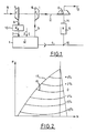
- Figure 1 illustrates a traditional compound engine.
- An internal combustion engine 1 is a machine which transforms an oxidizer 2 and a fuel 3 into mechanical energy collected on a rotating shaft 4. It also produces, and among other things, exhaust gases 5 containing a significant proportion of the energy introduced in 3. Part of this energy can be recovered on a turbine 6 which drives a compressor 7. The latter sucks atmospheric air 8 and compresses it to force-feed the engine. The compressed air 9 can optionally be cooled in an exchanger 10 to lower the pressures in the engine for a given job.
- the supercharging system 6 and 7 may or may not exist, just like the cooler 10.
- This device makes it possible to recover energy but at the cost of a pressure drop which compromises the operation of the upstream stage, that is to say the engine if it is not supercharged, and the latter and its turbo-compressor in the opposite case.
- the full load curve 17 delimits the possible operating range of the engine.
- the influence of the compound on the overall yield is favorable for high speeds and loads, and unfavorable for low loads and low speeds. If the vehicle which is equipped with such an engine has a power much higher than the power necessary for running, the engine is frequently used at low loads and the general balance of the compound is unfavorable.
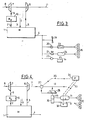
- a certain number of machines are driven by the motor shaft 4 to produce the on-board assistance energies. These are for example, as illustrated in FIG. 3, the cooling fan 19, the hydraulic pump 20 for steering assistance, the air compressor 21 for braking assistance, the alternator 22 for supplying the batteries. , etc ..., without this list of assistance cited as an example being exhaustive.
- the different machines thus driven flow either in a radiator, or in hydraulic or electric accumulators, or in pressure tanks.
- the energy can then be delivered at the appropriate time to the machines 26 which need it for the various on-board assistances.
- the energy drawn from the shaft 4 is noble and all the more expensive as it is withdrawn at low load from the motor shaft. Under these conditions, the engine efficiency is at its lowest and a joule on the engine shaft can "cost" 5 joules or more in the fuel tank.
- the overall energy balance can therefore be improved if, by a compound system, energy is recovered from the exhaust gases for the sole need of assistance energies.
- a 3-way valve 27 is placed on the exhaust pipe 11 and diverts part or all of the flow towards a turbine 28 before directing it towards the exhaust 13.
- the turbine 28 drives, directly or by means of a speed reducer, an electric alternator 30 which flows, when energized, to a battery 32, and a hydraulic pump or air compressor 29 (or both) which flows or (flow) to accumulators or tanks air 31.
- the assistance machines 26 are supplied normally from the battery 32 and the air accumulators 31.
- the states of charge of the battery 32 and of the pressure of the tanks 31 are measured and the information 33 transmitted to a microprocessor 34.
- a command and an actuator 35 it operates the valve 27.
- the microprocessor can thus be programmed to satisfy the various requirements which one imposes on the drawing of energy on 11, for example, but any other logic can be envisaged: - we respond to all priority safety requests (exhaustion of brake, steering assistance, etc.), - the energy available for the various other assistance devices is only stored when the engine operating point on its usage diagram (fig. 2) is in the gains zone, - we privilege certain scenarios according to various operating criteria, -etc ...
Abstract
Description
La présente invention se rapporte à un moteur dit compound adapté du type récupérant de l'énergie sur le flux de gaz d'échappement. L'énergie récupérée sert à alimenter l'arbre moteur, ou à entraîner diverses machines auxiliaires.The present invention relates to a so-called suitable compound engine of the type recovering energy from the exhaust gas flow. The recovered energy is used to power the motor shaft, or to drive various auxiliary machines.
Suivant une particularité essentielle, ce moteur qui comporte une turbine montée sur une tubulure d'échappement, incorpore une vanne trois voies placée sur cette tubulure pour dériver tout ou partie du flux gazeux vers cette turbine avant de le diriger vers l'échappement.According to an essential characteristic, this engine which comprises a turbine mounted on an exhaust manifold, incorporates a three-way valve placed on this manifold to divert all or part of the gas flow towards this turbine before directing it towards the exhaust.
Cette conception permet d'améliorer le bilan énergétique global en récupérant de l'énergie sur les gaz d'échappement pour le seul besoin des énergies d'assistance.This design improves the overall energy balance by recovering energy from the exhaust gases for the sole need of assistance energies.
D'autres particularités et avantages de l'invention ressortiront plus clairement de la description qui suit d'un mode de réalisation préféré, donné à titre d'exemple non limitatif, en référence aux dessins annexés dans lesquels :
- - La figure 1 représente un croquis d'un moteur compound conventionnel,
- - La figure 2 représente un diagramme puissance en fonction du régime, propre à ce moteur,
- - La figure 3 représente un croquis d'un moteur suralimenté dont l'arbre moteur entraîne diverses machines d'assistance de bord,
- - et la figure 4 représente un croquis d'un moteur compound adapté conforme à l'invention.
- - Figure 1 shows a sketch of a conventional compound engine,
- FIG. 2 represents a power diagram as a function of the speed, specific to this engine,
- FIG. 3 represents a sketch of a supercharged engine whose engine shaft drives various on-board assistance machines,
- - And Figure 4 shows a sketch of a suitable compound engine according to the invention.
La figure 1 illustre un moteur compound traditionnel.Figure 1 illustrates a traditional compound engine.
Un moteur thermique à combustion interne 1 est une machine qui transforme un comburant 2 et un carburant 3 en énergie mécanique recueillie sur un arbre tournant 4. Il produit de plus et entre autre chose, des gaz d'échappement 5 contenant une part importante de l'énergie introduite en 3. Une partie de cette énergie peut être récupérée sur une turbine 6 qui entraîne un compresseur 7. Celui-ci aspire l'air atmosphérique 8 et le comprime pour en gaver le moteur. L'air comprimé 9 peut éventuellement être refroidi dans un échangeur 10 pour abaisser les pressions dans le moteur pour un travail donné.An internal combustion engine 1 is a machine which transforms an
Le système de suralimentation 6 et 7 peut ou non exister, tout comme le refroidisseur 10.The
Dans tous les cas, il reste sur le flux de gaz d'échappement 11, une quantité d'énergie plus ou moins importante.In all cases, there remains on the flow of
Diverses solutions de récupération de cette énergie existent, et notamment le système dit compound. Il consiste en l'installation d'une turbine 12 en plein flux sur l'échappement 11. L'énergie récupérée en 12 est utilisée, soit en la dirigeant au travers d'un réducteur de vitesse et d'une roue libre 15 vers l'arbre moteur 16, soit pour entraîner diverses machines auxiliaires.Various solutions for recovering this energy exist, and in particular the so-called compound system. It consists of installing a
Ce dispositif permet de récupérer de l'énergie mais au prix d'une perte de charge qui compromet le fonctionnement de l'étage amont, c'est-à-dire le moteur s'il n'est pas suralimenté, et celui-ci et son turbo-compresseur dans le cas contraire.This device makes it possible to recover energy but at the cost of a pressure drop which compromises the operation of the upstream stage, that is to say the engine if it is not supercharged, and the latter and its turbo-compressor in the opposite case.
Sur le diagramme puissance en fonction du régime représenté à la figure 2, la courbe de pleine charge 17 délimite la plage de fonctionnement possible du moteur. Les courbes d'iso-influence de la perte de charge du compound sur échappement 18, séparent les plages où sa présence est favorable et améliorent le rendement de celles où elle est défavorable et détériorent le rendement.On the power diagram as a function of the speed shown in FIG. 2, the
En général, l'influence du compound sur le rendement global est favorable aux régimes et aux charges élevées, et défavorable aux faibles charges et bas régimes. Si le véhicule qui est équipé d'un tel moteur dispose d'une puissance très supérieure à la puissance nécessaire au roulage, le moteur est fréquemment utilisé à faibles charges et le bilan général du compound est défavorable.In general, the influence of the compound on the overall yield is favorable for high speeds and loads, and unfavorable for low loads and low speeds. If the vehicle which is equipped with such an engine has a power much higher than the power necessary for running, the engine is frequently used at low loads and the general balance of the compound is unfavorable.
Par ailleurs, un certain nombre de machines sont entraînées par l'arbre moteur 4 pour produire les énergies d'assistance de bord. Ce sont par exemple, comme l'illustre la figure 3, le ventilateur 19 de refroidissement, la pompe hydraulique 20 d'assistance de direction, le compresseur d'air 21 d'assistance de freinage, l'alternateur 22 d'alimentation des batteries, etc..., sans que cette liste d'assistance citée à titre d'exemple ne soit limitative.In addition, a certain number of machines are driven by the
Les différentes machines ainsi entraînées débitent, soit dans un radiateur, soit dans des accumulateurs hydrauliques ou électriques, soit dans des réservoirs sous pression. L'énergie peut alors être délivrée au moment opportun vers les machines 26 qui en ont besoin pour les différentes assistances de bord.The different machines thus driven flow either in a radiator, or in hydraulic or electric accumulators, or in pressure tanks. The energy can then be delivered at the appropriate time to the
L'énergie puisée sur l'arbre 4 est noble et d'autant plus chère qu'elle est soustraite à faible charge à l'arbre moteur. Dans ces conditions, le rendement du moteur est au plus bas et un joule sur l'arbre moteur peut "coûter" 5 joules ou plus dans le réservoir de carburant.The energy drawn from the
Le bilan énergétique global peut donc être amélioré si, par un système compound, on récupère de l'énergie sur les gaz d'échappement pour le seul besoin des énergies d'assistance.The overall energy balance can therefore be improved if, by a compound system, energy is recovered from the exhaust gases for the sole need of assistance energies.
Pour éviter de tomber sur les difficultés soulevées par un système compound classique, on peut imaginer un compound adapté qui fonctionne comme suit, en référence à la figure 4 :To avoid falling on the difficulties raised by a conventional compound system, one can imagine a suitable compound which works as follows, with reference to Figure 4:
Une vanne 3 voies 27 est placée sur la tubulure d'échappement 11 et dérive un partie ou la totalité du flux vers une turbine 28 avant de le diriger vers l'échappement 13. La turbine 28 entraîne, directement ou par l'intermédiaire d'une réducteur de vitesse, un alternateur électrique 30 qui débite, lorsqu'il est excité, vers une batterie 32, et une pompe hydraulique ou un compresseur d'air 29 (ou les deux) qui débite ou (débitent) vers les accumulateurs ou réservoirs d'air 31.A 3-
Les machines d'assistance 26 sont alimentées normalement à partir de la batterie 32 et des accumulateurs d'air 31. Les états de charge de la batterie 32 et de pression des réservoirs 31 sont mesurés et les informations 33 transmises à un microprocesseur 34. Par une commande et un actionneur 35, il manoeuvre la vanne 27.The
Le microprocesseur peut ainsi être programmé pour satisfaire aux diverses exigences qu'on impose au puisage d'énergie sur 11, par exemple, mais tout autre logique peut être envisagée :
- on répond à toute demande de sécurité en priorité (épuisement assistance des freins, de la direction...),
- on ne stocke l'énergie disponible pour les diverses autres assistances que lorsque le point de fonctionnement du moteur sur son diagramme d'utilisation (fig. 2) est dans la zone des gains,
- on privilègie certains scénaris en fonction de critères de fonctionnement divers,
-etc...The microprocessor can thus be programmed to satisfy the various requirements which one imposes on the drawing of energy on 11, for example, but any other logic can be envisaged:
- we respond to all priority safety requests (exhaustion of brake, steering assistance, etc.),
- the energy available for the various other assistance devices is only stored when the engine operating point on its usage diagram (fig. 2) is in the gains zone,
- we privilege certain scenarios according to various operating criteria,
-etc ...
Il va de soi qu'on pourra jouer sur la capacité des réserves (batteries, réservoirs, accumulateurs...). Plus ces capacités seront importantes, et plus le choix des séquences de puisage d'énergie sera aisé.It goes without saying that we can play on the capacity of reserves (batteries, tanks, accumulators ...). The larger these capacities, the easier the choice of energy drawing sequences.
Différentes variantes peuvent être envisagées : à titre d'exemple :
- Seulement une machine entraînée par la turbine, au lieu de deux ou trois,
- Compresseur centrifuge mono-étagé aspirant en 9 entraîné par la turbine.
- Compresseur centrifuge bi-étagé aspirant à l'atmosphère,
- Décharge du réservoir 31 dans 9 lors d'une reprise à bas régime.Different variants can be envisaged: for example:
- Only one machine driven by the turbine, instead of two or three,
- Single-stage centrifugal compressor aspirating at 9 driven by the turbine.
- Two-stage centrifugal compressor aspirating to the atmosphere,
- Discharge of the
Claims (1)
Applications Claiming Priority (2)
| Application Number | Priority Date | Filing Date | Title |
|---|---|---|---|
| FR8814113 | 1988-10-28 | ||
| FR8814113A FR2638487B1 (en) | 1988-10-28 | 1988-10-28 | COMPOUND MOTOR ADAPTED |
Publications (2)
| Publication Number | Publication Date |
|---|---|
| EP0366536A1 true EP0366536A1 (en) | 1990-05-02 |
| EP0366536B1 EP0366536B1 (en) | 1993-10-06 |
Family
ID=9371384
Family Applications (1)
| Application Number | Title | Priority Date | Filing Date |
|---|---|---|---|
| EP89402920A Expired - Lifetime EP0366536B1 (en) | 1988-10-28 | 1989-10-24 | Adapted compound engine |
Country Status (4)
| Country | Link |
|---|---|
| EP (1) | EP0366536B1 (en) |
| DE (1) | DE68909737T2 (en) |
| ES (1) | ES2044181T3 (en) |
| FR (1) | FR2638487B1 (en) |
Cited By (1)
| Publication number | Priority date | Publication date | Assignee | Title |
|---|---|---|---|---|
| WO2000043652A1 (en) * | 1999-01-20 | 2000-07-27 | Galin Stefanov Raychinov | Integral multifunctional system for motor vehicle |
Citations (3)
| Publication number | Priority date | Publication date | Assignee | Title |
|---|---|---|---|---|
| US3513929A (en) * | 1967-08-25 | 1970-05-26 | Exxon Research Engineering Co | Low-polluting engine and drive system |
| GB2080432A (en) * | 1980-07-22 | 1982-02-03 | South Western Ind Res | Differential compound engine |
| DE3728681A1 (en) * | 1986-08-29 | 1988-03-10 | Isuzu Motors Ltd | TURBO COMPOSITION ENGINE |
Family Cites Families (1)
| Publication number | Priority date | Publication date | Assignee | Title |
|---|---|---|---|---|
| US4694654A (en) * | 1983-10-29 | 1987-09-22 | Isuzu Motors Limited | Exhaust energy recovery and generator for use with an engine |
-
1988
- 1988-10-28 FR FR8814113A patent/FR2638487B1/en not_active Expired - Lifetime
-
1989
- 1989-10-24 ES ES89402920T patent/ES2044181T3/en not_active Expired - Lifetime
- 1989-10-24 DE DE89402920T patent/DE68909737T2/en not_active Expired - Fee Related
- 1989-10-24 EP EP89402920A patent/EP0366536B1/en not_active Expired - Lifetime
Patent Citations (3)
| Publication number | Priority date | Publication date | Assignee | Title |
|---|---|---|---|---|
| US3513929A (en) * | 1967-08-25 | 1970-05-26 | Exxon Research Engineering Co | Low-polluting engine and drive system |
| GB2080432A (en) * | 1980-07-22 | 1982-02-03 | South Western Ind Res | Differential compound engine |
| DE3728681A1 (en) * | 1986-08-29 | 1988-03-10 | Isuzu Motors Ltd | TURBO COMPOSITION ENGINE |
Cited By (2)
| Publication number | Priority date | Publication date | Assignee | Title |
|---|---|---|---|---|
| WO2000043652A1 (en) * | 1999-01-20 | 2000-07-27 | Galin Stefanov Raychinov | Integral multifunctional system for motor vehicle |
| US6539711B1 (en) | 1999-01-20 | 2003-04-01 | Galin Stefanov Raychinov | Integral multifunctional system for motor vehicle |
Also Published As
| Publication number | Publication date |
|---|---|
| FR2638487B1 (en) | 1993-11-26 |
| EP0366536B1 (en) | 1993-10-06 |
| FR2638487A1 (en) | 1990-05-04 |
| ES2044181T3 (en) | 1994-01-01 |
| DE68909737D1 (en) | 1993-11-11 |
| DE68909737T2 (en) | 1994-03-03 |
Similar Documents
| Publication | Publication Date | Title |
|---|---|---|
| US7849840B2 (en) | Electric motor assisted mechanical supercharging system | |
| US6782849B2 (en) | Cooling system for an internal combustion engine | |
| EP0396754A1 (en) | Power transmission for supercharger-carrying internal combustion engines | |
| EP1302731B1 (en) | Device for the thermal control of a car | |
| EP0091356B1 (en) | Energy recuperation method in a power plant, and power plant using said method | |
| GB2090913A (en) | Turbocharged ic engine with an auxiliary charge compressor | |
| FR2830926A1 (en) | Thermal regulator air-conditioner of electrical or hybrid automobile, has secondary heat exchange circuit connected to automobile heat generating sources, with evaporators in principal circuit having up stream trigger valves | |
| FR2508974A1 (en) | METHOD AND DEVICE FOR CONTROLLING THE EXHAUST DISCHARGE VALVE OF A TURBOCHARGED INTERNAL COMBUSTION ENGINE | |
| CA2641962A1 (en) | Improvement to rotorcrafts equipped with turbine engines | |
| FR2764348A1 (en) | HYDRAULIC DRIVE ASSEMBLY FOR ASSISTING AUXILIARY FUNCTIONS IN MOTOR VEHICLES, AND METHOD FOR CONTINUOUSLY ADJUSTING THE DELIVERY OF A PUMP FOR AN AUXILIARY DEVICE | |
| FR2479899A1 (en) | TURBOCHARGER FOR INTERNAL COMBUSTION ENGINE AND METHOD FOR THE USE THEREOF | |
| EP0366536B1 (en) | Adapted compound engine | |
| US20190186348A1 (en) | Electrically-assisted turbocharger | |
| US1277735A (en) | Cooling system. | |
| EP0779419B1 (en) | Improvements made in the engine assembly of automotive vehicles | |
| FR2483517A1 (en) | MOTOR VEHICLE PROVIDED WITH AN EXHAUST GAS ENERGY CONVERSION DEVICE INTO ELECTRICITY | |
| FR2846383A1 (en) | ELECTRIC PUMP FOR POOL MAINTENANCE | |
| SE509524C2 (en) | Internal combustion engine with AT controller | |
| US6082975A (en) | Cold turbocharger consisting of a low mass turbine single disk unit | |
| FR2495689A1 (en) | Coolant circuit for diesel engine - has heat exchanger in air intake for recuperator air and fuel circuit | |
| FR2560289A1 (en) | Mixed ''normally aspirated/supercharged'' inlet system for an internal combustion engine | |
| JPS59203860A (en) | Supercharged suction air introducing device of internal- combustion engine for vehicle | |
| JPH0882220A (en) | Turbo charger | |
| JP2819952B2 (en) | Intake energy recovery system for internal combustion engine | |
| FR2479896A1 (en) | Exhaust turbine driven generator for IC engine - recovers energy from exhaust gases to drive a generator which supplies vehicles electric equipment |
Legal Events
| Date | Code | Title | Description |
|---|---|---|---|
| PUAI | Public reference made under article 153(3) epc to a published international application that has entered the european phase |
Free format text: ORIGINAL CODE: 0009012 |
|
| 17P | Request for examination filed |
Effective date: 19891027 |
|
| AK | Designated contracting states |
Kind code of ref document: A1 Designated state(s): DE ES GB IT NL SE |
|
| 17Q | First examination report despatched |
Effective date: 19920110 |
|
| GRAA | (expected) grant |
Free format text: ORIGINAL CODE: 0009210 |
|
| AK | Designated contracting states |
Kind code of ref document: B1 Designated state(s): DE ES GB IT NL SE |
|
| ITF | It: translation for a ep patent filed |
Owner name: JACOBACCI CASETTA & PERANI S.P.A. |
|
| REF | Corresponds to: |
Ref document number: 68909737 Country of ref document: DE Date of ref document: 19931111 |
|
| GBT | Gb: translation of ep patent filed (gb section 77(6)(a)/1977) |
Effective date: 19931021 |
|
| REG | Reference to a national code |
Ref country code: ES Ref legal event code: FG2A Ref document number: 2044181 Country of ref document: ES Kind code of ref document: T3 |
|
| PLBE | No opposition filed within time limit |
Free format text: ORIGINAL CODE: 0009261 |
|
| STAA | Information on the status of an ep patent application or granted ep patent |
Free format text: STATUS: NO OPPOSITION FILED WITHIN TIME LIMIT |
|
| 26N | No opposition filed | ||
| EAL | Se: european patent in force in sweden |
Ref document number: 89402920.6 |
|
| REG | Reference to a national code |
Ref country code: GB Ref legal event code: IF02 |
|
| PGFP | Annual fee paid to national office [announced via postgrant information from national office to epo] |
Ref country code: DE Payment date: 20071018 Year of fee payment: 19 Ref country code: ES Payment date: 20071120 Year of fee payment: 19 Ref country code: NL Payment date: 20070923 Year of fee payment: 19 |
|
| PGFP | Annual fee paid to national office [announced via postgrant information from national office to epo] |
Ref country code: IT Payment date: 20071026 Year of fee payment: 19 |
|
| PGFP | Annual fee paid to national office [announced via postgrant information from national office to epo] |
Ref country code: SE Payment date: 20071004 Year of fee payment: 19 |
|
| PGFP | Annual fee paid to national office [announced via postgrant information from national office to epo] |
Ref country code: GB Payment date: 20071024 Year of fee payment: 19 |
|
| EUG | Se: european patent has lapsed | ||
| GBPC | Gb: european patent ceased through non-payment of renewal fee |
Effective date: 20081024 |
|
| NLV4 | Nl: lapsed or anulled due to non-payment of the annual fee |
Effective date: 20090501 |
|
| PG25 | Lapsed in a contracting state [announced via postgrant information from national office to epo] |
Ref country code: NL Free format text: LAPSE BECAUSE OF NON-PAYMENT OF DUE FEES Effective date: 20090501 |
|
| PG25 | Lapsed in a contracting state [announced via postgrant information from national office to epo] |
Ref country code: IT Free format text: LAPSE BECAUSE OF NON-PAYMENT OF DUE FEES Effective date: 20081024 Ref country code: DE Free format text: LAPSE BECAUSE OF NON-PAYMENT OF DUE FEES Effective date: 20090501 |
|
| PG25 | Lapsed in a contracting state [announced via postgrant information from national office to epo] |
Ref country code: GB Free format text: LAPSE BECAUSE OF NON-PAYMENT OF DUE FEES Effective date: 20081024 |
|
| REG | Reference to a national code |
Ref country code: ES Ref legal event code: FD2A Effective date: 20081025 |
|
| PG25 | Lapsed in a contracting state [announced via postgrant information from national office to epo] |
Ref country code: ES Free format text: LAPSE BECAUSE OF NON-PAYMENT OF DUE FEES Effective date: 20081025 |
|
| PG25 | Lapsed in a contracting state [announced via postgrant information from national office to epo] |
Ref country code: SE Free format text: LAPSE BECAUSE OF NON-PAYMENT OF DUE FEES Effective date: 20081025 |