EP0366527A1 - Sicherheitssystem mit funkelektrischer Übertragung - Google Patents
Sicherheitssystem mit funkelektrischer Übertragung Download PDFInfo
- Publication number
- EP0366527A1 EP0366527A1 EP89402891A EP89402891A EP0366527A1 EP 0366527 A1 EP0366527 A1 EP 0366527A1 EP 89402891 A EP89402891 A EP 89402891A EP 89402891 A EP89402891 A EP 89402891A EP 0366527 A1 EP0366527 A1 EP 0366527A1
- Authority
- EP
- European Patent Office
- Prior art keywords
- signals
- alarm
- transmitter
- transmission
- signal
- Prior art date
- Legal status (The legal status is an assumption and is not a legal conclusion. Google has not performed a legal analysis and makes no representation as to the accuracy of the status listed.)
- Granted
Links
Images
Classifications
-
- G—PHYSICS
- G08—SIGNALLING
- G08B—SIGNALLING OR CALLING SYSTEMS; ORDER TELEGRAPHS; ALARM SYSTEMS
- G08B29/00—Checking or monitoring of signalling or alarm systems; Prevention or correction of operating errors, e.g. preventing unauthorised operation
- G08B29/16—Security signalling or alarm systems, e.g. redundant systems
-
- G—PHYSICS
- G08—SIGNALLING
- G08B—SIGNALLING OR CALLING SYSTEMS; ORDER TELEGRAPHS; ALARM SYSTEMS
- G08B25/00—Alarm systems in which the location of the alarm condition is signalled to a central station, e.g. fire or police telegraphic systems
- G08B25/01—Alarm systems in which the location of the alarm condition is signalled to a central station, e.g. fire or police telegraphic systems characterised by the transmission medium
- G08B25/10—Alarm systems in which the location of the alarm condition is signalled to a central station, e.g. fire or police telegraphic systems characterised by the transmission medium using wireless transmission systems
Definitions
- the invention relates to security systems, that is to say, danger warning systems which signal dangers such as for example a break-in, theft, fire, smoke, gas, etc. It relates more particularly to security systems in which the signaling or transmission of danger information and control orders for the security systems is carried out by radio means.
- danger information also called “events”
- Wired links are normally monitored, that is to say that they include devices to detect anomalies which prevent the transmission of events such as interruption, short-circuit, earthing, which makes the system capable of continuously transmitting safety-related signals.
- the transmitters are of the autonomous type, i.e. they have their own source of energy which is unique and which is not backed up, i.e. -to say that there is no backup source. Consequently, a permanent transmission of signals would involve the use of energy sources whose volume, weight and cost are prohibitive in the state of the art.
- the legislation currently in force does not allow permanent occupation of the radio frequency bands, but only of the order of thirty seconds every five minutes, and it is therefore necessary to distribute the test signals over time. system.
- the object of the present invention is therefore to provide a radio transmission security system which has operating security compatible with the standards in force while respecting the constraints indicated above.
- the goal is achieved by ensuring the transmission of information, instead of monitoring the proper functioning of the transmission.
- the invention proposes to use at least two transmission devices, each transmitting the same information signals, with the exception of the identity of the transmission device, on the same frequency to a single receiver. but shifted in time relative to each other.
- the detection of two identical and offset signals makes it possible to validate the information received and the detection of a single signal gives the information, but also indicates the existence of a fault in a determined transmission device .
- the invention relates to a security system with radio transmission in which each alarm detection device is associated with a transmitter and in which several transmitters are associated with a single receiver characterized in that each transmitter comprises at least two identical transmission devices designed to receive the output signals of the alarm detection device and transmit on the same transmission frequency at least two substantially identical signals which are time-shifted by a determined time so as to transmit to the single receiver at least one alarm signal in the event of failure of an emission device.
- the system is also characterized in that the single receiver includes a logic circuit for comparing the signals transmitted by a transmitter and providing signals indicating the type of alarm as well as possibly the identity of the transmission device which is faulty.
- the invention also relates to a method for ensuring the transmission of an alarm signal in a radio transmission security system in which each alarm detection device is associated with a transmitter and in which several transmitters are associated with a single receiver, characterized in that it comprises the following operations: - the development of two identical alarm signals in two separate devices, - the transmission by said devices of two alarm transmission signals separated by a determined time interval, - the reception of at least one of the two signals transmitted to determine the alarm which gave rise to said signal, and - comparing the signals received so as to determine the device which is faulty.
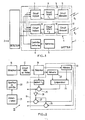
- the security system comprises a plurality of transmitters 1, a number N for example, which are in radio link with a single receiver 15 (FIG. 2).
- Each transmitter 1, associated with an alarm or event detection device 2 comprises two identical emission devices 3 and 4, an autonomous electrical supply device 5 of the battery type and a battery control device 6.
- Each transmission device 3 (or 4) comprises a logic circuit 7 (or 8), a delay circuit 9 (or 10) and a transmission circuit proper 11 (or 12).
- Each logic circuit 7 or 8 receives the alarm signal or signals supplied by the detection device 2, including the alarm signal corresponding to the possible displacement of the transmitter 1. It also receives an alarm signal relating to the state of the power supply device 5.
- each logic circuit 7 or 8 On the basis of the signals received, each logic circuit 7 or 8 provides an output signal S1 or S2 only if the received signals correspond to an alarm detected by the detection device 2 or the battery control device 6.
- the signals S1 and S2 are of the coded type so as to indicate in particular the type of alarm and the identity of the transmission device concerned.
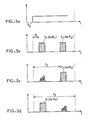
- the signal S1 is delayed by a duration t1 in the delay circuit 9 and this delayed signal S′1 is transmitted by the transmission circuit 11 (radio signal E1).
- the signal S2 is delayed by a duration t2 in the delay circuit 10 and this delayed signal S′2 is transmitted by the transmission circuit 12 (radio signal E2).
- the receiver 15 of the security system comprises, as shown in the functional diagram of FIG. 2, a circuit 16 for receiving the radio signals E1 and E2, a circuit for shaping 17 the signals received E1 and E2 for obtaining signals R1 and R2 respectively, a decoding circuit 18 of the signals R1 and R2 and a decision logic circuit 19. It further comprises a transmitter 20 which is used to control the proper functioning of the reception circuit 16 and a device power supply 21 of the back-up type, that is to say operating continuously with the desired security.
- the decoding circuit 18 (or decoder) notably determines the origin of the signal received, that is to say the identity of the transmission device which transmitted it thanks to the code contained in the signal E1 or E2.
- the logic circuit 19 of the receiver 15 includes a first memory 22 for recording the received signal R1 and a second memory 23 for recording the received signal R2.
- the referral to one or the other memory 22 or 23 is obtained by the code of the identity of the transmission device concerned.
- the contents of these two memories are compared in a comparator 24 which provides a signal indicating the identity or not of the signals R1 and R2 (apart from the code part giving the identity of the transmission device).
- the output terminal of the comparator 24 is connected to an input terminal of an AND logic circuit 25 the other input terminal of which is connected to a delay circuit 29 of duration t3 equal to the maximum duration of reception of the receiver 15, counted from the moment of reception of the signal E1, the first to date.
- the output signal from comparator 24 is only taken into account at the end of the duration t3.
- the duration t3 must obviously be much greater than t2 - t1. If at the end of the duration t3, the two signals R1 and R2 are identical, the comparator signal will be taken into account and will mean that there is an alarm signal from the transmitter 1 and that all works correctly. On the other hand, if at the end of the duration t3, one of the two signals R1 and R2 exists alone, this will also mean that there is an alarm signal from the transmitter 1 and that there is a fault in one of the two transmitting devices 3 and 4.
- the signal E1 or E2 which is received.
- This determination can be made using the AND circuits 26 and 27, one of the input terminals of which is connected to the output terminal of the AND circuit 25 via an inverter 28.
- the other input terminal of the AND circuit 26 is connected to memory 22 (signal R1) while the other input terminal of the AND circuit 27 is connected to memory 23 (signal R3), the two signals coming from memories 22 and 23 indicating the presence or 'absence of signals R1 and R2.
- the signal R1 is absent, the circuits AND 25 and 26 will be closed while the AND circuit 27 will be open, which will indicate that the transmitting device 3 has failed.
- the signal R2 is absent, the AND circuits 25 and 27 will be closed while the AND circuit 26 will be open, which will indicate that the transmission device 4 has failed.
- control transmitter transmits signals which are received by said receiver.
- the received signals are analyzed in the same way as the alarm signals from the transmitting devices 3 and 4. This analysis makes it possible to determine a possible failure of the receiver.
- the signals S1, S2 which are produced by the logic circuits 7 and 8 and therefore the transmitted signals E1, E2 are made up of codes which identify in particular the transmitter, the type of alarm and the identity of the transmission device concerned.
- the analysis of signals received that is to say signals E1 or E2 recorded respectively in memories 22 and 23, makes it possible to determine the transmitter in question as well as the type of alarm, for example a battery whose voltage is lower than a certain security threshold.
- the security system according to the invention has been described by showing only one transmitter, but it is understood that it can be implemented with a very high number of transmitters for the same single frequency receiver, all the transmitters being identical except for their identification code.
- the security system has the following advantages: -
- the power supply device of the transmitter consumes energy significantly only when there is an event to transmit because the electrical consumption of the logic circuits is very low compared to that of the circuits d 'program.
- a fault in one of the transmission devices does not prevent the transmission of events, only confirmation of the event is not possible.
- Monitoring of the receiver's operation is ensured via the control transmitter associated with it.
- the probable and imminent failure of the transmission devices as a result of a faulty supply device can be detected preventively.
- the invention has been described with a transmitter comprising two transmission devices 3 and 4 but it is clear that it also applies to a transmitter comprising more than two transmission devices in the event that it is desired to obtain a greater transmission guarantee.
Landscapes
- Engineering & Computer Science (AREA)
- Computer Security & Cryptography (AREA)
- Physics & Mathematics (AREA)
- General Physics & Mathematics (AREA)
- Computer Networks & Wireless Communication (AREA)
- Business, Economics & Management (AREA)
- Emergency Management (AREA)
- Alarm Systems (AREA)
- Transceivers (AREA)
- Fire Alarms (AREA)
- Helmets And Other Head Coverings (AREA)
Priority Applications (1)
| Application Number | Priority Date | Filing Date | Title |
|---|---|---|---|
| AT89402891T ATE87385T1 (de) | 1988-10-25 | 1989-10-19 | Sicherheitssystem mit funkelektrischer uebertragung. |
Applications Claiming Priority (2)
| Application Number | Priority Date | Filing Date | Title |
|---|---|---|---|
| FR8813920 | 1988-10-25 | ||
| FR8813920A FR2638267B1 (fr) | 1988-10-25 | 1988-10-25 | Systeme de securite a transmission radioelectrique |
Publications (2)
| Publication Number | Publication Date |
|---|---|
| EP0366527A1 true EP0366527A1 (de) | 1990-05-02 |
| EP0366527B1 EP0366527B1 (de) | 1993-03-24 |
Family
ID=9371248
Family Applications (1)
| Application Number | Title | Priority Date | Filing Date |
|---|---|---|---|
| EP89402891A Expired - Lifetime EP0366527B1 (de) | 1988-10-25 | 1989-10-19 | Sicherheitssystem mit funkelektrischer Übertragung |
Country Status (4)
| Country | Link |
|---|---|
| EP (1) | EP0366527B1 (de) |
| AT (1) | ATE87385T1 (de) |
| DE (1) | DE68905567T2 (de) |
| FR (1) | FR2638267B1 (de) |
Citations (4)
| Publication number | Priority date | Publication date | Assignee | Title |
|---|---|---|---|---|
| US3848231A (en) * | 1970-12-31 | 1974-11-12 | Baldwin Electronics Inc | Alarm system utilizing pulse position modulation and dual conductor sensor |
| US3909722A (en) * | 1973-06-22 | 1975-09-30 | Jbh Electronic Systems Inc | Variable frequency communication system |
| EP0155773A2 (de) * | 1984-02-27 | 1985-09-25 | Pittway Corporation | Kommunikationssystem |
| US4665385A (en) * | 1985-02-05 | 1987-05-12 | Henderson Claude L | Hazardous condition monitoring system |
-
1988
- 1988-10-25 FR FR8813920A patent/FR2638267B1/fr not_active Expired - Lifetime
-
1989
- 1989-10-19 DE DE8989402891T patent/DE68905567T2/de not_active Expired - Fee Related
- 1989-10-19 EP EP89402891A patent/EP0366527B1/de not_active Expired - Lifetime
- 1989-10-19 AT AT89402891T patent/ATE87385T1/de active
Patent Citations (4)
| Publication number | Priority date | Publication date | Assignee | Title |
|---|---|---|---|---|
| US3848231A (en) * | 1970-12-31 | 1974-11-12 | Baldwin Electronics Inc | Alarm system utilizing pulse position modulation and dual conductor sensor |
| US3909722A (en) * | 1973-06-22 | 1975-09-30 | Jbh Electronic Systems Inc | Variable frequency communication system |
| EP0155773A2 (de) * | 1984-02-27 | 1985-09-25 | Pittway Corporation | Kommunikationssystem |
| US4665385A (en) * | 1985-02-05 | 1987-05-12 | Henderson Claude L | Hazardous condition monitoring system |
Non-Patent Citations (1)
| Title |
|---|
| PATENT ABSTRACTS OF JAPAN * |
Also Published As
| Publication number | Publication date |
|---|---|
| ATE87385T1 (de) | 1993-04-15 |
| FR2638267A1 (fr) | 1990-04-27 |
| DE68905567T2 (de) | 1993-08-26 |
| FR2638267B1 (fr) | 1990-12-21 |
| DE68905567D1 (de) | 1993-04-29 |
| EP0366527B1 (de) | 1993-03-24 |
Similar Documents
| Publication | Publication Date | Title |
|---|---|---|
| EP0094279B1 (de) | Verfahren zum Schutz eines Fernüberwachungssystemes gegen Sabotage und System zur Ausführung dieses Verfahrens | |
| EP0335799B1 (de) | Elektronische Methoden und Schaltungen zur drahtgebundenen Fernabfrage von elektrischen Empfänger | |
| EP0366527B1 (de) | Sicherheitssystem mit funkelektrischer Übertragung | |
| EP0612016B1 (de) | Verfahren und Anordnung zum Schutz eines seriellen Bus gegen Kurzschluss | |
| EP0570289A1 (de) | Einrichtung zur Detektion der Durchfahrt eines Fahrzeuges mittels eines passiven Transponders | |
| FR2645304A1 (fr) | Systeme de surveillance d'installations industrielles | |
| EP1645483A1 (de) | System zur automatischen Warnung vor Zügen | |
| EP0236170A1 (de) | Gebietsfernüberwachungsvorrichtung und -verfahren mit Mitteln zur Detektion anormaler Vorfälle, Hörmittel und Videobeobachtungsmittel | |
| EP0199294B1 (de) | Verfahren und Anordnung zur Signalisierung über eine bidirektionale digitale Übertragungsstrecke | |
| CA1205893A (fr) | Interface pour relier un systeme informatique a un dispositif actionneur | |
| FR2890507A1 (fr) | Procede de commande de la vitesse de communication sur un bus lin. | |
| EP1817870B1 (de) | Verfahren zur überwachung des betriebs eines telekommunikationsendgerätes in einem faseroptischen telekommunikationsnetzwerk | |
| FR2643481A1 (fr) | Procede et dispositif de transmission d'informations entre stations d'un reseau de communication, notamment pour vehicule automobile | |
| EP0011014B1 (de) | Vorrichtung zur Messung der Qualität einer digitalen Verbindungsstrecke und eine solche Vorrichtung enthaltende Übertragungseinrichtungen | |
| EP3672359A1 (de) | Elektrisches gerät, das im alternativen betrieb auf ein mobiltelefonnetz zugreift | |
| FR2556103A1 (fr) | Station terrestre d'un systeme de navigation | |
| EP0184108A1 (de) | Verfahren und Anordnung zur Signalisierung für eine digitale Verbindungsleitung durch Ersetzen von übertragenen Daten durch Berichte | |
| FR2830703A1 (fr) | Point de commande et procede de transmission de donnees avec un point de commande | |
| EP0367688A1 (de) | Verfahren und Anordnung zur Ermittlung einer Unterbrechung in einer Übertragungsverbindung | |
| FR2695780A1 (fr) | Procédé de détection d'un court-circuit entre les lignes d'un bus transmettant des données numériques sous forme de signaux différentiels de tension. | |
| EP0053051B1 (de) | Verfahren zum Übertragen von Betriebssignalen einer digitalen Richtfunkstrecke, Sender und Empfänger zur Durchführung eines solchen Verfahrens | |
| FR2638268A1 (fr) | Dispositifs pour permettre de discriminer entre plusieurs phenomenes simultanes | |
| FR2695524A1 (fr) | Dispositif de surveillance de la continuité d'un réseau bifilaire de transmission. | |
| BE1001176A5 (fr) | Procede de telecommande par un poste central d'une multitude de postes locaux et un systeme pour la mise en oeuvre de ce procede. | |
| JPH0530057A (ja) | Tdma送信機 |
Legal Events
| Date | Code | Title | Description |
|---|---|---|---|
| PUAI | Public reference made under article 153(3) epc to a published international application that has entered the european phase |
Free format text: ORIGINAL CODE: 0009012 |
|
| AK | Designated contracting states |
Kind code of ref document: A1 Designated state(s): AT BE CH DE ES FR GB GR IT LI LU NL SE |
|
| 17P | Request for examination filed |
Effective date: 19900620 |
|
| 17Q | First examination report despatched |
Effective date: 19920619 |
|
| GRAA | (expected) grant |
Free format text: ORIGINAL CODE: 0009210 |
|
| ITF | It: translation for a ep patent filed |
Owner name: STUDIO INGG. FISCHETTI & WEBER |
|
| AK | Designated contracting states |
Kind code of ref document: B1 Designated state(s): AT BE CH DE ES FR GB GR IT LI LU NL SE |
|
| PG25 | Lapsed in a contracting state [announced via postgrant information from national office to epo] |
Ref country code: SE Effective date: 19930324 Ref country code: NL Effective date: 19930324 Ref country code: GR Free format text: LAPSE BECAUSE OF FAILURE TO SUBMIT A TRANSLATION OF THE DESCRIPTION OR TO PAY THE FEE WITHIN THE PRESCRIBED TIME-LIMIT Effective date: 19930324 Ref country code: ES Free format text: THE PATENT HAS BEEN ANNULLED BY A DECISION OF A NATIONAL AUTHORITY Effective date: 19930324 Ref country code: AT Effective date: 19930324 |
|
| REF | Corresponds to: |
Ref document number: 87385 Country of ref document: AT Date of ref document: 19930415 Kind code of ref document: T |
|
| REF | Corresponds to: |
Ref document number: 68905567 Country of ref document: DE Date of ref document: 19930429 |
|
| GBT | Gb: translation of ep patent filed (gb section 77(6)(a)/1977) |
Effective date: 19930413 |
|
| NLV1 | Nl: lapsed or annulled due to failure to fulfill the requirements of art. 29p and 29m of the patents act | ||
| PG25 | Lapsed in a contracting state [announced via postgrant information from national office to epo] |
Ref country code: LU Free format text: LAPSE BECAUSE OF NON-PAYMENT OF DUE FEES Effective date: 19931031 Ref country code: BE Effective date: 19931031 |
|
| PLBE | No opposition filed within time limit |
Free format text: ORIGINAL CODE: 0009261 |
|
| STAA | Information on the status of an ep patent application or granted ep patent |
Free format text: STATUS: NO OPPOSITION FILED WITHIN TIME LIMIT |
|
| 26N | No opposition filed | ||
| BERE | Be: lapsed |
Owner name: CERBERUS GUINARD Effective date: 19931031 |
|
| PGFP | Annual fee paid to national office [announced via postgrant information from national office to epo] |
Ref country code: FR Payment date: 19950929 Year of fee payment: 7 |
|
| PGFP | Annual fee paid to national office [announced via postgrant information from national office to epo] |
Ref country code: CH Payment date: 19951004 Year of fee payment: 7 |
|
| PGFP | Annual fee paid to national office [announced via postgrant information from national office to epo] |
Ref country code: GB Payment date: 19951011 Year of fee payment: 7 |
|
| PGFP | Annual fee paid to national office [announced via postgrant information from national office to epo] |
Ref country code: DE Payment date: 19951026 Year of fee payment: 7 |
|
| PG25 | Lapsed in a contracting state [announced via postgrant information from national office to epo] |
Ref country code: GB Effective date: 19961019 |
|
| PG25 | Lapsed in a contracting state [announced via postgrant information from national office to epo] |
Ref country code: LI Effective date: 19961031 Ref country code: CH Effective date: 19961031 |
|
| GBPC | Gb: european patent ceased through non-payment of renewal fee |
Effective date: 19961019 |
|
| REG | Reference to a national code |
Ref country code: CH Ref legal event code: PL |
|
| PG25 | Lapsed in a contracting state [announced via postgrant information from national office to epo] |
Ref country code: FR Effective date: 19970630 |
|
| PG25 | Lapsed in a contracting state [announced via postgrant information from national office to epo] |
Ref country code: DE Effective date: 19970701 |
|
| REG | Reference to a national code |
Ref country code: FR Ref legal event code: ST |
|
| PG25 | Lapsed in a contracting state [announced via postgrant information from national office to epo] |
Ref country code: IT Free format text: LAPSE BECAUSE OF NON-PAYMENT OF DUE FEES;WARNING: LAPSES OF ITALIAN PATENTS WITH EFFECTIVE DATE BEFORE 2007 MAY HAVE OCCURRED AT ANY TIME BEFORE 2007. THE CORRECT EFFECTIVE DATE MAY BE DIFFERENT FROM THE ONE RECORDED. Effective date: 20051019 |