EP0366477A1 - Contacteur biologique rotatif - Google Patents
Contacteur biologique rotatif Download PDFInfo
- Publication number
- EP0366477A1 EP0366477A1 EP19890311084 EP89311084A EP0366477A1 EP 0366477 A1 EP0366477 A1 EP 0366477A1 EP 19890311084 EP19890311084 EP 19890311084 EP 89311084 A EP89311084 A EP 89311084A EP 0366477 A1 EP0366477 A1 EP 0366477A1
- Authority
- EP
- European Patent Office
- Prior art keywords
- sheets
- biological contactor
- rotary biological
- stack
- sheet
- Prior art date
- Legal status (The legal status is an assumption and is not a legal conclusion. Google has not performed a legal analysis and makes no representation as to the accuracy of the status listed.)
- Granted
Links
Images


Classifications
-
- C—CHEMISTRY; METALLURGY
- C02—TREATMENT OF WATER, WASTE WATER, SEWAGE, OR SLUDGE
- C02F—TREATMENT OF WATER, WASTE WATER, SEWAGE, OR SLUDGE
- C02F3/00—Biological treatment of water, waste water, or sewage
- C02F3/02—Aerobic processes
- C02F3/08—Aerobic processes using moving contact bodies
- C02F3/082—Rotating biological contactors
-
- Y—GENERAL TAGGING OF NEW TECHNOLOGICAL DEVELOPMENTS; GENERAL TAGGING OF CROSS-SECTIONAL TECHNOLOGIES SPANNING OVER SEVERAL SECTIONS OF THE IPC; TECHNICAL SUBJECTS COVERED BY FORMER USPC CROSS-REFERENCE ART COLLECTIONS [XRACs] AND DIGESTS
- Y02—TECHNOLOGIES OR APPLICATIONS FOR MITIGATION OR ADAPTATION AGAINST CLIMATE CHANGE
- Y02W—CLIMATE CHANGE MITIGATION TECHNOLOGIES RELATED TO WASTEWATER TREATMENT OR WASTE MANAGEMENT
- Y02W10/00—Technologies for wastewater treatment
- Y02W10/10—Biological treatment of water, waste water, or sewage
Definitions
- This invention relates to a rotary biological contactor.
- Rotary biological contactors are well known for biological treatment of fluid, for example, fluid sewage.
- a known type of rotary biological contactor comprises several blocks of plastic media arranged in the form of a plurality of axially-spaced-apart rings, with several such blocks in each ring, mounted to or supported on a framework to rotate about a horizontal axis.
- Each block is in the form of a stack of sheets of plastic media, adjacent pairs of said sheets defining channels therebetween for the fluid to flow through which is being treated.
- Biological matter known as “biomass” grows on the plastic media in the presence of the fluid to be treated by the biomass.
- the rotation of the RBC causes alternate exposure of the biomass to the fluid and to the surrounding air, whereby the treatment of the fluid by the biomass is enhanced.
- the invention provides a rotary biological contactor according to each of claims 1 to 26, a block of plastic media according to each of claims 27 to 32, a rotary biological contractor according to each of claims 33 to 44 and a sheet of plastic media according to each of claims 45 to 52.
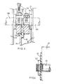
- the illustrated rotary biological contactor (“RBC”) 20 comprises several blocks 22 of plastic media, arranged in the form of a number of rings 24 with five such blocks 22 in each ring 24.
- the blocks 22 are mounted to, or supported on, a framework 26 which supported on a horizontal rotary shaft 28, with the rings 24 axially-spaced-apart along the shaft 28 and concentric thereto.
- One end 28a of shaft 28 is adapted to be driven by an electric motor (not shown) either directly or through a gearbox (not shown) to rotate the RBC 20.
- Fluid to be treated flows generally axially of the RBC so that one end is upstream and the other end is downstream.
- Each block 22 of plastic media is in the form of a stack of sheets 30, 32 (or 30, 32, 34) of plastic media. Adjacent pairs 30, 32 or 32, 34 or 30, 34 of these sheets of plastic media define, between them, part-annular channels 36 which are substantially concentric to the axis of the shaft 28, and substantially concentric to each other, and which intercommunicate radially with each other, as will be described later. These channels 36 are for the through-flow of fluid to be biologically treated in use, when the RBC 20 is rotated.
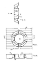
- the stack of plastic sheets 30, 32 (or 30, 32, 34) in each block 22 are placed between two "kite-shaped" hexagonal end support plates 37.
- the sheets 30, 32 (or 30, 32, 34) together with the end support plates 37 are held together by two through-members 38, 40, each in the form of a plastic tube fitted with two end collars 42, 42.
- the support plates 37 aid the assembly of the sheets 30, 32 (or 30, 32, 34) to the plastic through-members 38, 40.
- a sealant and/or adhesive bond is provided between a number of sheets, for example six, at each axial end of the stack, to avoid excessive movement and/or vibration, which might lead to fatigue problems, of those end sheets.
- end collars 42, 42 which are of plastic welded on the plastic tubes 38, 40, serve as end-stops whereby the sheets 30, 32 (or 30, 32, 34) are held together in the stack.
- the tubes 38, 40 with collars 42 are not connected to the framework 26, except via the sheets 30, 32 (or 30, 32, 34) of plastic media.
- the tubes 38, 40 are located substantially on a radial centre plane of the block 22, the tube 38 being a radially-inner through-member and the tube 40 being a radially-outer through-member.
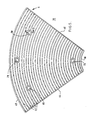
- Each sheet 30, 32, 34 of plastic media is generally in the form of a sector of a circle, each sheet 30, 32, 34 having two radial edges 44, 46, an outer peripheral edge 48 and an inner peripheral edge 50.
- Each sheet 30, 32, 34 is concentric to, and normal to, the axis of the shaft 28.
- sheets 30, 32, 34 are corrugated in either one pattern (sheets 30, Figs. 5 to 8) or another slightly different pattern (sheets 32, Figs. 9 to 12) but a few of the sheets are flat (sheets 34, not separately illustrated). All of the sheets 30, 32, 34 have the same outside dimensions.
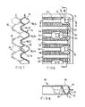
- Each pattern of sheets 30, 32 comprises concentric, part-annular, ribs 56 (as viewed on one face of the sheet 30, 32) alternating with concentric part-annular grooves 58.
- the sheets 30 alternate with the sheets 32 in the stack and all face the same way. That is, all the ribs 56 face the same way.
- the ribs 56 are omitted from Figs. 5 and 9 but are shown in Figs. 6-8 and 10-12 and 14.
- the protruberances 52, 54 which are mentioned above are protruberances from the bottoms of the grooves 58 and protrude in the same direction as the ribs 56.
- the pattern of the protruberances 52 of sheets 30 (Figs. 5 to 8) is different from the pattern of the protruberances 54 of sheets 32, however, so that the protruberances 52 are all in staggered positional relationship to the protruberances 54 as seen in axial elevation, that is, comparing Figs. 5 and 9.
- the protruberances 52 of sheets 30 contact the bases of the grooves 58 of sheets 32 and the protruberances 54 of sheets 32 contact the bases of grooves 58 of sheets 30, thereby spacing the sheets 30, 32 axially apart and providing mutual support.
- This contact is direct or, through intervening biomass, not shown, indirect.
- the stacking of the sheets 30 and 32 alternately with each other thus defines the concentric part-annular channels 36, intercommunicating radially with each other.
- the protruberances 52, 54 partially (but not completely) block the channels 36, so as to deflect fluid radially inwardly and/or radially outwardly from channel to channel, so that the fluid is subjected to a great deal of shear and is brought into maximum surface-to-surface contact with the biomass (not shown) and air, as the RBC 20 rotates in use.
- flanks 60 of the ribs 56 and grooves 58 are corrugated as shown, in order simultaneously to enhance the strength, and to increase the surface area, of each sheet 30, 32. However, they extend over the whole of each flank, preferably. Thus the corrugations extend over all the ribs 56 and grooves 58 except the crests 62 of ribs 56 and the bases 64 of grooves 58.
- Each protruberance 52, 54 has four flanks, namely, radially inner and outer flanks 66, 68 and side flanks 70, 72 and a substantially flat crest 74.
- the crest 74 of each protruberance 52, 54 is level with the crests 62 of ribs 56. It is the crest 74 of each protruberance 52, 54, which engages the base of the groove 58 of the next adjacent sheet 32, 30 (see above).
- Each sheet 30, 32, 34 is formed with two holes 76, 78 on a central radius for the through-members 38, 40 respectively to extend through.
- hole 76 is a radially-inner hole
- hole 78 is a radially-outer hole.
- Each sheet 30, 32, 34 is also formed with two holes 80, 80 for mounting purposes as described below.
- the holes 80, 80 are symmetrically spaced on either side of the central radius at the same radial distance as each other, but on different radiuses.
- the edges of the holes 76, 78, 80, 80 all have flanges 84 reinforced with webbing.
- the sheets 30 alternate with sheets 32 in the blocks 22.
- the crests 74 of the protruberances 52, 54 engage the bases 64 of the grooves 58.
- Interspersed between selected pairs of adjacent sheets 30, 32 (or 32, 30) may be occasional flat sheets 34, in which case the crests 62 of ribs 58 and crests 74 of protruberance 52, 54 engage (directly or, through biomass, indirectly) on the flat sheets 34.
- a flat sheet 34 may obviously be placed between a pair of identically-patterned sheets 30, 30 or 32, 32.
- the holes 76, 78 line up together to receive the through-members 38, 40. Similarly the hole 80, 80 line up.
- the blocks 22 need not all have sheets 30, 32 of the same depths of grooves 58 (and corresponding heights of ribs 56). Although it is preferred for all sheets 30, 32 in a given block 22 to have uniform and identical groove depth (and rib height), a so-called “coarse-hatch” block 22 may have greater groove depth (and rib height) in each sheet 30, 32 than so-called “fine-hatch” block 22. Coarse-hatch blocks 22 are used in the one or two rings 24 at the upstream end and fine-hatch blocks 22 in the remaining rings 24. The coarse-hatch blocks 22 carry more biomass than the fine-hatch blocks.
- the framework 26 is of metal and comprises a respective pair of axially-spaced-apart frames 90 for each ring 24 of blocks 22, located between the pair of frames 90.
- Each frame 90, except the two end frames 90, is located between, and is common to, two adjacent rings 24 of blocks 22.
- Each frame 90 comprises five interconnected sub-frames 92.
- Each sub-frame 92 corresponds to, and supports, a respective one of the five blocks 22 in the or each associated ring 24.
- Each sub-frame 92 comprises a pair of radial arms 94, 94 and outer and inner interconnecting members 96, 98 welded together in the general form of a trapezium.
- the radial arms 94 are secured as by bolts at 98 to annular flanges 100 on the shaft 28, there being one respective annular flange 100 for each respective frame 90.
- the framework 26 also comprises a respective pair of tubular metal support members 102, 102 for each and every block 22 of plastic media.
- the pairs of support members 102, 102 extend parallel to the axis of shaft 28 through the holes 80, 80 of the sheets 30, 32 (or 30, 32, 34) in the stack, at the same radial distance as each other from the shaft axis.
- the metal support members 102, 102 are connected by brackets 104 (Figs. 1 and 3) at their opposite ends to the outer interconnecting members 96 of the two axially-aligned sub-frame 92, between which each plastic media block 22 is mounted respectively.
- the brackets 104 each comprise a seating 106 welded to the interconnecting member 96, a clamping bar 108, two bolts 110 and two corresponding spring washers 112.
- the end of the respective support member 102 is clamped between the seating 106 and the clamping bar 108, which is secured by the two bolts 110, 110 fitted with the washers 112, 112, projecting through two holes in clamping bar 108 into tapped holes in seating 106.
- the support plates 37 in the blocks 22 of plastic media provide some structural support between the plastic through-members 38, 40 and the metal support members 102, 102.
- the RBC 20 is rotated by the motor (not shown) with the horizontal shaft 28 just above the level of the fluid being treated.
- each block 22 of sheets 24 is alternatively dipped into the fluid and lifted into the air.
- the fluid thus flows through the channels 36, being deflected radially inwardly and/or outwardly from channel to channel by the protruberances 52, 54.
- the fluid is subjected to shear and made turbulent, producing good surface-to-surface contact with the air and with the biomass which grows on the plastic media.
- the biomass also has good surface contact alternately with the fluid and with the air.
- the fluid is biologically treated by the rotating RBC 20.
Landscapes
- Life Sciences & Earth Sciences (AREA)
- Water Supply & Treatment (AREA)
- Environmental & Geological Engineering (AREA)
- Biodiversity & Conservation Biology (AREA)
- Microbiology (AREA)
- Chemical & Material Sciences (AREA)
- Engineering & Computer Science (AREA)
- Molecular Biology (AREA)
- Health & Medical Sciences (AREA)
- Hydrology & Water Resources (AREA)
- Organic Chemistry (AREA)
- Biological Treatment Of Waste Water (AREA)
- Toys (AREA)
- Medicines Containing Material From Animals Or Micro-Organisms (AREA)
- Massaging Devices (AREA)
- Switches With Compound Operations (AREA)
- Coupling Device And Connection With Printed Circuit (AREA)
Priority Applications (1)
| Application Number | Priority Date | Filing Date | Title |
|---|---|---|---|
| AT89311084T ATE87598T1 (de) | 1988-10-27 | 1989-10-27 | Rotierfaehiger biologischer tauchtropfkoerper. |
Applications Claiming Priority (2)
| Application Number | Priority Date | Filing Date | Title |
|---|---|---|---|
| GB8825134 | 1988-10-27 | ||
| GB8825134A GB2224275B (en) | 1988-10-27 | 1988-10-27 | Rotary biological contactor |
Publications (2)
| Publication Number | Publication Date |
|---|---|
| EP0366477A1 true EP0366477A1 (fr) | 1990-05-02 |
| EP0366477B1 EP0366477B1 (fr) | 1993-03-31 |
Family
ID=10645865
Family Applications (1)
| Application Number | Title | Priority Date | Filing Date |
|---|---|---|---|
| EP19890311084 Expired - Lifetime EP0366477B1 (fr) | 1988-10-27 | 1989-10-27 | Contacteur biologique rotatif |
Country Status (5)
| Country | Link |
|---|---|
| EP (1) | EP0366477B1 (fr) |
| AT (1) | ATE87598T1 (fr) |
| DE (1) | DE68905751T2 (fr) |
| ES (1) | ES2040470T3 (fr) |
| GB (1) | GB2224275B (fr) |
Cited By (3)
| Publication number | Priority date | Publication date | Assignee | Title |
|---|---|---|---|---|
| EP2113489A1 (fr) * | 2008-04-28 | 2009-11-04 | Dytras, S.A. | Dispositif rotatif d'aération et support de film biologique pour dépuration des eaux usées |
| WO2013103289A1 (fr) | 2012-01-03 | 2013-07-11 | Valdes Simancas Farncisco Xavier | Contacteur biologique rotatif haute capacité |
| US9133042B2 (en) | 2010-12-16 | 2015-09-15 | Biomass Technologies, Llc | Rotating biological contactor apparatus and method |
Families Citing this family (4)
| Publication number | Priority date | Publication date | Assignee | Title |
|---|---|---|---|---|
| US5425874A (en) * | 1994-06-09 | 1995-06-20 | Envirex Inc. | Rotating contactor including cross flow media for the biological treatment of waste water |
| ES2346388B1 (es) * | 2008-10-13 | 2011-09-16 | Cotragua, S.L | Dispositivo de biodiscos para un reactor de depuracion de aguas residuales. |
| US10697294B2 (en) | 2018-02-17 | 2020-06-30 | Datacloud International, Inc | Vibration while drilling data processing methods |
| CN112723507A (zh) * | 2020-12-22 | 2021-04-30 | 湖南省园林建设有限公司 | 一种用于分层式矿山深坑酸性废水处理的重金属捕捉剂及工艺 |
Citations (5)
| Publication number | Priority date | Publication date | Assignee | Title |
|---|---|---|---|---|
| US4345997A (en) * | 1981-03-09 | 1982-08-24 | Crane Co. | Media |
| US4385987A (en) * | 1979-09-11 | 1983-05-31 | Geo. A. Hormel & Company | Water treatment apparatus |
| US4444658A (en) * | 1981-08-10 | 1984-04-24 | Crane Co. | Rotating biological contactor apparatus |
| US4537678A (en) * | 1984-10-04 | 1985-08-27 | Walker Process Corporation | Rotary biological contactor |
| EP0185542A2 (fr) * | 1984-12-18 | 1986-06-25 | Klargester Environmental Engineering Limited | Contacteurs biologiques rotatifs |
Family Cites Families (2)
| Publication number | Priority date | Publication date | Assignee | Title |
|---|---|---|---|---|
| US3904525A (en) * | 1973-08-23 | 1975-09-09 | Lawrence R Rosenberg | Waste treatment apparatus |
| DE3140372C2 (de) * | 1981-10-10 | 1985-06-27 | Stähler, Theo, Dipl.-Landw., 6253 Hadamar | Vorrichtung für die aerobe biologische Reinigung von Abwässern |
-
1988
- 1988-10-27 GB GB8825134A patent/GB2224275B/en not_active Expired - Fee Related
-
1989
- 1989-10-27 AT AT89311084T patent/ATE87598T1/de active
- 1989-10-27 ES ES89311084T patent/ES2040470T3/es not_active Expired - Lifetime
- 1989-10-27 EP EP19890311084 patent/EP0366477B1/fr not_active Expired - Lifetime
- 1989-10-27 DE DE1989605751 patent/DE68905751T2/de not_active Expired - Fee Related
Patent Citations (5)
| Publication number | Priority date | Publication date | Assignee | Title |
|---|---|---|---|---|
| US4385987A (en) * | 1979-09-11 | 1983-05-31 | Geo. A. Hormel & Company | Water treatment apparatus |
| US4345997A (en) * | 1981-03-09 | 1982-08-24 | Crane Co. | Media |
| US4444658A (en) * | 1981-08-10 | 1984-04-24 | Crane Co. | Rotating biological contactor apparatus |
| US4537678A (en) * | 1984-10-04 | 1985-08-27 | Walker Process Corporation | Rotary biological contactor |
| EP0185542A2 (fr) * | 1984-12-18 | 1986-06-25 | Klargester Environmental Engineering Limited | Contacteurs biologiques rotatifs |
Cited By (4)
| Publication number | Priority date | Publication date | Assignee | Title |
|---|---|---|---|---|
| EP2113489A1 (fr) * | 2008-04-28 | 2009-11-04 | Dytras, S.A. | Dispositif rotatif d'aération et support de film biologique pour dépuration des eaux usées |
| US9133042B2 (en) | 2010-12-16 | 2015-09-15 | Biomass Technologies, Llc | Rotating biological contactor apparatus and method |
| WO2013103289A1 (fr) | 2012-01-03 | 2013-07-11 | Valdes Simancas Farncisco Xavier | Contacteur biologique rotatif haute capacité |
| US9969634B2 (en) | 2012-01-03 | 2018-05-15 | Francisco Xavier Valdes Simancas | High-capacity biological contact rotor |
Also Published As
| Publication number | Publication date |
|---|---|
| EP0366477B1 (fr) | 1993-03-31 |
| DE68905751T2 (de) | 1993-08-26 |
| GB8825134D0 (en) | 1988-11-30 |
| ES2040470T3 (es) | 1993-10-16 |
| ATE87598T1 (de) | 1993-04-15 |
| GB2224275B (en) | 1992-08-26 |
| GB2224275A (en) | 1990-05-02 |
| DE68905751D1 (de) | 1993-05-06 |
Similar Documents
| Publication | Publication Date | Title |
|---|---|---|
| KR950031163A (ko) | 필터용 허브링(hub ring) 및 지지판과 이들 부재의 제조방법 | |
| CN1356925A (zh) | 叠层式静态混合器元件 | |
| US7013963B2 (en) | Round plate heat exchanger with improved heat exchange properties | |
| DE2657306C3 (de) | Drehschwingungsdämpfer für die Reibscheiben einer Überbrückungskupplung | |
| EP0366477B1 (fr) | Contacteur biologique rotatif | |
| FI78520C (fi) | Sikt foer renings- eller separeringsanordningar samt foerfarande foer framstaellning av en dylik sikt. | |
| US3827559A (en) | Extended surface rotating biological contactor | |
| US20050013515A1 (en) | Foil bearing | |
| KR960022956A (ko) | 액화된 고형물의 스트립핑 방법 및 장치와 유체 크랙킹 방법에서의 그 용도 | |
| US5425874A (en) | Rotating contactor including cross flow media for the biological treatment of waste water | |
| CA2493144A1 (fr) | Tambour multi-elements pouvant etre remonte sur place pour transporter le cable installe | |
| CA1259717A (fr) | Rotor biologique de traitement des produits d'egout | |
| US5355945A (en) | Heat exchanger and method of fabrication | |
| US3827825A (en) | Axial flow fan assembly | |
| EP0055426A1 (fr) | Structure d'une cellule d'une pompe multicellulaire | |
| CA2373417C (fr) | Element rotatif pour appareil de traitement de l'air | |
| RU2295662C2 (ru) | Вязкостный демпфер крутильных колебаний с охлаждающими каналами | |
| CN113432457B (zh) | 一种用于列管式汽化器的新型换热器结构 | |
| KR20230061220A (ko) | 연도내부 풍속을 이용한 풍력발전장치 | |
| JP2022537897A (ja) | 循環流体間の接触を促進するためにチャンバの内部に配置されるライニング | |
| CN1123377C (zh) | 一种塔或管内构件立交盘 | |
| RU2118196C1 (ru) | Вакуумная насадочная секционированная колонна | |
| JP3831482B2 (ja) | フィルター用支持板またはスペーサの製造方法 | |
| CN212283582U (zh) | 一种陶瓷膜组件及陶瓷膜系统 | |
| KR810000370B1 (ko) | 폐수처리용 회전식 미생물 접촉기 |
Legal Events
| Date | Code | Title | Description |
|---|---|---|---|
| PUAI | Public reference made under article 153(3) epc to a published international application that has entered the european phase |
Free format text: ORIGINAL CODE: 0009012 |
|
| AK | Designated contracting states |
Kind code of ref document: A1 Designated state(s): AT BE CH DE ES FR GB GR IT LI LU NL SE |
|
| 17P | Request for examination filed |
Effective date: 19900828 |
|
| 17Q | First examination report despatched |
Effective date: 19911212 |
|
| RAP1 | Party data changed (applicant data changed or rights of an application transferred) |
Owner name: BLUE CIRCLE INDUSTRIES PLC |
|
| RBV | Designated contracting states (corrected) |
Designated state(s): AT BE CH DE ES FR GR IT LI LU NL SE |
|
| GRAA | (expected) grant |
Free format text: ORIGINAL CODE: 0009210 |
|
| RAP1 | Party data changed (applicant data changed or rights of an application transferred) |
Owner name: ENERGY AND WASTE SYSTEMS LIMITED |
|
| AK | Designated contracting states |
Kind code of ref document: B1 Designated state(s): AT BE CH DE ES FR GR IT LI LU NL SE |
|
| PG25 | Lapsed in a contracting state [announced via postgrant information from national office to epo] |
Ref country code: SE Effective date: 19930331 Ref country code: NL Effective date: 19930331 Ref country code: LI Effective date: 19930331 Ref country code: GR Free format text: LAPSE BECAUSE OF FAILURE TO SUBMIT A TRANSLATION OF THE DESCRIPTION OR TO PAY THE FEE WITHIN THE PRESCRIBED TIME-LIMIT Effective date: 19930331 Ref country code: CH Effective date: 19930331 Ref country code: BE Effective date: 19930331 Ref country code: AT Effective date: 19930331 |
|
| REF | Corresponds to: |
Ref document number: 87598 Country of ref document: AT Date of ref document: 19930415 Kind code of ref document: T |
|
| ITF | It: translation for a ep patent filed |
Owner name: BUGNION S.P.A. |
|
| REF | Corresponds to: |
Ref document number: 68905751 Country of ref document: DE Date of ref document: 19930506 |
|
| ET | Fr: translation filed | ||
| REG | Reference to a national code |
Ref country code: CH Ref legal event code: PL |
|
| NLV1 | Nl: lapsed or annulled due to failure to fulfill the requirements of art. 29p and 29m of the patents act | ||
| REG | Reference to a national code |
Ref country code: ES Ref legal event code: FG2A Ref document number: 2040470 Country of ref document: ES Kind code of ref document: T3 |
|
| PG25 | Lapsed in a contracting state [announced via postgrant information from national office to epo] |
Ref country code: LU Free format text: LAPSE BECAUSE OF NON-PAYMENT OF DUE FEES Effective date: 19931031 |
|
| PLBE | No opposition filed within time limit |
Free format text: ORIGINAL CODE: 0009261 |
|
| STAA | Information on the status of an ep patent application or granted ep patent |
Free format text: STATUS: NO OPPOSITION FILED WITHIN TIME LIMIT |
|
| 26N | No opposition filed | ||
| PGFP | Annual fee paid to national office [announced via postgrant information from national office to epo] |
Ref country code: ES Payment date: 19961031 Year of fee payment: 8 |
|
| PGFP | Annual fee paid to national office [announced via postgrant information from national office to epo] |
Ref country code: FR Payment date: 19961104 Year of fee payment: 8 |
|
| PGFP | Annual fee paid to national office [announced via postgrant information from national office to epo] |
Ref country code: DE Payment date: 19961108 Year of fee payment: 8 |
|
| PG25 | Lapsed in a contracting state [announced via postgrant information from national office to epo] |
Ref country code: ES Free format text: LAPSE BECAUSE OF THE APPLICANT RENOUNCES Effective date: 19971028 |
|
| PG25 | Lapsed in a contracting state [announced via postgrant information from national office to epo] |
Ref country code: FR Free format text: THE PATENT HAS BEEN ANNULLED BY A DECISION OF A NATIONAL AUTHORITY Effective date: 19971031 |
|
| PG25 | Lapsed in a contracting state [announced via postgrant information from national office to epo] |
Ref country code: DE Free format text: LAPSE BECAUSE OF NON-PAYMENT OF DUE FEES Effective date: 19980701 |
|
| REG | Reference to a national code |
Ref country code: FR Ref legal event code: ST |
|
| REG | Reference to a national code |
Ref country code: ES Ref legal event code: FD2A Effective date: 20001102 |
|
| PG25 | Lapsed in a contracting state [announced via postgrant information from national office to epo] |
Ref country code: IT Free format text: LAPSE BECAUSE OF NON-PAYMENT OF DUE FEES;WARNING: LAPSES OF ITALIAN PATENTS WITH EFFECTIVE DATE BEFORE 2007 MAY HAVE OCCURRED AT ANY TIME BEFORE 2007. THE CORRECT EFFECTIVE DATE MAY BE DIFFERENT FROM THE ONE RECORDED. Effective date: 20051027 |