EP0366431A1 - Getränke-Abgabevorrichtung - Google Patents
Getränke-Abgabevorrichtung Download PDFInfo
- Publication number
- EP0366431A1 EP0366431A1 EP89310977A EP89310977A EP0366431A1 EP 0366431 A1 EP0366431 A1 EP 0366431A1 EP 89310977 A EP89310977 A EP 89310977A EP 89310977 A EP89310977 A EP 89310977A EP 0366431 A1 EP0366431 A1 EP 0366431A1
- Authority
- EP
- European Patent Office
- Prior art keywords
- valve
- concentrate
- syrup
- water
- chambers
- Prior art date
- Legal status (The legal status is an assumption and is not a legal conclusion. Google has not performed a legal analysis and makes no representation as to the accuracy of the status listed.)
- Withdrawn
Links
Images


Classifications
-
- B—PERFORMING OPERATIONS; TRANSPORTING
- B67—OPENING, CLOSING OR CLEANING BOTTLES, JARS OR SIMILAR CONTAINERS; LIQUID HANDLING
- B67D—DISPENSING, DELIVERING OR TRANSFERRING LIQUIDS, NOT OTHERWISE PROVIDED FOR
- B67D7/00—Apparatus or devices for transferring liquids from bulk storage containers or reservoirs into vehicles or into portable containers, e.g. for retail sale purposes
- B67D7/06—Details or accessories
-
- B—PERFORMING OPERATIONS; TRANSPORTING
- B67—OPENING, CLOSING OR CLEANING BOTTLES, JARS OR SIMILAR CONTAINERS; LIQUID HANDLING
- B67D—DISPENSING, DELIVERING OR TRANSFERRING LIQUIDS, NOT OTHERWISE PROVIDED FOR
- B67D1/00—Apparatus or devices for dispensing beverages on draught
- B67D1/0042—Details of specific parts of the dispensers
- B67D1/0043—Mixing devices for liquids
- B67D1/0044—Mixing devices for liquids for mixing inside the dispensing nozzle
- B67D1/0046—Mixing chambers
- B67D1/0048—Mixing chambers with baffles
-
- B—PERFORMING OPERATIONS; TRANSPORTING
- B67—OPENING, CLOSING OR CLEANING BOTTLES, JARS OR SIMILAR CONTAINERS; LIQUID HANDLING
- B67D—DISPENSING, DELIVERING OR TRANSFERRING LIQUIDS, NOT OTHERWISE PROVIDED FOR
- B67D1/00—Apparatus or devices for dispensing beverages on draught
- B67D1/0042—Details of specific parts of the dispensers
- B67D1/0081—Dispensing valves
- B67D1/0085—Dispensing valves electro-mechanical
-
- B—PERFORMING OPERATIONS; TRANSPORTING
- B67—OPENING, CLOSING OR CLEANING BOTTLES, JARS OR SIMILAR CONTAINERS; LIQUID HANDLING
- B67D—DISPENSING, DELIVERING OR TRANSFERRING LIQUIDS, NOT OTHERWISE PROVIDED FOR
- B67D1/00—Apparatus or devices for dispensing beverages on draught
- B67D1/08—Details
- B67D1/10—Pump mechanism
- B67D1/101—Pump mechanism of the piston-cylinder type
- B67D1/105—Pump mechanism of the piston-cylinder type for two or more components
- B67D1/106—Pump mechanism of the piston-cylinder type for two or more components the piston being driven by a liquid or a gas
- B67D1/107—Pump mechanism of the piston-cylinder type for two or more components the piston being driven by a liquid or a gas by one of the components to be dispensed
-
- B—PERFORMING OPERATIONS; TRANSPORTING
- B67—OPENING, CLOSING OR CLEANING BOTTLES, JARS OR SIMILAR CONTAINERS; LIQUID HANDLING
- B67D—DISPENSING, DELIVERING OR TRANSFERRING LIQUIDS, NOT OTHERWISE PROVIDED FOR
- B67D1/00—Apparatus or devices for dispensing beverages on draught
- B67D1/08—Details
- B67D1/12—Flow or pressure control devices or systems, e.g. valves, gas pressure control, level control in storage containers
- B67D1/1284—Ratio control
- B67D1/1286—Ratio control by mechanical construction
- B67D1/1288—Multi-chamber piston pumps
-
- B—PERFORMING OPERATIONS; TRANSPORTING
- B67—OPENING, CLOSING OR CLEANING BOTTLES, JARS OR SIMILAR CONTAINERS; LIQUID HANDLING
- B67D—DISPENSING, DELIVERING OR TRANSFERRING LIQUIDS, NOT OTHERWISE PROVIDED FOR
- B67D1/00—Apparatus or devices for dispensing beverages on draught
- B67D1/0042—Details of specific parts of the dispensers
- B67D1/0081—Dispensing valves
- B67D2001/0087—Dispensing valves being mounted on the dispenser housing
- B67D2001/0089—Dispensing valves being mounted on the dispenser housing operated by lever means
Definitions
- This invention relates to post-mix beverage dispensers and to dispensing valves for mixing together and dispensing a controlled ratio of syrup and carbonated water; more particularly, this invention concerns a volumetric ratio control device in the dispensing valve.
- a beverage dispensing valve for mixing together a quantity of water and concentrate in a predetermined and controlled ratio, and for dispensing the mixture therefrom comprising:
- the volumetric ratio control device includes syrup and soda pistons connected together, associated syrup and soda chambers, and valves for controlling the flow to and from the chambers.
- the VRCD provides an improvement over known dispensing valves because it does not require high flowing pressures and because the pistons allow one liquid flow to compensate for fluctuations in the other liquid flow.
- the VRCD is simpler and less expensive than the new electrical ratio control valves because it is not concerned with (and does not measure) temperatures, viscosities, syrup characteristics or Reynolds numbers, for example.
- the VRCD is only concerned with repeatedly filling volumetric measuring chambers and then emptying the chambers into a mixing nozzle.
- VRCD can work with a variety of different post-mix syrup packages.
- Present pressurized post-mix dispensers require a source of pressurized syrup to operate correctly. This syrup can come from a pressurized figal or from a syrup pump that is connected to a bag-in-box package.
- the VRCD of this invention overcomes this shortcoming because it can work as a pressurized valve or as a valve/pump combination. When operated as a pressure valve, it can function properly with high pressure syrup or with low pressure syrup.
- the VRCD When operated as a valve/pump combination, it can empty the contents of a bag-in-box package, a vented package, or a very low pressure syrup package, without the use of a syrup pump.
- the VRCD also works with a gravity dispenser and will provide better ratio control than the gravity dispenser valves presently being used. To summarize, the VRCD will work with either a gravity dispenser or a pressurized dispenser. It will work with pressurized containers (figals) or non-pressurized containers (bag-in-box, syrup containers, etc.). Because the VRCD in this invention works with syrups at no pressure and at low pressures, the present invention also includes inexpensive, non-returnable, syrup containers including one that can operate at no pressure and ones that can be pressurized up to about 5 to 10 psig.
- VRCD of this invention can work with all of these different types of dispensers and syrup packages, and it can do so without making any adjustments to the dispensing valve, and without adding any auxiliary equipment (such as a syrup pump) to the valve or dispenser.
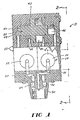
- Figs. 1 - 5 show a dispensing valve 10 according to one embodiment of the present invention.
- the dispensing valve 10 can be mounted on a beverage dispenser 12 as shown in Fig. 14. Any one of a number of the dispensing valves 10 such as four, five or six, for example, can be mounted on the beverage dispenser 12.
- the syrup source can be a figal 14, a bag-in-box 16, a gravity tank 18 built directly into the beverage dispenser 12, or a non-returnable container 20 described in more detail hereinafter.
- the valve includes a body 22 including separate soda and syrup passageways 24 and 26, respectively, therethrough, valve means 28 for controlling the flow through the passageways 24 and 26, a nozzle 30 for mixing together the soda and syrup and for dispensing the mixture therefrom, and a volumetric ratio control device (VRCD) 32 in said body for controlling the ratio of soda to syrup in the beverage dispensed from the valve 10.
- the valve 10 can include a cover 9 (see Fig. 14), if desired.
- the VRCD 32 includes a syrup piston 40, a soda piston 42 connected to the syrup piston 40, a pair of syrup chambers 44 and 46, a pair of soda chambers 48 and 50, two four-way valves 52 and 54, and two solenoids 56 and 58.
- the soda passageway 24 includes a passageway to each of the soda chambers 48 and 50
- the syrup passageway 26 includes a syrup passageway to each of the syrup chambers 44 and 46.
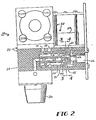
- the valve means for controlling the flow through the passageways includes the solenoids 56 and 58, one of which (58) is shown in Fig. 2 controlling an armature 60 in the syrup passageway 26.
- the armature When the armature is in the position shown in Fig. 2 (for example, with the solenoid 58 not energized), the syrup can flow through syrup inlet passageway 26, through a port 62 in the armature 60, through passageways 70 and 71, one of the syrup chambers 44 or 46, while at the same time syrup is flowing from the other of the chambers 44 or 46 through the passageway 64, then through the groove 66, and then into passageway 68 where it flows down into the nozzle 30 as shown in Fig. 2.
- the solenoid 58 When the syrup piston 40 reaches the end of its stroke, the solenoid 58 is energized to retract the armature 60 to provide communication between the inlet passageway 26 and the other syrup chamber through the passageways 64 and 65, while syrup is forced out of the other syrup chamber into the nozzle through passageway 71, then passageway 70, through groove 66 and then through passageway 68 to the nozzle 30.
- the same operation occurs on the other side of the dispensing valve with respect to the soda (or carbonated water).
- Fig. 3 shows the three ports 72, 73 and 74 providing communication with the passageways 70, 68 and 64, respectively, in a central member 76.
- Fig. 4 shows the port 62 and the groove 68 in the armature 60 of the solenoid 58.
- the solenoids 56 and 58 and the valves 52 and 54 direct syrup and soda to the left side of the pistons as shown in Fig. 5, while the pistons move from left to right causing the liquids on the right side of the pistons to be expelled into the mixing nozzle.
- the solenoids are energized to activate the valves and thus reverse the flow and cause the liquids on the left side of the pistons to be directed to the mixing nozzle.
- the pistons will preferably change directions several times each second. In order to change ratio in this type of valve, the pistons/chamber assembly must be replaced with a different sized assembly.
- An advantage of placing the VRCD directly in the dispensing valve is to reduce the number of water lines that would be required if the VRCD were placed, for example, upstream of the refrigeration system and the soda and syrup lines were kept separate up to the valve.
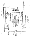
- FIG. 6 and 7 show another embodiment of the VRCD of the present invention, and in particular one using four three-way valves rather than the two four-way valves used in the embodiments of Figs. 1-5.
- Figs. 6 and 7 show a volumetric ratio control device 80 that can be used in a dispensing valve such as the valve 10 of Figs. 1-5.
- Figs. 6 and 7 diagrammatically show the syrup piston 40, the soda piston 42, syrup chambers 44 and 46, and the soda chambers 48 and 50.
- the volumetric ratio control device 80 includes a soda-in conduit 82, a syrup-in conduit 84, a soda-out conduit 86 to a mixing nozzle 88, and a syrup-out conduit 90 to the mixing nozzle 88.
- the volumetric ratio control device 80 includes valve means for controlling the flow in the soda and syrup passageways including four three-way pilot-actuated poppet valves 92, 94, 96 and 98 controlled by a single solenoid-actuated pilot valve 100.
- the valve 100 is actuated by a solenoid 102.
- the solenoid-actuated pilot valve 100 uses pressurized soda as the pilot fluid.
- Fig. 6 shows the solenoid 102 in its energized condition such that the valve 100 is open to provide pressurized soda communication to the four three-way poppet valves 92, 94, 96 and 98 to position these valves in their orientation shown in Fig. 6 with the pistons 40 and 42 moving to the left as shown in Fig. 6.
- the solenoid 102 is de-energized allowing a spring to move the pilot valve to its position shown in Fig. 7.
- the soda line to the four three-way poppet valves is vented by the pilot valve 100 which causes the four three-way valves 92, 94, 96 and 98 to move to their position shown in Fig.
- Figs. 8 to 10 show a dispensing valve 110 according to another embodiment of the present invention which uses four three-way paddle valves 111, 112, 113 and 114 which are mechanically actuated by a single solenoid 116 having an armature 117.
- the valves 111 and 113 are syrup valves, and valves 112 and 114 are soda valves.
- the cross-section in Fig. 8 is taken through the syrup valves 111 and 113.
- the cross-section in Fig. 9 is taken through the valves 113 and 114.
- the dispensing valve 110 includes the syrup piston 40, the soda piston 42, syrup chambers 44 and 46, soda chambers 48 and 50, and the nozzle 30.
- the dispensing valve 110 includes a body 118 having a syrup passageway 120 and a soda passageway 122 therethrough.
- the solenoid 116 includes a spring (not shown) for forcing the armature 117 downwardly (as viewed in Fig. 8). When the solenoid is energized it pulls the armature 117 upwardly.
- Fig. 8 shows the pistons 40 and 42 moving to the left, the paddle valves 113 and 114 being opened by the solenoid 116 being energized to pull upon a lever arm 126 (as viewed in Fig.
- the paddle valves 111 and 112 are caused to close.
- the soda and syrup flows through the soda and syrup passageways into the rightmost chambers 50 and 46 filling those chambers, and the soda and syrup is at the same time forced out of the leftmost chambers to the nozzle 30.
- the solenoid 116 is de-energized, whereby the solenoid spring (not shown) forces the lever arm 126 down, reversing the above described liquid flow.
- Fig. 11 is a diagrammatic and schematic showing of a syrup piston 140, a soda piston 142, syrup chambers 144 and 145, and soda chambers 146 and 147.
- Fig. 11 also shows electrical circuit contact means 148 for detecting when the pistons 140 and 142 have reached the end of their stroke.
- the electrical contact means 148 can use microswitches 149 and 150 for energizing the solenoid means of the various valve means shown in the drawings of the previously described embodiments.
- Fig. 12 shows a variable flow rate system that can be used on any of the embodiments described herein.
- This system includes a cup lever arm 151 located below a dispensing valve 10 and adjacent to the nozzle 30 as is well-known in the art for actuating a dispensing valve to dispense the beverage into a cup.
- cup lever arm 151 moves immediately energizes a switch 152 to actuate the dispensing valve. This switch remains closed as long as the arm 151 is depressed.
- the cup lever arm 151 is also connected to a flow control 154 (through an arm 153) in the soda passageway 156 to the nozzle 30. If a high flow rate is desired, the cup lever arm 151 is pushed all the way back, whereby the flow control 154 provides a completely open passageway 156.
- the cup lever arm 151 is spring biased to its closed position shown in Fig. 12 and can be moved varying amounts to the right (as viewed in Fig. 12) to dispense beverage into a cup and to open the soda passageway 156 in varying amounts.
- the cup lever arm 151 is allowed to move toward its closed position whereby the flow control 154 moves into the passageway 156 to slow down the flow.
- the volumetric ratio control device even though only one of the soda and/or syrup passageways to the nozzle is varied, the ratio remains constant, because when the piston slows down, it slows down the pumping of both the soda and the syrup and at the correct ratio.
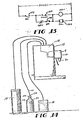
- Fig. 13 shows a standard electrical circuit, including a holding circuit, for causing the soda and syrup pistons to reciprocate when the dispensing valve including the VRCD is energized.
- Fig. 13 shows the switches 152, 149 and 150, the solenoid 102 and relay CR-1. The operation of this standard circuit is well known and need not be described in any further detail herein.
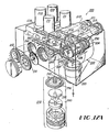
- Fig. 14 shows an overall arrangement of a beverage dispenser 12 with one or more dispensing valves 10 according to any one of the embodiments of the present invention.
- the beverage dispenser 12 can be provided with a syrup supply from any one of a known type of syrup containers such as a figal 14, a bag-in-box 16, or a gravity tank 18.
- a syrup supply can also be provided in a non-returnable container 20 such as a plastic bottle.
- the container can be vented to atmosphere or preferably it can be a container that is capable of being safely pressurized to no higher than about 10 psig.
- the container 20 can be similar to the present two-liter PET bottles used for premix.
- the container 20 includes a lid 170 having a dip tube 172 extending down toward the bottom of the container 20 and a coupling for connection to the syrup line 21.
- the lid 170 also includes a one-way valve and fitting 174 for use in pressurizing the container 20 to its low pressure. It is noted that the pressure to which container 20 can be pressurized is much less than that to which a stainless steel figal 20 can be pressurized. According to the present arrangement the means for delivering the syrup to the dispensing valve is the suction created by the volumetric ratio control device; however, it can be useful to have a small pressure in the container 20, if desired.
- the low pressure that is preferred to be used in the container 20 does not require the container to withstand any substantial pressures, whereby the container 20 can be made relatively inexpensively; that is, it can have relatively thin walls and a relatively inexpensive lid 170 that can be screw-threaded (or otherwise connected) onto the container 20 with a suitable O-ring or other seal structure.
- the container 14, 16 and 20 are connected in the usual, known, manner to the beverage dispenser 12; this is what is intended by the arrows on the ends of the syrup conduits.
- the dispenser 12 may or may not include a gravity tank 18.
- Figs. 15-25 show a dispensing valve 200 according to a preferred embodiment of the present invention.
- the valve 200 differs from the above-described valves in that it uses check valves to control the flow of syrup to and from the syrup metering piston along with a pressure regulator, and is thus simpler, less expensive and more compact.
- the valve 200 includes a body 202 including separate soda and syrup passageways 204 and 206, respectively, therethrough, solenoid valves 208, 209, 210 and 211 to control the soda flow, check valves 212, 213, 214 and 215 (such as umbrella valves) and a pressure regulator 216 to control the syrup flow, a nozzle 220 for mixing together the soda and syrup and for dispensing the mixture therefrom, and a VRCD 222 in said body 202 for controlling the ratio of soda to syrup in the beverage dispensed from the valve 200.
- the VRCD 222 includes a single metering piston element (which comprises a syrup piston 224 and a soda piston 226), a pair of syrup chambers 228 and 230, and a pair of soda chambers 232 and 234.
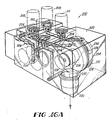
- Figs. 16A and 16B show the soda flow.
- valves 208 and 211 are open and valves 209 and 210 are closed and the soda piston 226 is moving to the right (as viewed in Fig. 16A), thus soda is flowing into chamber 232 and out of chamber 234.
- Soda flows through open valve 208 into chamber 232, and soda flows out chamber 234 through open valve 211 into the nozzle 220.
- valves 209 and 210 are open and valves 208 and 211 are closed and the soda piston 226 is moving to the left. Soda flows through open valve 209 into the chamber 234 and soda flows out chamber 232 through the open valve 210.
- Figs. 17A and 17B show the syrup flow.
- the syrup piston 224 is moving to the right (this Fig. corresponds to Fig. 16A).
- Syrup flows into the top of the pressure regulator 216 and is in communication with the four check valves 212-215.
- Syrup chamber 230 is under pressure and forces syrup through check valve 215, then to the pressure regulator 216 and then to the nozzle 220.
- Syrup chamber 228 is under lower pressure than the inlet syrup pressure and thus syrup flows through the check valve 212 and into chamber 228.
- Fig. 17B shows the syrup flow when the syrup piston is moving to the left. Syrup is under pressure in chamber 228 and flows through check valve 214 and then to the pressure regulator 216 and then to the nozzle. Chamber 230 is under less pressure than the inlet syrup pressure and thus syrup will flow through check valve 213 and into chamber 230.
- Fig. 17C is a schematic drawing showing the syrup passageway 206 (i.e. the syrup circuit) including the four check valves 212-215, the syrup piston 224, the two syrup chambers 228 and 230, and the pressure regulator 216.
- the pressure regulator prevents syrup from flowing directly through the passageway 206 during non-dispensing times, even though the syrup is under pressure and even though the flow is controlled using only check valves.
- the syrup circuit includes passageways 240 and 241 (see Figs. 17 and 21) that communicate between check valves 212 and 213, and the pressure chamber 250 of the pressure regulator, and passageways 242 and 243 that communicate between the outlet side of check valves 212 and 213 and the inlet side of check valves 214 and 215 and the syrup chambers 228 and 230, respectively, of the VRCD 22.
- the syrup circuit includes passageways 244 and 246 that communicate between the outlet side of valves 214 and 215 and the inlet chamber 252 of the pressure regulator 216.
- Each of these passageways 244 and 246 consist of two separate passages of circular cross-section because of space constraints; one larger passageway could be used if room existed for it.
- Syrup passageway 248 feeds syrup from the pressure regulator 216 to the nozzle.
- the pressure regulator 216 prevents "blow-through" of syrup, under pressure of the syrup source, through the check valves, and includes a diaphragm 256 separating the pressure and inlet chambers 250 and 252, respectively.
- a needle valve 258 is biased to its closed position in opening 260 by the pressure of the syrup in the pressure chamber 250 plus the additional force of the biasing spring 262. However, when the piston 226 operates, the pressure of the syrup in the outlet chamber 252 is sufficient to cause the diaphragm to move up and open the needle valve 258 so syrup can flow through the opening 260 and the passageway 248 into the outlet chamber 253 and then through the passageway 248 to the nozzle 220.
- the outlet chamber 253 comprises four drilled holes and an annular groove, but it can alternatively be an open chamber.
- the biasing spring 262 insures that the pressure in the outlet lines from the syrup chambers is greater than that in the inlet lines thereto, no matter what the inlet pressure is. This arrangement prevents blow-through at all pressures. By adjusting the spring force, the pressure differential can be changed, and thus the spring force is preferably made adjustable.
- Figs. 18-24 further show the soda and syrup passageways in the valve 200.
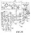
- Fig. 25 is an electric schematic of electric control means 270 for the valve 200 of Figs. 15-24.
- the control means 270 includes an internal power supply 272 which converts 24 VAC readily available from the dispenser to 12 VDC to provide the supply for this circuit.
- This power supply is mounted on the valve body on the same P.C. board 268 as the remainder of the circuit.
- the circuit also includes two Hall effect sensors 264 (the location of which is shown in Fig. 24). These sensors sense the position of the metering piston which is equipped with an internally mounted magnet 280. When the piston approaches the left or right extreme position, one of the sensors generates a control signal.
- the circuit 270 also includes a comparator section 282. If the voltage level received from a sensor equals or exceeds the voltage level applied to the comparator chip, then the comparator sends the signal to the flip flop 284 to switch the solenoids 208-211.
- the reference voltage level applied to either comparator can be varied, thus allowing the switching point (piston travel) to be adjusted.
- the flip-flop 284 (U2A and U2B) is the basic switching element in the circuit. Its state depends on the signals received from both comparators.
- the gates (U2C, U2D) work in conjunction with the switch 286 to turn the switching function on and off.
- the driver chips 288 transmit the signals from the flip flop 284 and raise their power to the level required by the inputs of the opto isolated triacs 290.
- the opto isolated triacs 290 when enabled (switched on) by the light from the input LED (light emitting diode), allow the 24 AC voltage to be applied to the solenoid coils and thus actuate the solenoid plungers by lifting them off the seat.
- the control board operates 4 solenoids, each triac actuating a pair of solenoids connected in parallel.
- valves such as the well-known postmix valves of which 4-6 are commonly arranged side by side on the front of well-known countertop beverage dispensers such as are used in restaurants. These valves have a size of about 3"W x 5"H x 6"D.
- the non-returnable container 20 can alternatively be vented to atmosphere and not be under any additional pressure.
- the preferred water and concentrate are carbonated water and syrup, respectfully, this invention can also be used with plain water and with fruit juice concentrates, tea and coffee, for example.
- the solenoids are preferably pull solenoids, push solenoids can also be used.
- the soda and syrup pistons in the VRCD can be separate pistons joined together, or they can be one single member. Other pressure regulators can be used in place of 222 and other arrangements of soda and syrup circuits then that shown in Figs. 15-24 can be used.
- a dispensing valve for a beverage dispenser that can operate as a valve/pump combination that can empty the contents of a bag-in-box package or a non-returnable, low pressure or no pressure syrup package, without the use of a syrup pump , by incorporating a volumetric ratio control device for dispensing from a non-pressurizable, collapsible concentrate container without the use of a syrup pump.
- the beverage dispensing system includes a beverage dispenser, a dispensing valve, and a non-returnable, rigid, pressurizable syrup container pressurized to about 5-10 psig., or a non-returnable, pressurizable syrup container for use with beverage dispensers and having sufficient strength to safely hold syrup under pressure no greater than about 5-10 psig.
Applications Claiming Priority (2)
| Application Number | Priority Date | Filing Date | Title |
|---|---|---|---|
| US07/261,876 US4966306A (en) | 1986-07-18 | 1988-10-24 | Beverage dispenser system using volumetric ratio control device |
| US261876 | 1999-03-02 |
Publications (1)
| Publication Number | Publication Date |
|---|---|
| EP0366431A1 true EP0366431A1 (de) | 1990-05-02 |
Family
ID=22995260
Family Applications (1)
| Application Number | Title | Priority Date | Filing Date |
|---|---|---|---|
| EP89310977A Withdrawn EP0366431A1 (de) | 1988-10-24 | 1989-10-24 | Getränke-Abgabevorrichtung |
Country Status (8)
| Country | Link |
|---|---|
| US (1) | US4966306A (de) |
| EP (1) | EP0366431A1 (de) |
| JP (1) | JPH02258595A (de) |
| KR (1) | KR900006226A (de) |
| AU (1) | AU4368989A (de) |
| BR (1) | BR8905390A (de) |
| CA (1) | CA2000951A1 (de) |
| ZA (1) | ZA898053B (de) |
Families Citing this family (24)
| Publication number | Priority date | Publication date | Assignee | Title |
|---|---|---|---|---|
| US5181631A (en) * | 1986-07-18 | 1993-01-26 | The Coca-Cola Company | Beverage dispenser valve with controllable flow rate |
| US5121855A (en) * | 1986-07-18 | 1992-06-16 | The Coca-Cola Company | Beverage dispenser system using volumetric ratio control device |
| US5062555A (en) * | 1989-04-03 | 1991-11-05 | The Coca-Cola Company | Microprocessor based ratio adjustment and portion control system for postmix beverage dispensing valves |
| US5172831A (en) * | 1991-12-23 | 1992-12-22 | Ebtech, Inc. | Valve actuator for a soft drink dispenser station |
| US5381926A (en) * | 1992-06-05 | 1995-01-17 | The Coca-Cola Company | Beverage dispensing value and method |
| US5332123A (en) * | 1992-06-22 | 1994-07-26 | The Coca-Cola Company | Device for the measured dispensing of liquids out of a storage container and synchronous mixing with a diluent |
| US5366159A (en) * | 1992-09-14 | 1994-11-22 | Childers Lance L | Automatic lawn and garden feeding apparatus |
| US5425968A (en) * | 1992-12-24 | 1995-06-20 | E. I. Du Pont De Nemours And Company | Method and apparatus for the refinish application of multicomponent coating compositions |
| US5499745A (en) * | 1994-02-18 | 1996-03-19 | Nordson Corporation | Apparatus for mixing and dispensing two chemically reactive materials |
| US5881919A (en) * | 1997-10-28 | 1999-03-16 | The University Of Tennessee Research Corporation | Liquid injection system for sprayers |
| KR100322258B1 (ko) * | 1999-12-03 | 2002-02-06 | 박정훈 | 월풀을 이용한 발안마기능이 구비된 안마의자 |
| US6394773B1 (en) * | 2001-01-19 | 2002-05-28 | The Coca-Cola Company | Pump for concentrate packages |
| JP2004131180A (ja) * | 2002-07-09 | 2004-04-30 | Imi Cornelius (Uk) Ltd | 飲料の注出における改良または飲料の注出に関連する改良 |
| AU2003283633A1 (en) * | 2002-11-26 | 2004-06-18 | Richard Anthony Khalaf | Beverage mixing and dispensing apparatus and pumps for use therein |
| US20050072800A1 (en) * | 2003-09-19 | 2005-04-07 | Smith Clyde M. | Fluid powered proportioning pump and post-mix beverage dispenser system using same |
| US20050123416A1 (en) * | 2003-12-06 | 2005-06-09 | Smith Clyde M. | Combined piston fluid motor and pump |
| IN2012DN01701A (de) * | 2009-07-29 | 2015-06-05 | Graco Minnesota Inc | |
| US20120048307A1 (en) * | 2010-08-25 | 2012-03-01 | Ecolab Usa Inc. | Method and system for dispensing incompatible products |
| NL2008659C2 (en) * | 2012-04-19 | 2013-10-29 | Groeneveld Transp Efficiency B V | Device for dispensing charges of a fluid. |
| US11124406B1 (en) * | 2014-07-13 | 2021-09-21 | Sestra Systems, Inc. | System and method for piston detection in a metering mechanism for use with beverage dispensing system |
| USD795631S1 (en) | 2015-05-01 | 2017-08-29 | The Baby Barista Company | Apparatus for preparing ingredients for a baby bottle |
| WO2016179052A1 (en) | 2015-05-01 | 2016-11-10 | The Baby Barista Company | Apparatus and method for preparing ingredients for a baby bottle using a concentrated solution |
| US11396446B2 (en) * | 2017-05-15 | 2022-07-26 | Gate Cfv Solutions, Inc. | High ratio fluid control |
| LT6744B (lt) * | 2018-09-10 | 2020-07-10 | Uab "Aparata" | Automatinis kavos ir arbatos virimo aparatas |
Citations (3)
| Publication number | Priority date | Publication date | Assignee | Title |
|---|---|---|---|---|
| DE1217232B (de) * | 1964-12-15 | 1966-05-18 | Danfoss As | Vorrichtung zum Abfuellen von Fluessigkeiten |
| EP0253406A2 (de) * | 1986-07-18 | 1988-01-20 | The Coca-Cola Company | Getränkespender mit Volumenverhältnis-Regelvorrichtung |
| EP0266223A1 (de) * | 1986-10-31 | 1988-05-04 | The Coca-Cola Company | Pumpenanlage für einen Getränkespender mit einer Druckhaltevorrichtung |
Family Cites Families (5)
| Publication number | Priority date | Publication date | Assignee | Title |
|---|---|---|---|---|
| US2736466A (en) * | 1950-10-11 | 1956-02-28 | Joseph J Rodth | Liquid metering and dispensing device |
| US4171191A (en) * | 1976-03-25 | 1979-10-16 | Krueger Wallace F | Apparatus for transferring metered quantities of material from one location to another |
| FR2348421A1 (fr) * | 1976-04-14 | 1977-11-10 | Euracom Sa | Robinet perfectionne |
| SU617684A1 (ru) * | 1976-10-08 | 1978-07-30 | Запорожский Филиал Всесоюзного Научно-Исследовательского И Конструкторского Института "Цветметавтоматика" | Дозатор жидкостей |
| US4778353A (en) * | 1980-09-25 | 1988-10-18 | Facet Enterprises, Inc. | Hall switch pump |
-
1988
- 1988-10-24 US US07/261,876 patent/US4966306A/en not_active Expired - Fee Related
-
1989
- 1989-10-18 CA CA002000951A patent/CA2000951A1/en not_active Abandoned
- 1989-10-23 JP JP1273931A patent/JPH02258595A/ja active Pending
- 1989-10-23 BR BR898905390A patent/BR8905390A/pt unknown
- 1989-10-24 ZA ZA898053A patent/ZA898053B/xx unknown
- 1989-10-24 AU AU43689/89A patent/AU4368989A/en not_active Abandoned
- 1989-10-24 KR KR1019890015312A patent/KR900006226A/ko not_active Application Discontinuation
- 1989-10-24 EP EP89310977A patent/EP0366431A1/de not_active Withdrawn
Patent Citations (3)
| Publication number | Priority date | Publication date | Assignee | Title |
|---|---|---|---|---|
| DE1217232B (de) * | 1964-12-15 | 1966-05-18 | Danfoss As | Vorrichtung zum Abfuellen von Fluessigkeiten |
| EP0253406A2 (de) * | 1986-07-18 | 1988-01-20 | The Coca-Cola Company | Getränkespender mit Volumenverhältnis-Regelvorrichtung |
| EP0266223A1 (de) * | 1986-10-31 | 1988-05-04 | The Coca-Cola Company | Pumpenanlage für einen Getränkespender mit einer Druckhaltevorrichtung |
Also Published As
| Publication number | Publication date |
|---|---|
| AU4368989A (en) | 1990-04-26 |
| BR8905390A (pt) | 1990-05-22 |
| JPH02258595A (ja) | 1990-10-19 |
| ZA898053B (en) | 1990-09-26 |
| KR900006226A (ko) | 1990-05-07 |
| CA2000951A1 (en) | 1990-04-24 |
| US4966306A (en) | 1990-10-30 |
Similar Documents
| Publication | Publication Date | Title |
|---|---|---|
| US5181631A (en) | Beverage dispenser valve with controllable flow rate | |
| US4966306A (en) | Beverage dispenser system using volumetric ratio control device | |
| US5121855A (en) | Beverage dispenser system using volumetric ratio control device | |
| EP0532062B1 (de) | Getränkeabgabeeinrichtung mit Kontrollvorrichtung für das Mengenverhältnis | |
| US4953754A (en) | Beverage dispenser system using volumetric ratio control device | |
| US4779761A (en) | Beverage dispenser pump system with pressure control device | |
| US6564971B2 (en) | Beverage dispenser | |
| US5332123A (en) | Device for the measured dispensing of liquids out of a storage container and synchronous mixing with a diluent | |
| US3664550A (en) | Dispensing system for beverages and other liquids | |
| US6712242B2 (en) | Fluid dispensing system and dual-mode, system fluid actuated valve for use therein | |
| WO1999037577A2 (en) | Post-mix dispensing module for concentrates | |
| EP2041396B1 (de) | Flüssigkeitsgetriebene verteilungspumpe und system zur flüssigkeitsausgabe mit einer solchen pumpe | |
| US5088625A (en) | Drive mechanism for the measured dispensing of liquids out of a storage container | |
| US5476193A (en) | Positive displacement, volumetric ratio beverage dispersing apparatus | |
| US5071038A (en) | Beverage dispenser system using volumetric ratio control device | |
| US4736873A (en) | Self powered liquor metering pump | |
| US5060824A (en) | Beverage dispenser system using volumetric ratio control device | |
| US5234134A (en) | Device for the measured dispensing of liquids out of a storage container | |
| US5241988A (en) | Quick opening and closing valve | |
| EP2039650A1 (de) | Ausschankvorrichtung für mehrere Getränke | |
| CA2485390A1 (en) | Fluid dispensing system and dual-mode, system fluid actuated valve for use therein | |
| EP0197655A2 (de) | Vorrichtung zum Wiederherstellen von Konzentraten | |
| CA2032011C (en) | Device for the measured dispensing of liquids out of a storage container and synchronous mixing with a diluent | |
| GB2366335A (en) | Dispense valve | |
| JPS63178990A (ja) | 圧力制御装置を有する飲料分配ポンプシステム |
Legal Events
| Date | Code | Title | Description |
|---|---|---|---|
| PUAI | Public reference made under article 153(3) epc to a published international application that has entered the european phase |
Free format text: ORIGINAL CODE: 0009012 |
|
| AK | Designated contracting states |
Kind code of ref document: A1 Designated state(s): AT BE CH DE ES FR GB GR IT LI LU NL SE |
|
| 17P | Request for examination filed |
Effective date: 19901029 |
|
| 17Q | First examination report despatched |
Effective date: 19920601 |
|
| STAA | Information on the status of an ep patent application or granted ep patent |
Free format text: STATUS: THE APPLICATION IS DEEMED TO BE WITHDRAWN |
|
| 18D | Application deemed to be withdrawn |
Effective date: 19921013 |