EP0366358A2 - Système d'admission pour un moteur à combustion interne à plusieurs cylindres - Google Patents
Système d'admission pour un moteur à combustion interne à plusieurs cylindres Download PDFInfo
- Publication number
- EP0366358A2 EP0366358A2 EP89310756A EP89310756A EP0366358A2 EP 0366358 A2 EP0366358 A2 EP 0366358A2 EP 89310756 A EP89310756 A EP 89310756A EP 89310756 A EP89310756 A EP 89310756A EP 0366358 A2 EP0366358 A2 EP 0366358A2
- Authority
- EP
- European Patent Office
- Prior art keywords
- cylinders
- resonance
- resonance portion
- rows
- cylinder row
- Prior art date
- Legal status (The legal status is an assumption and is not a legal conclusion. Google has not performed a legal analysis and makes no representation as to the accuracy of the status listed.)
- Granted
Links
- 238000002485 combustion reaction Methods 0.000 title claims description 20
- 238000009826 distribution Methods 0.000 abstract description 7
- 230000000694 effects Effects 0.000 abstract description 6
- 238000009434 installation Methods 0.000 description 4
- 238000010586 diagram Methods 0.000 description 2
- 230000001360 synchronised effect Effects 0.000 description 2
- 241001052209 Cylinder Species 0.000 description 1
- 230000003247 decreasing effect Effects 0.000 description 1
- 230000008030 elimination Effects 0.000 description 1
- 238000003379 elimination reaction Methods 0.000 description 1
- 239000000446 fuel Substances 0.000 description 1
- 239000007789 gas Substances 0.000 description 1
- 238000000926 separation method Methods 0.000 description 1
- 238000009827 uniform distribution Methods 0.000 description 1
Images

Classifications
-
- F—MECHANICAL ENGINEERING; LIGHTING; HEATING; WEAPONS; BLASTING
- F02—COMBUSTION ENGINES; HOT-GAS OR COMBUSTION-PRODUCT ENGINE PLANTS
- F02B—INTERNAL-COMBUSTION PISTON ENGINES; COMBUSTION ENGINES IN GENERAL
- F02B27/00—Use of kinetic or wave energy of charge in induction systems, or of combustion residues in exhaust systems, for improving quantity of charge or for increasing removal of combustion residues
- F02B27/005—Oscillating pipes with charging achieved by arrangement, dimensions or shapes of intakes pipes or chambers; Ram air pipes
-
- F—MECHANICAL ENGINEERING; LIGHTING; HEATING; WEAPONS; BLASTING
- F02—COMBUSTION ENGINES; HOT-GAS OR COMBUSTION-PRODUCT ENGINE PLANTS
- F02B—INTERNAL-COMBUSTION PISTON ENGINES; COMBUSTION ENGINES IN GENERAL
- F02B27/00—Use of kinetic or wave energy of charge in induction systems, or of combustion residues in exhaust systems, for improving quantity of charge or for increasing removal of combustion residues
- F02B27/008—Resonance charging
-
- F—MECHANICAL ENGINEERING; LIGHTING; HEATING; WEAPONS; BLASTING
- F02—COMBUSTION ENGINES; HOT-GAS OR COMBUSTION-PRODUCT ENGINE PLANTS
- F02B—INTERNAL-COMBUSTION PISTON ENGINES; COMBUSTION ENGINES IN GENERAL
- F02B1/00—Engines characterised by fuel-air mixture compression
- F02B1/02—Engines characterised by fuel-air mixture compression with positive ignition
- F02B1/04—Engines characterised by fuel-air mixture compression with positive ignition with fuel-air mixture admission into cylinder
-
- F—MECHANICAL ENGINEERING; LIGHTING; HEATING; WEAPONS; BLASTING
- F02—COMBUSTION ENGINES; HOT-GAS OR COMBUSTION-PRODUCT ENGINE PLANTS
- F02B—INTERNAL-COMBUSTION PISTON ENGINES; COMBUSTION ENGINES IN GENERAL
- F02B75/00—Other engines
- F02B75/16—Engines characterised by number of cylinders, e.g. single-cylinder engines
- F02B75/18—Multi-cylinder engines
- F02B2075/1804—Number of cylinders
- F02B2075/1824—Number of cylinders six
-
- Y—GENERAL TAGGING OF NEW TECHNOLOGICAL DEVELOPMENTS; GENERAL TAGGING OF CROSS-SECTIONAL TECHNOLOGIES SPANNING OVER SEVERAL SECTIONS OF THE IPC; TECHNICAL SUBJECTS COVERED BY FORMER USPC CROSS-REFERENCE ART COLLECTIONS [XRACs] AND DIGESTS
- Y02—TECHNOLOGIES OR APPLICATIONS FOR MITIGATION OR ADAPTATION AGAINST CLIMATE CHANGE
- Y02T—CLIMATE CHANGE MITIGATION TECHNOLOGIES RELATED TO TRANSPORTATION
- Y02T10/00—Road transport of goods or passengers
- Y02T10/10—Internal combustion engine [ICE] based vehicles
- Y02T10/12—Improving ICE efficiencies
Definitions
- This invention relates to an air intake system of a multi-cylinder internal combustion engine.
- Some of conventional multicylinder internal combustion engines include an intake system equipped with an intake passage having resonance portions for the two rows of the engine cylinders and a throttle valve unit installed near the outside or upper portion of one of the two cylinder rows due to the layout restriction depending on the type of the engine or the limitations of vehicle installation.
- the intake passage therefore consists of resonance portions which differ in length.
- a V-type multicylinder internal combustion engine 1 with two banks shown in the Figure 2, includes two rows of cylinders, one row having cylinders #1, #3, #5 and the other having cylinders #2, #4, #6. Combustion does not take place sequentially in the three cylinders of the same row.
- the cylinders are connected via surge tanks 4, 5 to a throttle valve unit 6 provided near the outside or top portion of the cylinder row 2 in the engine 1.
- the throttle valve unit 6 has two internal paths where twin throttle valves 7, 8 are provided, respectively.
- the valves are capable of performing synchronous rotation, that is, the valves can rotate together at the same time and in the same degree.
- An intake passage 11 extending from the unit 6 to the air cleaner 9, has a separating wall which divides the pipe's internal passage into two separate sections.
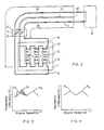
- Figure 3 shows the volumetric efficiency ⁇ relative to the engine speed N of the engine 1 with the resonance pipes 13, 14 of different length.
- the peak volumetric efficiency ⁇ in lower engine speed range as a result of resonance supercharging effect is separated into two peaks; the P1 by the cylinder row 2 and the P2 by the row 3.
- the deviation of intake air distribution between the two cylinder rows can lead to variations of generating torque from the cylinders between the two rows, increased engine vibrations and a poor feeling of vehicle driving.
- the control by calculation of fuel flow rate based on the total air flow rate in the engine as a whole does not serve to ensure a constant fuel-air ratio for each cylinder, because of the difference in volumetric efficiency between the cylinders. This results in an increase of harmful components in exhaust gases, in addition to the above mentioned variations of generating torque.
- the peak volumetric efficiency P3 in the characteristic curve shown in Figure 3 corresponds to the occurrence of inertia supercharging, in high engine speed, of the inlet passage 21 which connects th surge tank to each cylinder.
- Japanese patent unexamined publication no. 55-19976 disclises a proposed intake system for elimination of the deviated distribution of intake air over two rows of engine cylinders. It includes resonance passage portions of different length connected to the two cylinder rows. These portions have different sectional areas for correcting the length difference to attain resonance speed synchronism. However, the volumetric efficiency when inertia supercharging takes place does not show the same value between the two cylinder rows. Therefore, the proposed system does not provide a satisfactory result to eliminate the problem of deviated air distribution.
- an object of this invention to provide an intake system of a multicylinder internal combustion engine having two or more rows of cylinders which can overcome the above described problems of the conventional system by preventing the separation of peak volumetric efficiency into two ones as well as the deviation of intake air distribution, due to the effect of resonance supercharging in the multicylinder internal combustion engine's low-speed range, and by reducing variations of generating torque from the cylinders and resultant engine vibrations for a better feeling of vehicle driving.
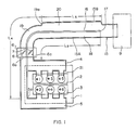
- a V-type multicylinder internal combustion engine 1 with two banks consists of two rows of cylinders; one cylinder row 2 including cylinders #1, #3, #5 and the other cylinder row 3 including cylinders #2, #4, #6.
- Surge tanks 4, 5 are provided to the two cylinder groups 2, 3, respectively, and operate for uniform distribution of intake air to the cylinders as well as for adjustment of resonance supercharging.
- a throttle valve unit 6 having twin throttle valves 7, 8 is installed near the outside or upper portion of the cylinder group 2 on one side of the engine 1 because of the engine type and the limitations of vehicle installation. Inside the unit 6, there are two intake air paths 6a, 6b where a throttle valve is provided respectively so as to enable synchronous rotation of the valves.
- An intake passage 15 is connected at one end to an air cleaner 9 and has two separate sections divided by a separating wall 16 which lead through the intake air paths 6a, 6b to surge tanks 4, 5 for the rows 2, 3, respectively.
- One of the two sections of said intake passage 15 leading to the cylinder group 2 has a resonance portion 18 of length L3 which extends from the end 17 of the wall 16 to the surge tank 4.
- the other section of said intake passage 15, leading to the cylinder group 3, includes a resonance portion 19 which extends from the connection end 5a for the surge tank 5, by a length L4 nearly equal to the length L3 of said portion 18.
- Said section of intake passage for the group 3 also includes a pressure wave inversion portion 20, extending from the end 19a of the resonance portion 19 at least to the wall end 17 of the separating wall 16, which has a cross-sectional area, about two times greater than the cross-sectional area S2 of the resonance portion 19, that allows inversion of intake pressure waves.
- the intake system of the multicylinder internal combustion engine thus constructed in accordance with the invention, comprises an intake passage having two resonance portions of nearly equal lenght leading to the cylinder rows 2, 3, one of said two portions having the pressure wave inversion portion 20, extending from the resonance portion 19 to the end of the separating wall 16, which has a sectional area that allows inversion of intake pressure waves.
- the volumetric efficiency therefore, as shown in Figure 4, exhibits the sole peak P4 in low engine speed which corresponds to the occurrence of resonance supercharging putting nearly the same effect on the resonance portions 18, 19. This helps minimize the deviation of intake air distribution and reduce the variations of generating torque by the two rows of cylinders, thereby resulting in decreased engine vibrations and a better feeling of vehicle operation.
- the peak P5 of the volumetric efficiency in high engine speed corresponds to the occurrence of inertia supercharging in the inlet passage 21 which connects the surge tank to each cylinder.
- a multicylinder internal combustion engine with the surge tanks 4, 5 provided on the cylinder rows 2, 3 is described, but it should be understood to those skilled in the art that the present invention is also applicable to an internal combustion engine having no surge tank.
- the intake pipe including a pressure wave inversion portion 20 which extends from the resonance portion 19 to the upstream-side end 17 of the separating wall 16. It is obvious, however, that when necessary the portion 20 can be extended further beyond the wall end 17.
- the intake system of multicylinder internal combustion engine includes a throttle valve unit provided on the side of one cylinder row of the two rows in the engine and an intake passage having first and second sections of different length separated by a separating wall leading to the two rows of cylinders, said first section for the cylinders of one row having a first resonance portion and said second section for the cylinders of the other row having a second resonance portion nearly equal in length to said first resonance portion and a pressure wave inversion portion extending from said second resonance portion at least to the upstream-side end of said separating wall and having a cross-sectional area that allows inversion of intake pressure waves.
- the present invention accordingly makes the effects of resonance super-charging in the two separate sections of the intake pipe for the two cylinder rows nearly equal, and thereby prevents the peak volumetric efficiency from separating into two ones as well as reduces the deviation of intake air distribution, even when the layout restriction depending on the engine type or the limitations on vehicle installation requires the installation of the throttle valve unit on the side of the cylinders of one row in the engine and therefore the use of an intake passage having two sections of different length. Consequently, the intake system in accordance with the invention ensures smaller variations of generating torque from the two rows of cylinders and a better feeling of vehicle operation.
- FIG. 5 shows the second embodiment of the present invention.
- An intake pipe 150 consists of two separate intake air pipes 150A, 150B which extend from the cylinder rows 2, 3 to the upstream-side end 170.
- the intake air pipe 150A for the cylinder row 2 comprises a first pesonance portion 180 having a length L3.
- the intake air pipe 150B for the cylinder row 3 comprises a second resonance portion 190 having a length L4 nearly equal to the lenght L3, and a pressure wave inversion portion 200 which extends from the end 190a of the second resonance portion 190 at least to the upstream-side end 170 of the two pipes 150A, 150B and has a cross-sectional area that allows inversion of intake pressure waves.
- the layout of the second embodiment's intake system in the engine can be more flexibly determined.
Landscapes
- Engineering & Computer Science (AREA)
- Chemical & Material Sciences (AREA)
- Combustion & Propulsion (AREA)
- Mechanical Engineering (AREA)
- General Engineering & Computer Science (AREA)
- Characterised By The Charging Evacuation (AREA)
Applications Claiming Priority (2)
| Application Number | Priority Date | Filing Date | Title |
|---|---|---|---|
| JP268678/88 | 1988-10-25 | ||
| JP26867888A JPH0723695B2 (ja) | 1988-10-25 | 1988-10-25 | 多気筒内燃機関の吸気装置 |
Publications (3)
| Publication Number | Publication Date |
|---|---|
| EP0366358A2 true EP0366358A2 (fr) | 1990-05-02 |
| EP0366358A3 EP0366358A3 (en) | 1990-08-16 |
| EP0366358B1 EP0366358B1 (fr) | 1995-09-20 |
Family
ID=17461872
Family Applications (1)
| Application Number | Title | Priority Date | Filing Date |
|---|---|---|---|
| EP89310756A Expired - Lifetime EP0366358B1 (fr) | 1988-10-25 | 1989-10-19 | Système d'admission pour un moteur à combustion interne à plusieurs cylindres |
Country Status (4)
| Country | Link |
|---|---|
| US (1) | US4938177A (fr) |
| EP (1) | EP0366358B1 (fr) |
| JP (1) | JPH0723695B2 (fr) |
| DE (1) | DE68924320T2 (fr) |
Families Citing this family (4)
| Publication number | Priority date | Publication date | Assignee | Title |
|---|---|---|---|---|
| US5056472A (en) * | 1989-06-06 | 1991-10-15 | Mazda Motor Corporation | 4-cycle 12-cylinder engine |
| JP3787915B2 (ja) * | 1996-09-04 | 2006-06-21 | 豊田合成株式会社 | 内燃機関の吸気管 |
| DE19842724A1 (de) * | 1998-09-18 | 2000-03-23 | Porsche Ag | Sauganlage |
| FI114332B (fi) * | 2000-11-08 | 2004-09-30 | Waertsilae Finland Oy | Ahdetun mäntämoottorin ilmansyöttöjärjestely ja -menetelmä ahdetun mäntämoottorin yhteydessä |
Family Cites Families (5)
| Publication number | Priority date | Publication date | Assignee | Title |
|---|---|---|---|---|
| AT330506B (de) * | 1971-09-28 | 1976-07-12 | Autoipari Kutato Intezet | Kolbenbrennkraftmaschine mit abgasturboaufladung |
| US4064696A (en) * | 1975-05-13 | 1977-12-27 | Autoipari Kutato Intezet | Live-gas conduit system for turbocharged six-cylinder engines |
| HU175877B (en) * | 1978-07-07 | 1980-11-28 | Autoipari Kutato Intezet | Fresh gas duct system of resanator for internal combustion piston engines |
| JPS59168529U (ja) * | 1983-04-28 | 1984-11-12 | いすゞ自動車株式会社 | 内燃機関の慣性過給装置 |
| JPH0528338Y2 (fr) * | 1986-11-06 | 1993-07-21 |
-
1988
- 1988-10-25 JP JP26867888A patent/JPH0723695B2/ja not_active Expired - Lifetime
-
1989
- 1989-10-17 US US07/422,528 patent/US4938177A/en not_active Expired - Fee Related
- 1989-10-19 EP EP89310756A patent/EP0366358B1/fr not_active Expired - Lifetime
- 1989-10-19 DE DE68924320T patent/DE68924320T2/de not_active Expired - Fee Related
Also Published As
| Publication number | Publication date |
|---|---|
| US4938177A (en) | 1990-07-03 |
| EP0366358A3 (en) | 1990-08-16 |
| EP0366358B1 (fr) | 1995-09-20 |
| DE68924320T2 (de) | 1996-05-15 |
| DE68924320D1 (de) | 1995-10-26 |
| JPH02115521A (ja) | 1990-04-27 |
| JPH0723695B2 (ja) | 1995-03-15 |
Similar Documents
| Publication | Publication Date | Title |
|---|---|---|
| US5121733A (en) | Air intake system for supercharged engine | |
| EP0330302B1 (fr) | Moteur avec passage d'admission à section variable | |
| US4617896A (en) | Internal combustion engine having three intake valves per cylinder | |
| US4765285A (en) | Intake system for internal combustion engine | |
| JPS62210219A (ja) | 内燃機関の吸気装置 | |
| JPS6119927A (ja) | 多気筒内燃機関の吸気装置 | |
| US4867109A (en) | Intake passage arrangement for internal combustion engines | |
| US4116172A (en) | Naturally aspirated eight cylinder internal combustion engine | |
| US4515115A (en) | Inertia supercharger for internal combustion engines | |
| US4977865A (en) | Intake system for V-type engine | |
| US5056472A (en) | 4-cycle 12-cylinder engine | |
| US4627400A (en) | Porting system for internal combustion engine | |
| JP3119925B2 (ja) | エンジンの制御装置 | |
| EP0366358A2 (fr) | Système d'admission pour un moteur à combustion interne à plusieurs cylindres | |
| US5085178A (en) | Intake piping structure for multi-cylinder engine | |
| JP2903726B2 (ja) | 内燃機関の可変吸気装置 | |
| US4912930A (en) | High performance exhaust system for internal combustion engine | |
| GB2079370A (en) | Multi-cylinder reciprocating engine with resonance charging | |
| EP0278032B1 (fr) | Système d'échappement à haute performance pour moteur à combustion interne | |
| JPH05332188A (ja) | エンジンの燃焼制御装置 | |
| US4471615A (en) | Turbo and inertia supercharger | |
| US5542386A (en) | Intake system for multiple cylinder combustion engines | |
| JP3285908B2 (ja) | 過給機付きエンジン | |
| EP1034363B1 (fr) | Moteur a combustion interne comprenant au moins un cylindre ainsi que des passages d'admission distincts | |
| EP0278033A1 (fr) | Système d'échappement à haute performance pour moteur à combustion interne |
Legal Events
| Date | Code | Title | Description |
|---|---|---|---|
| PUAI | Public reference made under article 153(3) epc to a published international application that has entered the european phase |
Free format text: ORIGINAL CODE: 0009012 |
|
| AK | Designated contracting states |
Kind code of ref document: A2 Designated state(s): DE GB |
|
| PUAL | Search report despatched |
Free format text: ORIGINAL CODE: 0009013 |
|
| AK | Designated contracting states |
Kind code of ref document: A3 Designated state(s): DE GB |
|
| 17P | Request for examination filed |
Effective date: 19910215 |
|
| 17Q | First examination report despatched |
Effective date: 19920324 |
|
| GRAA | (expected) grant |
Free format text: ORIGINAL CODE: 0009210 |
|
| AK | Designated contracting states |
Kind code of ref document: B1 Designated state(s): DE GB |
|
| REF | Corresponds to: |
Ref document number: 68924320 Country of ref document: DE Date of ref document: 19951026 |
|
| PGFP | Annual fee paid to national office [announced via postgrant information from national office to epo] |
Ref country code: GB Payment date: 19960314 Year of fee payment: 7 |
|
| PG25 | Lapsed in a contracting state [announced via postgrant information from national office to epo] |
Ref country code: DE Effective date: 19960702 |
|
| PLBE | No opposition filed within time limit |
Free format text: ORIGINAL CODE: 0009261 |
|
| STAA | Information on the status of an ep patent application or granted ep patent |
Free format text: STATUS: NO OPPOSITION FILED WITHIN TIME LIMIT |
|
| 26N | No opposition filed | ||
| PG25 | Lapsed in a contracting state [announced via postgrant information from national office to epo] |
Ref country code: GB Effective date: 19961019 |
|
| GBPC | Gb: european patent ceased through non-payment of renewal fee |
Effective date: 19961019 |