EP0366019A1 - Teilverdampfer - Google Patents
Teilverdampfer Download PDFInfo
- Publication number
- EP0366019A1 EP0366019A1 EP89119519A EP89119519A EP0366019A1 EP 0366019 A1 EP0366019 A1 EP 0366019A1 EP 89119519 A EP89119519 A EP 89119519A EP 89119519 A EP89119519 A EP 89119519A EP 0366019 A1 EP0366019 A1 EP 0366019A1
- Authority
- EP
- European Patent Office
- Prior art keywords
- vaporizing
- tanks
- original fluid
- tank
- partition wall
- Prior art date
- Legal status (The legal status is an assumption and is not a legal conclusion. Google has not performed a legal analysis and makes no representation as to the accuracy of the status listed.)
- Withdrawn
Links
Images


Classifications
-
- B—PERFORMING OPERATIONS; TRANSPORTING
- B01—PHYSICAL OR CHEMICAL PROCESSES OR APPARATUS IN GENERAL
- B01D—SEPARATION
- B01D3/00—Distillation or related exchange processes in which liquids are contacted with gaseous media, e.g. stripping
- B01D3/14—Fractional distillation or use of a fractionation or rectification column
- B01D3/32—Other features of fractionating columns ; Constructional details of fractionating columns not provided for in groups B01D3/16 - B01D3/30
- B01D3/322—Reboiler specifications
Definitions
- the present invention relates to a partial vaporizer for continuously carrying out a vaporizing operation.
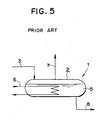
- Partial vaporizer 1 as shown in Fig.5 has been hitherto pointed out as a partial vaporizer for contiuously carrying out a vaporizing operation.
- original fluid is continuously fed from feed pipe 3 connected to an upper portion of vaporizing section 2 and steam is fed to heating medium pipe 6. Vapor produced from the original fluid is taken out through tube 7 on the upper side of the vaporizing section. Concentrated fluid, from which components of low boiling point have vaporized, is taken out through tube 8 at the bottom of the vaporizing section.
- the present invention provides a partial vaporizer, wherein original fluid is continuously fed, fed original fluid is heated and components of low boiling point of the original fluid are vaporized, comprisising: at least two vaporising tanks, into which a vaporizing section is divided with a partition wall, original fluid flowing from an upper vaporizing tank to a lower vaporizing tank; a heating medium pipe for heating the original fluid, which is arranged in each of the vaporizing tanks; a tube for taking produced vapor out of each of the vaporizing tanks; and a tube for taking bottoms out of the lowest vaporizing tank.
- the present invention wherein original fluid is continuously fed, fed original fluid is heated and components of low boiling point of the original fluid is vaporized, comprising: at least two vaporizing tanks, into which a vaporizing section is divided with a partition wall, the original fluid flowing from an upper vaporizing tank to a lower vaporizing tank; a heating medium pipe for heating the original fluid which is arranged in each of the vaporizing tanks; a partition wall which divides a vapor-phase portion of a vaporizing section, vapor produced out of each of the vaporizing tanks not mixing with one another thanks to the partition wall; tubes for taking produced vapor out of each of the vaporizing tanks separately; and a tube for taking bottoms out of the lowest vaporizing tank.
- a partial vaporizer of the present invention the following measures are desired to be taken so as to obtain bottoms having the same components as those of bottoms obtained by the prior art vaporizer:
- hold-up in each of vaporizing tanks upper than the lowest vaporizing tank is at least richer in components of low boiling point than hold-up in the lowest vaporizing tank. Accordingly, the components of low boiling point can be vaporized by a smaller amount of heating medium in those vaporizing tanks than that in the lowest vaporizing tank.
- the total vaporizing tanks being taken into consideration, the total amount of heating medium can be decreased, whereby an object of energy saving can be accomplished. That is to say, entropy loss is produced by mixing fluids having different components, but separation capability of a separation system is increased by decreasing this entropy loss.
- the amount of heating medium can be further decreased by dividing vapor-phase portion in accordance with each vaporizing tank and keeping vapor-liquid equilibrium state in each vaporizing tank.
- Vaporizing section 12 of reboiler 10 is divided into two vaporizing tanks 21 and 22 by means of partition wall 26 dividing liquid-phase portion.
- Hold-up in rectifiction column 20 flows into vaporizing tank 21 on the left side of the vaporizing section through tube 3.
- Liquid having overflowed the vaporizing tank 21 flows into the vaporizing tank 22 on the right side of the vaporizing section.
- Steam tubes 31 and 32 for exchanging heat with the liquid through heating medium are connected to each of the vaporizing tanks 21 and 22.
- Vapor produced out of each of the vaporizing tanks is blown into a bottom portion of the rectification column through tube 7. Bottoms are taken out of the bottom of the vaporizing tank 22. When concentration of the bottoms is controlled to a predetermined value, a smaller amount of steam is used than that in the prior art vaporizer, whereby an energy saving can be accomplished.
- Fig.2 is a schematic view illustrating an example of the case where liquid-phase portion of the vaporizing section 12 in the reboiler 10 is divided into three portions of the vaporizing tanks 21, 22 and 23 by means of partition walls 26 and 27. Steam tubes 31, 32 and 33 are connected to each of the vaporizing tanks 21, 22 and 23, respectively.
- partition wall 46 is arranged in vapor-phase portion of the vaporizing section 12 and vapor produced out of each of the vaporizing tanks is taken out through tubes 41 and 42 without mixing with one another. Since a vapor-liquid equilibrium state can be kept in each vaporizing tank, the amount of steam can be further decreased.
- Fig.4 is a schematic view illustrating the case where liquid-phase portion of the vaporizing section is divided into three portions by partition walls 26 and 27 and a vapor-phase portion is divided into three portions by partition walls 46 and 47.
- Steam tubes 31, 32 and 33 are connected to each of the vaporizing tanks 31, 32 and 33, respectively. Vapor produced out of each of the vaporizing tanks 21, 22 and 23 is taken through tubes 41, 42 and 43.
Landscapes
- Chemical & Material Sciences (AREA)
- Chemical Kinetics & Catalysis (AREA)
- Filling Or Discharging Of Gas Storage Vessels (AREA)
- Vaporization, Distillation, Condensation, Sublimation, And Cold Traps (AREA)
Applications Claiming Priority (2)
| Application Number | Priority Date | Filing Date | Title |
|---|---|---|---|
| JP26537788A JPH02115001A (ja) | 1988-10-21 | 1988-10-21 | 部分蒸発器 |
| JP265377/88 | 1988-10-21 |
Publications (1)
| Publication Number | Publication Date |
|---|---|
| EP0366019A1 true EP0366019A1 (de) | 1990-05-02 |
Family
ID=17416337
Family Applications (1)
| Application Number | Title | Priority Date | Filing Date |
|---|---|---|---|
| EP89119519A Withdrawn EP0366019A1 (de) | 1988-10-21 | 1989-10-20 | Teilverdampfer |
Country Status (2)
| Country | Link |
|---|---|
| EP (1) | EP0366019A1 (de) |
| JP (1) | JPH02115001A (de) |
Cited By (3)
| Publication number | Priority date | Publication date | Assignee | Title |
|---|---|---|---|---|
| WO2017005565A1 (de) * | 2015-07-03 | 2017-01-12 | Basf Se | Destillationseinrichtung umfassend eine kolonne, mit drei oder mehreren hintereinander flüssigkeitsdurchströmten zellen und verfahren zur destillation oder extraktivdestillation unter verwendung der destillationseinrichtung |
| WO2017134143A1 (de) * | 2016-02-05 | 2017-08-10 | Basf Se | Verfahren zur trennung von stoffen durch extraktivdestillation |
| EP4461395A1 (de) * | 2023-05-12 | 2024-11-13 | Limón GmbH | Verfahren und vorrichtung zur trennung eines einen leichtsieder und einen schwersieder umfassenden gemisches mittels einer rektifikationskolonne |
Citations (1)
| Publication number | Priority date | Publication date | Assignee | Title |
|---|---|---|---|---|
| US2578469A (en) * | 1948-04-07 | 1951-12-11 | Pure Oil Co | Differential pressure distilling apparatus and method |
Family Cites Families (2)
| Publication number | Priority date | Publication date | Assignee | Title |
|---|---|---|---|---|
| JPS53138984A (en) * | 1977-05-12 | 1978-12-04 | Gadelius Co Ltd | Solution concentration |
| JPS5480278A (en) * | 1977-12-09 | 1979-06-26 | Sasakura Eng Co Ltd | Vertical multiipurpose evaporator |
-
1988
- 1988-10-21 JP JP26537788A patent/JPH02115001A/ja active Pending
-
1989
- 1989-10-20 EP EP89119519A patent/EP0366019A1/de not_active Withdrawn
Patent Citations (1)
| Publication number | Priority date | Publication date | Assignee | Title |
|---|---|---|---|---|
| US2578469A (en) * | 1948-04-07 | 1951-12-11 | Pure Oil Co | Differential pressure distilling apparatus and method |
Cited By (8)
| Publication number | Priority date | Publication date | Assignee | Title |
|---|---|---|---|---|
| WO2017005565A1 (de) * | 2015-07-03 | 2017-01-12 | Basf Se | Destillationseinrichtung umfassend eine kolonne, mit drei oder mehreren hintereinander flüssigkeitsdurchströmten zellen und verfahren zur destillation oder extraktivdestillation unter verwendung der destillationseinrichtung |
| CN107847809A (zh) * | 2015-07-03 | 2018-03-27 | 巴斯夫欧洲公司 | 包括具有液体依次流经的三个或更多个隔室的塔的蒸馏设备和用于使用该蒸馏设备进行蒸馏或萃取蒸馏的方法 |
| US10569192B2 (en) | 2015-07-03 | 2020-02-25 | Basf Se | Distillation device comprising a column which as three or a plurality of cells in series through which fluid flows and method for distilling or extractive distillation by use of the distillation device |
| RU2720775C2 (ru) * | 2015-07-03 | 2020-05-13 | Басф Се | Дистилляционное устройство, включающее колонну с тремя или более отделениями, выполненными с возможностью последовательного протекания через них жидкости, и способ дистилляции или экстрактивной дистилляции с применением дистилляционного устройства |
| CN107847809B (zh) * | 2015-07-03 | 2021-01-15 | 巴斯夫欧洲公司 | 包括具有液体依次流经的三个或更多个隔室的塔的蒸馏设备和用于使用该蒸馏设备进行蒸馏或萃取蒸馏的方法 |
| WO2017134143A1 (de) * | 2016-02-05 | 2017-08-10 | Basf Se | Verfahren zur trennung von stoffen durch extraktivdestillation |
| US10793494B2 (en) | 2016-02-05 | 2020-10-06 | Basf Se | Method for separating materials by means of an extractive distillation process |
| EP4461395A1 (de) * | 2023-05-12 | 2024-11-13 | Limón GmbH | Verfahren und vorrichtung zur trennung eines einen leichtsieder und einen schwersieder umfassenden gemisches mittels einer rektifikationskolonne |
Also Published As
| Publication number | Publication date |
|---|---|
| JPH02115001A (ja) | 1990-04-27 |
Similar Documents
| Publication | Publication Date | Title |
|---|---|---|
| US4230536A (en) | Method for the distillation purification of organic heat transfer fluids | |
| US4234391A (en) | Continuous distillation apparatus and method | |
| US4025398A (en) | Distillation processes and apparatus | |
| US3956061A (en) | Multi-stage processing and concentration of solutions | |
| US3274752A (en) | Process and apparatus for improving the transfer of heat from a hot gaseous fluid | |
| DK455383D0 (da) | Anlaeg til fremstilling af gasformig nitrogen | |
| EP0102190A3 (de) | Anlage zur Herstellung von gasförmigem Sauerstoff | |
| EP0726085A1 (de) | Destillationskolonne mit innerem wärmeaustausch | |
| Lynd et al. | Distillation with intermediate heat pumps and optimal sidestream return | |
| US4285774A (en) | Microwave distillation | |
| EP0366019A1 (de) | Teilverdampfer | |
| US4308107A (en) | Distillation process and apparatus for its realization | |
| US2895546A (en) | Method and apparatus for recompression evaporation | |
| US5303769A (en) | Integrated thermosiphon heat exchanger apparatus | |
| JP2694425B2 (ja) | 内部熱交換型蒸留塔 | |
| US3833479A (en) | Methods and means for distillation of liquids | |
| US6365006B1 (en) | Method for distilling a mixture of substances and device for realizing the same | |
| US3230158A (en) | Method and apparatus for reboiling a heated system | |
| US2398184A (en) | Apparatus for distillation | |
| US1960809A (en) | Refrigerating apparatus | |
| US3248304A (en) | Fluid control for steam compressor type distillation apparatus | |
| US4016028A (en) | Multiple effect processes of concentrating solutions | |
| Antonelli et al. | Design and application considerations for heat exchangers with enhanced boiling surfaces | |
| CN207429733U (zh) | 一种用于制备西瓜酮的精馏设备 | |
| US2395004A (en) | Method of and apparatus for evaporating liquids and condensing vapors |
Legal Events
| Date | Code | Title | Description |
|---|---|---|---|
| PUAI | Public reference made under article 153(3) epc to a published international application that has entered the european phase |
Free format text: ORIGINAL CODE: 0009012 |
|
| 17P | Request for examination filed |
Effective date: 19891020 |
|
| AK | Designated contracting states |
Kind code of ref document: A1 Designated state(s): DE GB |
|
| RAP1 | Party data changed (applicant data changed or rights of an application transferred) |
Owner name: NKK CORPORATION Owner name: NAKA, YUJI |
|
| 17Q | First examination report despatched |
Effective date: 19920131 |
|
| STAA | Information on the status of an ep patent application or granted ep patent |
Free format text: STATUS: THE APPLICATION IS DEEMED TO BE WITHDRAWN |
|
| 18D | Application deemed to be withdrawn |
Effective date: 19930612 |