EP0366019A1 - Partial vaporizer - Google Patents
Partial vaporizer Download PDFInfo
- Publication number
- EP0366019A1 EP0366019A1 EP89119519A EP89119519A EP0366019A1 EP 0366019 A1 EP0366019 A1 EP 0366019A1 EP 89119519 A EP89119519 A EP 89119519A EP 89119519 A EP89119519 A EP 89119519A EP 0366019 A1 EP0366019 A1 EP 0366019A1
- Authority
- EP
- European Patent Office
- Prior art keywords
- vaporizing
- tanks
- original fluid
- tank
- partition wall
- Prior art date
- Legal status (The legal status is an assumption and is not a legal conclusion. Google has not performed a legal analysis and makes no representation as to the accuracy of the status listed.)
- Withdrawn
Links
Images


Classifications
-
- B—PERFORMING OPERATIONS; TRANSPORTING
- B01—PHYSICAL OR CHEMICAL PROCESSES OR APPARATUS IN GENERAL
- B01D—SEPARATION
- B01D3/00—Distillation or related exchange processes in which liquids are contacted with gaseous media, e.g. stripping
- B01D3/14—Fractional distillation or use of a fractionation or rectification column
- B01D3/32—Other features of fractionating columns ; Constructional details of fractionating columns not provided for in groups B01D3/16 - B01D3/30
- B01D3/322—Reboiler specifications
Definitions
- the present invention relates to a partial vaporizer for continuously carrying out a vaporizing operation.
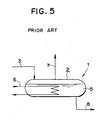
- Partial vaporizer 1 as shown in Fig.5 has been hitherto pointed out as a partial vaporizer for contiuously carrying out a vaporizing operation.
- original fluid is continuously fed from feed pipe 3 connected to an upper portion of vaporizing section 2 and steam is fed to heating medium pipe 6. Vapor produced from the original fluid is taken out through tube 7 on the upper side of the vaporizing section. Concentrated fluid, from which components of low boiling point have vaporized, is taken out through tube 8 at the bottom of the vaporizing section.
- the present invention provides a partial vaporizer, wherein original fluid is continuously fed, fed original fluid is heated and components of low boiling point of the original fluid are vaporized, comprisising: at least two vaporising tanks, into which a vaporizing section is divided with a partition wall, original fluid flowing from an upper vaporizing tank to a lower vaporizing tank; a heating medium pipe for heating the original fluid, which is arranged in each of the vaporizing tanks; a tube for taking produced vapor out of each of the vaporizing tanks; and a tube for taking bottoms out of the lowest vaporizing tank.
- the present invention wherein original fluid is continuously fed, fed original fluid is heated and components of low boiling point of the original fluid is vaporized, comprising: at least two vaporizing tanks, into which a vaporizing section is divided with a partition wall, the original fluid flowing from an upper vaporizing tank to a lower vaporizing tank; a heating medium pipe for heating the original fluid which is arranged in each of the vaporizing tanks; a partition wall which divides a vapor-phase portion of a vaporizing section, vapor produced out of each of the vaporizing tanks not mixing with one another thanks to the partition wall; tubes for taking produced vapor out of each of the vaporizing tanks separately; and a tube for taking bottoms out of the lowest vaporizing tank.
- a partial vaporizer of the present invention the following measures are desired to be taken so as to obtain bottoms having the same components as those of bottoms obtained by the prior art vaporizer:
- hold-up in each of vaporizing tanks upper than the lowest vaporizing tank is at least richer in components of low boiling point than hold-up in the lowest vaporizing tank. Accordingly, the components of low boiling point can be vaporized by a smaller amount of heating medium in those vaporizing tanks than that in the lowest vaporizing tank.
- the total vaporizing tanks being taken into consideration, the total amount of heating medium can be decreased, whereby an object of energy saving can be accomplished. That is to say, entropy loss is produced by mixing fluids having different components, but separation capability of a separation system is increased by decreasing this entropy loss.
- the amount of heating medium can be further decreased by dividing vapor-phase portion in accordance with each vaporizing tank and keeping vapor-liquid equilibrium state in each vaporizing tank.
- Vaporizing section 12 of reboiler 10 is divided into two vaporizing tanks 21 and 22 by means of partition wall 26 dividing liquid-phase portion.
- Hold-up in rectifiction column 20 flows into vaporizing tank 21 on the left side of the vaporizing section through tube 3.
- Liquid having overflowed the vaporizing tank 21 flows into the vaporizing tank 22 on the right side of the vaporizing section.
- Steam tubes 31 and 32 for exchanging heat with the liquid through heating medium are connected to each of the vaporizing tanks 21 and 22.
- Vapor produced out of each of the vaporizing tanks is blown into a bottom portion of the rectification column through tube 7. Bottoms are taken out of the bottom of the vaporizing tank 22. When concentration of the bottoms is controlled to a predetermined value, a smaller amount of steam is used than that in the prior art vaporizer, whereby an energy saving can be accomplished.
- Fig.2 is a schematic view illustrating an example of the case where liquid-phase portion of the vaporizing section 12 in the reboiler 10 is divided into three portions of the vaporizing tanks 21, 22 and 23 by means of partition walls 26 and 27. Steam tubes 31, 32 and 33 are connected to each of the vaporizing tanks 21, 22 and 23, respectively.
- partition wall 46 is arranged in vapor-phase portion of the vaporizing section 12 and vapor produced out of each of the vaporizing tanks is taken out through tubes 41 and 42 without mixing with one another. Since a vapor-liquid equilibrium state can be kept in each vaporizing tank, the amount of steam can be further decreased.
- Fig.4 is a schematic view illustrating the case where liquid-phase portion of the vaporizing section is divided into three portions by partition walls 26 and 27 and a vapor-phase portion is divided into three portions by partition walls 46 and 47.
- Steam tubes 31, 32 and 33 are connected to each of the vaporizing tanks 31, 32 and 33, respectively. Vapor produced out of each of the vaporizing tanks 21, 22 and 23 is taken through tubes 41, 42 and 43.
Landscapes
- Chemical & Material Sciences (AREA)
- Chemical Kinetics & Catalysis (AREA)
- Vaporization, Distillation, Condensation, Sublimation, And Cold Traps (AREA)
- Filling Or Discharging Of Gas Storage Vessels (AREA)
Abstract
A partial vaporizer comprises two vaporizing tanks (21),(22), into which a vaporizing section (12) is divided with a partition wall (26), original fluid flowing from an upper vaporizing tank (21) to a lower vaporizing tank (22), heating medium pipes (31), (32) for heating the original fluid which are arranged in each of the vaporizing tanks, a partition wall (46) dividing a vapor-phase portion of the vaporizing section, vapor produced out of each of the vaporizing tanks being not mixed with one another, tubes (41), (42) for taking produced vapor out of each of the vaporizing tanks and tube (8) for taking bottoms out of the lowest vaporizing tank.
Description
- The present invention relates to a partial vaporizer for continuously carrying out a vaporizing operation.
-
Partial vaporizer 1 as shown in Fig.5 has been hitherto pointed out as a partial vaporizer for contiuously carrying out a vaporizing operation. In this partial vaporizer, original fluid is continuously fed fromfeed pipe 3 connected to an upper portion of vaporizingsection 2 and steam is fed to heatingmedium pipe 6. Vapor produced from the original fluid is taken out through tube 7 on the upper side of the vaporizing section. Concentrated fluid, from which components of low boiling point have vaporized, is taken out throughtube 8 at the bottom of the vaporizing section. - Since heat of vaporization is required to be constantly fed in said partial vaporizer, a great amount of heat is required. In consequence, a problem how to heat the original fluid efficiently and economically is posed as a great problem.
- It is an object of the present invention to provide a partial vaporizer which can accomplish an object of energy saving by decreasing an amount of medium required for heating as a result of having increased an energy efficiency.
- To accomplish the above-mentioned object, the present invention provides a partial vaporizer, wherein original fluid is continuously fed, fed original fluid is heated and components of low boiling point of the original fluid are vaporized, comprisising:
at least two vaporising tanks, into which a vaporizing section is divided with a partition wall, original fluid flowing from an upper vaporizing tank to a lower vaporizing tank;
a heating medium pipe for heating the original fluid, which is arranged in each of the vaporizing tanks;
a tube for taking produced vapor out of each of the vaporizing tanks; and
a tube for taking bottoms out of the lowest vaporizing tank. - Further, the present invention, wherein original fluid is continuously fed, fed original fluid is heated and components of low boiling point of the original fluid is vaporized, comprising:
at least two vaporizing tanks, into which a vaporizing section is divided with a partition wall, the original fluid flowing from an upper vaporizing tank to a lower vaporizing tank;
a heating medium pipe for heating the original fluid which is arranged in each of the vaporizing tanks;
a partition wall which divides a vapor-phase portion of a vaporizing section, vapor produced out of each of the vaporizing tanks not mixing with one another thanks to the partition wall;
tubes for taking produced vapor out of each of the vaporizing tanks separately; and
a tube for taking bottoms out of the lowest vaporizing tank. - The above objects and other objects and advantages of the present invention will become apparent from the detailed description to follow, taken in connection with appended drawings.
- Fig.1 is an explanatory view of a partial vaporizer of the present invention;
- Fig.2 is an explanatory view of a further partial vaporizer of the present invention;
- Fig.3 is an explanatory view of a still further partial vaporizer of the present invention;
- Fig.4 is an explanatory view of another partial vaporizer of the present invention; and
- Fig.5 is an explanatory view of the prior art partial vaporizer.
- In a partial vaporizer of the present invention, the following measures are desired to be taken so as to obtain bottoms having the same components as those of bottoms obtained by the prior art vaporizer:
- (a) Components of hold-up in the lowest vaporizing tank out of at least two vaporizing tanks are made to be equal to components of hold-up in the prior art vaporizing section.
- (b) Hold-up in the lowest vaporizing tank is heated by the same amount of heating medium as that of heating medium in the prior art partial vaporizer.
- On the other hand, hold-up in each of vaporizing tanks upper than the lowest vaporizing tank is at least richer in components of low boiling point than hold-up in the lowest vaporizing tank. Accordingly, the components of low boiling point can be vaporized by a smaller amount of heating medium in those vaporizing tanks than that in the lowest vaporizing tank. The total vaporizing tanks being taken into consideration, the total amount of heating medium can be decreased, whereby an object of energy saving can be accomplished. That is to say, entropy loss is produced by mixing fluids having different components, but separation capability of a separation system is increased by decreasing this entropy loss.
- The amount of heating medium can be further decreased by dividing vapor-phase portion in accordance with each vaporizing tank and keeping vapor-liquid equilibrium state in each vaporizing tank.
- An example of the case where the partial vaporizer of the present invention is put into a rectification apparatus as a reboiler will be described with specific reference to Fig.1. Vaporizing
section 12 ofreboiler 10 is divided into two vaporizingtanks partition wall 26 dividing liquid-phase portion. Hold-up inrectifiction column 20 flows into vaporizingtank 21 on the left side of the vaporizing section throughtube 3. Liquid having overflowed the vaporizingtank 21 flows into the vaporizingtank 22 on the right side of the vaporizing section.Steam tubes tanks tank 22. When concentration of the bottoms is controlled to a predetermined value, a smaller amount of steam is used than that in the prior art vaporizer, whereby an energy saving can be accomplished. - Fig.2 is a schematic view illustrating an example of the case where liquid-phase portion of the vaporizing
section 12 in thereboiler 10 is divided into three portions of the vaporizingtanks partition walls Steam tubes tanks - Subsequently, another example of the present invention will be described. In this example,
partition wall 46 is arranged in vapor-phase portion of the vaporizingsection 12 and vapor produced out of each of the vaporizing tanks is taken out throughtubes - Fig.4 is a schematic view illustrating the case where liquid-phase portion of the vaporizing section is divided into three portions by
partition walls partition walls Steam tubes tanks tanks tubes - Reference signs in the claims are intended for better understanding and shall not limit the scope.
Claims (6)
1. A partial vaporizer, wherein original fluid is continuously fed, fed original fluid is heated and components of low boiling point of the original fluid are vaporized, characterized by comprising:
at least two vaporizing tanks (21), (22), into which a vaporizing section (12) is divided with a partition wall (26), original fluid flowing from an upper vaporizing tank (21) to a lower vaporizing tank (22);
heating medium pipes (31),(32) for heating the original luid, which are arranged in each of the vaporizing tanks;
a tube (7) for taking produced vapor out of each of the vaporizing tanks; and
a tube (8) for taking bottoms out of the lowest vaporizing tank.
2. The vaporizer of claim 1, characterized in that said vaporizing tanks are three tanks (21), (22), (23), into which the vaporizing section is divided with the partition wall.
3. The vaporizer of claim 1, characterized in that said heating medium pipe is a steam tube.
4. A partial vaporizer, wherein original fluid is continuously fed, fed original fluid is heated and components of low boiling point of the original fluid is vaporized, characterized by comprising;
at least two vaporizing tanks (21), (22), into which a vaporizing section is divided with a partition wall (26), the original fluid flowing from an upper vaporizing tank (21) to a lower vaporizing tank (22);
heating medium pipes (31), (32) for heating the original fluid which are arranged in each of the vaporizing tanks;
a partition wall (46) which divides a vapor-phase portion of a vaporizing section, vapor produced out of each of the vaporizing tanks not mixing with one another thanks to the partition wall;
tubes (41), (42) for taking produced vapor out of each of the vaporizing tanks separately; and
a tube (8) for taking bottoms out of the lowest vaporizing tank.
5. The vaporizer of claim 4, characterized in that said vaporizing tanks are three tanks (21), (22), (23), into which the vaporizing section is divided with the partition wall.
6. The vaporizer of claim 4, characterized in that said heating medium pipe is a steam tube.
Applications Claiming Priority (2)
| Application Number | Priority Date | Filing Date | Title |
|---|---|---|---|
| JP26537788A JPH02115001A (en) | 1988-10-21 | 1988-10-21 | Partial evaporator |
| JP265377/88 | 1988-10-21 |
Publications (1)
| Publication Number | Publication Date |
|---|---|
| EP0366019A1 true EP0366019A1 (en) | 1990-05-02 |
Family
ID=17416337
Family Applications (1)
| Application Number | Title | Priority Date | Filing Date |
|---|---|---|---|
| EP89119519A Withdrawn EP0366019A1 (en) | 1988-10-21 | 1989-10-20 | Partial vaporizer |
Country Status (2)
| Country | Link |
|---|---|
| EP (1) | EP0366019A1 (en) |
| JP (1) | JPH02115001A (en) |
Cited By (2)
| Publication number | Priority date | Publication date | Assignee | Title |
|---|---|---|---|---|
| WO2017005565A1 (en) * | 2015-07-03 | 2017-01-12 | Basf Se | Distillation device comprising a column which has three or a plurality of cells in series through which fluid flows and method for distilling or extractive distillation by use of the distillation device |
| WO2017134143A1 (en) * | 2016-02-05 | 2017-08-10 | Basf Se | Method for separating materials by means of an extractive distillation process |
Citations (1)
| Publication number | Priority date | Publication date | Assignee | Title |
|---|---|---|---|---|
| US2578469A (en) * | 1948-04-07 | 1951-12-11 | Pure Oil Co | Differential pressure distilling apparatus and method |
Family Cites Families (2)
| Publication number | Priority date | Publication date | Assignee | Title |
|---|---|---|---|---|
| JPS53138984A (en) * | 1977-05-12 | 1978-12-04 | Gadelius Co Ltd | Solution concentration |
| JPS5480278A (en) * | 1977-12-09 | 1979-06-26 | Sasakura Eng Co Ltd | Vertical multiipurpose evaporator |
-
1988
- 1988-10-21 JP JP26537788A patent/JPH02115001A/en active Pending
-
1989
- 1989-10-20 EP EP89119519A patent/EP0366019A1/en not_active Withdrawn
Patent Citations (1)
| Publication number | Priority date | Publication date | Assignee | Title |
|---|---|---|---|---|
| US2578469A (en) * | 1948-04-07 | 1951-12-11 | Pure Oil Co | Differential pressure distilling apparatus and method |
Cited By (7)
| Publication number | Priority date | Publication date | Assignee | Title |
|---|---|---|---|---|
| WO2017005565A1 (en) * | 2015-07-03 | 2017-01-12 | Basf Se | Distillation device comprising a column which has three or a plurality of cells in series through which fluid flows and method for distilling or extractive distillation by use of the distillation device |
| CN107847809A (en) * | 2015-07-03 | 2018-03-27 | 巴斯夫欧洲公司 | Including the distillation equipment of the towers of three or more compartments that is flowed through successively with liquid and for being distilled using the distillation equipment or the method for extractive distillation |
| US10569192B2 (en) | 2015-07-03 | 2020-02-25 | Basf Se | Distillation device comprising a column which as three or a plurality of cells in series through which fluid flows and method for distilling or extractive distillation by use of the distillation device |
| RU2720775C2 (en) * | 2015-07-03 | 2020-05-13 | Басф Се | Distillation device comprising column with three or more compartments configured to sequentially flow liquids therethrough, and distillation or extractive distillation method using distillation apparatus |
| CN107847809B (en) * | 2015-07-03 | 2021-01-15 | 巴斯夫欧洲公司 | Distillation apparatus comprising a column having three or more compartments through which a liquid flows in sequence and process for carrying out a distillation or extractive distillation using such a distillation apparatus |
| WO2017134143A1 (en) * | 2016-02-05 | 2017-08-10 | Basf Se | Method for separating materials by means of an extractive distillation process |
| US10793494B2 (en) | 2016-02-05 | 2020-10-06 | Basf Se | Method for separating materials by means of an extractive distillation process |
Also Published As
| Publication number | Publication date |
|---|---|
| JPH02115001A (en) | 1990-04-27 |
Similar Documents
| Publication | Publication Date | Title |
|---|---|---|
| CN102271774B (en) | There is the dividing wall column of heat pump | |
| CA1056760A (en) | Separation of liquid mixtures | |
| US3956061A (en) | Multi-stage processing and concentration of solutions | |
| US3274752A (en) | Process and apparatus for improving the transfer of heat from a hot gaseous fluid | |
| EP0102190A3 (en) | Plant for producing gaseous oxygen | |
| ATE23515T1 (en) | PLANT FOR THE PRODUCTION OF GASEOUS NITROGEN. | |
| Lynd et al. | Distillation with intermediate heat pumps and optimal sidestream return | |
| EP0726085A1 (en) | Internal heat exchange type distillation column | |
| GB1312292A (en) | Evaporators | |
| US4285774A (en) | Microwave distillation | |
| EP0366019A1 (en) | Partial vaporizer | |
| US6605190B1 (en) | Staged optimal externally-controlled systems and method thereof | |
| US5303769A (en) | Integrated thermosiphon heat exchanger apparatus | |
| JP2694425B2 (en) | Internal heat exchange type distillation column | |
| US4404062A (en) | Condenser | |
| US6365006B1 (en) | Method for distilling a mixture of substances and device for realizing the same | |
| CN112007371B (en) | Carbon dioxide purification device and feeding method thereof | |
| US3249516A (en) | Fractional distillation column with inclined wall sections | |
| US2915883A (en) | Gas-fractionating column | |
| Hurd | Mean temperature difference in the field or bayonet tube | |
| EP0382315A2 (en) | Vacuum distillation device | |
| US1960809A (en) | Refrigerating apparatus | |
| CN207429733U (en) | A kind of rectifying device for being used to prepare watermelon ketone | |
| US3248304A (en) | Fluid control for steam compressor type distillation apparatus | |
| US4016028A (en) | Multiple effect processes of concentrating solutions |
Legal Events
| Date | Code | Title | Description |
|---|---|---|---|
| PUAI | Public reference made under article 153(3) epc to a published international application that has entered the european phase |
Free format text: ORIGINAL CODE: 0009012 |
|
| 17P | Request for examination filed |
Effective date: 19891020 |
|
| AK | Designated contracting states |
Kind code of ref document: A1 Designated state(s): DE GB |
|
| RAP1 | Party data changed (applicant data changed or rights of an application transferred) |
Owner name: NKK CORPORATION Owner name: NAKA, YUJI |
|
| 17Q | First examination report despatched |
Effective date: 19920131 |
|
| STAA | Information on the status of an ep patent application or granted ep patent |
Free format text: STATUS: THE APPLICATION IS DEEMED TO BE WITHDRAWN |
|
| 18D | Application deemed to be withdrawn |
Effective date: 19930612 |