EP0365557B1 - Positioning device and its use - Google Patents
Positioning device and its use Download PDFInfo
- Publication number
- EP0365557B1 EP0365557B1 EP88905376A EP88905376A EP0365557B1 EP 0365557 B1 EP0365557 B1 EP 0365557B1 EP 88905376 A EP88905376 A EP 88905376A EP 88905376 A EP88905376 A EP 88905376A EP 0365557 B1 EP0365557 B1 EP 0365557B1
- Authority
- EP
- European Patent Office
- Prior art keywords
- positioning
- component
- components
- positioning device
- positioning member
- Prior art date
- Legal status (The legal status is an assumption and is not a legal conclusion. Google has not performed a legal analysis and makes no representation as to the accuracy of the status listed.)
- Expired - Lifetime
Links
- 238000005452 bending Methods 0.000 claims abstract description 3
- 238000005304 joining Methods 0.000 claims description 18
- 239000000463 material Substances 0.000 claims description 3
- 230000005489 elastic deformation Effects 0.000 claims 2
- 238000006073 displacement reaction Methods 0.000 claims 1
- 238000000034 method Methods 0.000 abstract description 8
- 238000010276 construction Methods 0.000 abstract description 3
- 238000011089 mechanical engineering Methods 0.000 abstract description 2
- 230000013011 mating Effects 0.000 abstract 1
- 238000012545 processing Methods 0.000 description 5
- 238000003754 machining Methods 0.000 description 2
- 238000004519 manufacturing process Methods 0.000 description 2
- 239000012528 membrane Substances 0.000 description 2
- 238000013459 approach Methods 0.000 description 1
- 230000001419 dependent effect Effects 0.000 description 1
- 238000013461 design Methods 0.000 description 1
- 238000011161 development Methods 0.000 description 1
- 230000018109 developmental process Effects 0.000 description 1
- 230000000694 effects Effects 0.000 description 1
- 230000003628 erosive effect Effects 0.000 description 1
- 238000000227 grinding Methods 0.000 description 1
- 238000001746 injection moulding Methods 0.000 description 1
- 230000003993 interaction Effects 0.000 description 1
- 238000003801 milling Methods 0.000 description 1
- 239000002245 particle Substances 0.000 description 1
- 239000012925 reference material Substances 0.000 description 1
- 238000012360 testing method Methods 0.000 description 1
Images

Classifications
-
- B—PERFORMING OPERATIONS; TRANSPORTING
- B23—MACHINE TOOLS; METAL-WORKING NOT OTHERWISE PROVIDED FOR
- B23Q—DETAILS, COMPONENTS, OR ACCESSORIES FOR MACHINE TOOLS, e.g. ARRANGEMENTS FOR COPYING OR CONTROLLING; MACHINE TOOLS IN GENERAL CHARACTERISED BY THE CONSTRUCTION OF PARTICULAR DETAILS OR COMPONENTS; COMBINATIONS OR ASSOCIATIONS OF METAL-WORKING MACHINES, NOT DIRECTED TO A PARTICULAR RESULT
- B23Q16/00—Equipment for precise positioning of tool or work into particular locations not otherwise provided for
- B23Q16/02—Indexing equipment
- B23Q16/021—Indexing equipment in which only the positioning elements are of importance
-
- B—PERFORMING OPERATIONS; TRANSPORTING
- B23—MACHINE TOOLS; METAL-WORKING NOT OTHERWISE PROVIDED FOR
- B23Q—DETAILS, COMPONENTS, OR ACCESSORIES FOR MACHINE TOOLS, e.g. ARRANGEMENTS FOR COPYING OR CONTROLLING; MACHINE TOOLS IN GENERAL CHARACTERISED BY THE CONSTRUCTION OF PARTICULAR DETAILS OR COMPONENTS; COMBINATIONS OR ASSOCIATIONS OF METAL-WORKING MACHINES, NOT DIRECTED TO A PARTICULAR RESULT
- B23Q16/00—Equipment for precise positioning of tool or work into particular locations not otherwise provided for
- B23Q16/02—Indexing equipment
- B23Q16/08—Indexing equipment having means for clamping the relatively movable parts together in the indexed position
-
- B—PERFORMING OPERATIONS; TRANSPORTING
- B29—WORKING OF PLASTICS; WORKING OF SUBSTANCES IN A PLASTIC STATE IN GENERAL
- B29C—SHAPING OR JOINING OF PLASTICS; SHAPING OF MATERIAL IN A PLASTIC STATE, NOT OTHERWISE PROVIDED FOR; AFTER-TREATMENT OF THE SHAPED PRODUCTS, e.g. REPAIRING
- B29C45/00—Injection moulding, i.e. forcing the required volume of moulding material through a nozzle into a closed mould; Apparatus therefor
- B29C45/17—Component parts, details or accessories; Auxiliary operations
- B29C45/26—Moulds
- B29C45/2602—Mould construction elements
- B29C45/2606—Guiding or centering means
Definitions
- the invention relates to a positioning device for joining two components in a predetermined relative position with the features mentioned in the preamble of claim 1.
- a positioning device for joining two components in a predetermined relative position with the features mentioned in the preamble of claim 1.
- Such a device is known from EP-A-111 092.
- There is a tapered positioning element which, when joined, penetrates into a positioning recess recessed from a membrane.
- the membrane is supported on a collar at a distance from the positioning recess and fastened to the second component by means of screws.
- the object of the invention is to provide a positioning device of the same type, in which the joining accuracy is maintained even when the joining process is repeated, despite the stresses that arise in the plate-like carrier during joining.
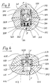
- FIGS. 1 and 2 show the basic operating principles of the positioning device according to the invention.
- the two components 1oo and 1o2 are to be centered with respect to an axis 104 which runs through the center of the ball 1o6.
- Each component 100, 102 is provided with a positioning plate 108 or 110 of different construction, each of which is inserted into a corresponding hole in the component concerned.
- the plate 108 is actually only a perforated disc, supported near its outer circumference by a shoulder of the component 100, while the plate 110 is cup-shaped with a central perforation in the base and is supported with the free edge of its edge.
- the ball 106 is pierced and a clearance screw 112 penetrates it with play, which can be screwed into the component 102 and presses with its head onto the opposite outer surface of the component 100.
- the ball diameter which can be defined by contact zones of the positioning recesses in the positioning plates when the joining surfaces 116, 118 abut when the ball is removed, has an undersize with respect to the ball 1o6, so that, as shown in FIG mutually opposite joining surfaces is present.
- the parts 106, 108 and 110 are elastically deformed, namely the ball 106 by compressive stresses and the plates 108 and 110 by compressive and - mainly - bending stresses, the division of the deformation components by the designer by appropriate choice of Dimensions can be made.
- the modulus of elasticity of the materials used also plays a role, as does the coefficient of friction acting between them and the profile of the positioning recesses and the selected contact area of the ball 106 (closer to its equator or closer to its poles). It has been shown that even with ball diameters of 60 mm, a repeat accuracy of the centering in the order of magnitude of 1 micron and smaller can be achieved without a disproportionately high clamping force having to be applied.
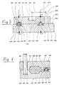
- FIGS. 3 and 4 show positioning devices which can be used in a very general way, for example in the field of mechanical engineering or device construction.
- the positioning devices have been realized through the interaction of standardized components.
- the ones carrying the positioning recesses 328, 418 and on their membrane-shaped parts in the axial direction deformable components are designed as press-in "positioning inserts".
- These standardized positioning inserts are provided with hardened and ground surfaces on the outside diameter and on the positioning recess and have a press-in phase on the outside cylinder.
- FIGS. 3 and 4 correspond to those in FIG. 2, ie the two components 300 and 302 to be positioned in a precise relative position are clamped together by a clamping force F on their joining surfaces 324 and 326 after a joining gap (similar to 114 in FIG 1) has been eliminated while deforming the plate-shaped part of the positioning inserts 304 or 404 (in FIG. 4).
- the depth of the positioning inserts 304 pressed into the bores 312 can be predetermined or changed by screw inserts 308.
- a hexagon socket 31o enables the generation of a screwing movement.
- the interference fit of the positioning insert 304 ensures a concentric fit of the positioning recess 328 relative to the component bore 312 due to the lack of play and at the same time ensures good transverse axial rigidity of the positioning insert.
- a threaded bolt 314 is welded on, which is in engagement with a nut 316 which is supported against disc springs 318. Falling out of the plate springs and nut is prevented by 2 locking rings 320, 322.
- the positioning insert 404 is seated with the plate-shaped component 420 having the positioning recess 418 on the bottom 408 of the component bore 410.
- the positioning element 406 has a spherical, but preferably spherical, shaped contact zone 416 protruding beyond the joining surface 324 and a cylindrical part 414 with which it is pressed into the receiving bore 412 of the component 302.
- a nozzle 426 is inserted, the inner bore of which is connected to a compressed air source, not shown.
- test air can be let in through the nozzle 426 in the now closed interior of bore 41o, in order to be able to conclude that the positioning process has been carried out correctly by means of the tightness to be tested.
- FIGS. 5 and 6 Special fields of application of the positioning devices described so far are shown in FIGS. 5 and 6.
- FIG. 5 shows an advantageous application of the positioning device according to the invention in connection with the positioning of workpieces on clamping bases.
- a component 502 to be machined is positioned relative to the clamping base 504 by means of two positioning devices 544, 546 and clamped with its clamping surface 548 under the action of clamping forces symbolized by arrows F against the mounting surface 550 of the clamping base.
- the central axes of the positioning devices brought into coincidence by means of the spherical positioning elements 528, 530 are identified by the lines 512, 526.
- Positioning inserts 524, 538 (similar to part 404 in FIG. 4), which form the actual positioning recesses 540, 542 with their central bores, are inserted on the left in the upper and in the lower part in the receiving bores 522, 536.
- R e CHTS is formed the positioning in the lower part of the locating insert 534 and molded directly into the component 502 in the upper part.
- the clamped component 502 could be any workpiece.
- the component 502 is one which belongs to the species of the standard parts, which are pre-processed to a certain extent by the standard parts manufacturer and which subsequently be reworked by the user to produce the final shape.
- Subsequent processing e.g.
- the production of a cylindrical recess 520 centered on the center axis 516 usually takes place by means of several successive work operations (e.g. milling, eroding, grinding) on different work machines.
- each operation requires a precise reference to the machining features created in the previous operation. It may also be necessary for the processing features to be created by the user into one exact reference to the dimensions already created by the manufacturer, e.g. hole 508.
- the positioning recesses 540, 518 already made by the manufacturer have the task in the course of further processing for the user to carry out an exact alignment of the component with each new work operation and to serve as a reference material measure for the dimensions to be produced during the operation.
- the clamping pad 504 can be different for each work operation and can always remain on the same processing machine.
- the measuring system of the processing machine is advantageously always brought into a precise dimensional reference to the clamping base, for which purpose e.g. the center axis of the positioning inserts 538, 534 can be used.
- the machine measuring system is thus automatically aligned precisely relative to component 502.
- the positioning recess 518 can be made directly in the component body.
- a spherical cap-shaped design of the contact zones is advantageous. Another possibility for saving costs is that the standard component 502 initially only has receiving bores 522 into which the positioning inserts 524 with the actual positioning recesses 540 are subsequently inserted (pressed in), the positioning inserts 524 being reusable several times.
- the clamping pad 504 will usually have a plurality of positioning recesses in order to accommodate components of different sizes.
- the center axes of the positioning recesses of the component and the mounting base preferably lie on the intersection of grid lines of a standard grid.
- FIG. 6 shows the use of a positioning device on an injection molding tool for extremely precise centering of the two mold halves 602 and 604.
- the positioning device 628 and the guide column 608 are only shown once in the drawing, although both are each present twice.
- the guide columns 608 are inserted with undersize in the guide bores 612. They take over the guiding of the upper mold half when opening the tool to eject the molded part 606 and also when closing the tool as a pre-centering for the positioning process which begins only in the last phase of the closing path by the positioning devices 628.
- the positioning devices 628 have positioning inserts 616 , 620, of which only part 616 has an axially deformable plate-shaped component.
- the forces symbolized by the arrows F can not only be generated manually by mechanically acting clamping elements, but can also be introduced magnetically, electromagnetically, hydraulically or by other means by means of negative pressure.
Landscapes
- Engineering & Computer Science (AREA)
- Mechanical Engineering (AREA)
- Manufacturing & Machinery (AREA)
- Jigs For Machine Tools (AREA)
- Multi-Conductor Connections (AREA)
- Connection Of Plates (AREA)
Abstract
Description
Die Erfindung betrifft eine Positioniereinrichtung zum Fügen zweier Bauteile in vorgegebener Relativlage mit den im Oberbegriff des Patentanspruchs 1 genannten Merkmalen. Eine solche Vorrichtung ist aus der Druckschrift EP-A-111 092 bekannt. Dort ist ein sich verjüngendes Positionierelement vorgesehen, das beim Fügen in eine aus einerMembran ausgenommene Positionierausnehmung eindringt. Die Membran ist im Abstand von der Positionierausnehmung auf einem Bund abgestützt und mittels Schrauben an dem zweiten Bauteil befestigt.The invention relates to a positioning device for joining two components in a predetermined relative position with the features mentioned in the preamble of claim 1. Such a device is known from EP-A-111 092. There is a tapered positioning element which, when joined, penetrates into a positioning recess recessed from a membrane. The membrane is supported on a collar at a distance from the positioning recess and fastened to the second component by means of screws.
Aufgabe der Erfindung ist es, eine Positioniereinrichtung gleicher Gattung zu schaffen, bei der die Fügegenauigkeit trotz der beim Fügen in dem plattenartigen Träger entstehenden Spannungen auch bei oftmaliger Wiederholung des Fügevorgangs erhalten bleibt.The object of the invention is to provide a positioning device of the same type, in which the joining accuracy is maintained even when the joining process is repeated, despite the stresses that arise in the plate-like carrier during joining.
Die erfindungsgemäß zur Lösung dieser Aufgabe vorgesehenen Merkmale sind in dem kennzeichnenden Teil des Patentanspruchs 1 definiert. Die von dem unabhängigen Anspruch 1 abhängenden Ansprüche definieren bevorzugte Weiterbildungen dieser Konzeption.The features provided according to the invention for achieving this object are defined in the characterizing part of patent claim 1. The claims dependent on independent claim 1 define preferred developments of this concept.
Die Erfindung wird nachstehend im einzelnen unter Bezugnahme auf die beigefügten Zeichnungen näher erläutert.
- Fig. 1
- zeigt eine Positioniereinrichtung gemäß der Erfindung vor dem Zusammenspannen der beiden Bauteile im Axialschnitt,
- Fig. 2
- zeigt die Einrichtung nach Fig. 1 nach dem Fügen und Spannen,
- Fig. 3
- zeigt im Axialschnitt eine erfindungsgemäße Positioniereinrichtung in einer für eine universelle Verwendungsmöglichkeit geeigneten Ausgestaltung.
- Fig. 4
- zeigt eine andere Ausführung der Positioniereinrichtung mit nur einer axialverlagerbaren Positionierausnehmung.
- Fig. 5
- zeigt im Schnitt eine Baueinheit aus einer Aufspannunterlage mit aufgespanntem Werkstück, und
- Fig. 6
- zeigt im Schnitt eine Baueinheit aus zwei Werkzeughälften.
- Fig. 1
- shows a positioning device according to the invention before clamping the two components in axial section,
- Fig. 2
- shows the device of FIG. 1 after joining and tensioning,
- Fig. 3
- shows in axial section a positioning device according to the invention in a configuration suitable for universal use.
- Fig. 4
- shows another embodiment of the positioning device with only one axially displaceable positioning recess.
- Fig. 5
- shows in section a unit from a clamping base with a clamped workpiece, and
- Fig. 6
- shows in section a unit from two tool halves.
Die grundsätzlichen Wirkprinzipien der erfindungsgemäßen Positioniereinrichtung werden in Fig. 1 und 2 verdeutlicht, von denen Fig. 1 die Situation vor dem Zusam - menspannen darstellt und Fig. 2 die Situation nach dem Zusammenspannen.The basic operating principles of the positioning device according to the invention are illustrated in FIGS. 1 and 2, of which FIG. 1 shows the situation before the clamping and FIG. 2 the situation after the clamping.
In der Ausführungsform nach Fig. 1 und 2 sind die beiden Bauteile 1oo und 1o2 bezüglich einer Achse 104 zuzentrieren, die durch den Mittelpunkt der Kugel 1o6 verläuft. Jedes Bauteil 100, 102 ist mit einer Positionierplatte 108 bzw. 110 von unterschiedlicher Konstruktion versehen, die jeweils in eine entsprechende Bohrung des betreffenden Bauteils eingefügt ist. Die Platte 108 ist tatsächlich nur eine gelochte Scheibe, nahe ihrem Außemumfang durch eine Schulter des Bauteils 100 abgestützt, wahrend die Platte 110 topfförmig mit einer zentralen Lochung des Bodens ist und sich mit der freien Kante ihres Randes abstützt. Die Kugel 106 ist durchbohrt und mit Spiel von einer Spannschraube 112 durchsetzt, die in das Bauteil 102 einschraubbar ist und mit ihrem Kopf auf die gegenüberliegende Außenfläche des Bauteils 100 drückt.In the embodiment according to FIGS. 1 and 2, the two components 1oo and 1o2 are to be centered with respect to an
Der durch Kontaktzonen der Positionierausnehmungen in den Positionierplatten beim Anliegen der Fügeflächen 116, 118 bei entfernter Kugel definierbare Kugel-Durchmesser hat ein Untermaß bezüglich der Kugel 1o6, so daß vor dem Anziehen der Schraube, wie in Fig. 1 dargestellt, ein Spalt 114 zwischen den einander gegenüberliegenden Fügeflächen vorhanden ist. Beim Zusammenspannen mittels der Schraube werden die Teile 106, 108 und 110 elastisch deformiert, nämlich die Kugel 106 durch Druckspannungen und die Platten 108 und 110 durch Druck- und -- hauptsächlich -- Biegespannungen, wobei die Aufteilung der Deformationskomponenten vom Konstrukteur durch entsprechende Wahl der Abmessungen vorgenommen werden kann. Dabei spielt natürlich auch der Elastizitätsmodul der verwendeten Materialien eine Rolle wie auch der zwischen Ihnen wirkende Reibungskoeffizient und das Profil der Positionierausnehmungen und der ausgewählte Kontaktbereich der Kugel 106 (näher an ihrem Äquator oder näher an ihren Polen). Es hat sich gezeigt, daß selbst bei Kugel-Durchmessern von 60 mm eine Wiederholgenauigkeit der Zentrierung in der Größenordnung von 1 Mikron und kleiner er - reichbar ist, ohne daß eine unverhältnismäßig hohe Spannkraft aufzubringen wäre.The ball diameter, which can be defined by contact zones of the positioning recesses in the positioning plates when the
In den Figuren 3 und 4 werden Positioniereinrichtungen gezeigt, die ganz allgemein verwendbar sind, z.B. im Bereich des Maschinenbaues oder des Vorrichtungsbaues. Dabei sind die Positioniereinrichtungen durch das Zusammenwirken von standardisierten Bauelementen realisiert worden. Die die Positionierausnehmungen 328, 418 tragenden und an ihren membramförmigen Partien in Axialrichtung verformbaren Bauelemente sind als einpreßbare "Positioniereinsätze" ausgebildet. Diese standardisierten Positioniereinsätze sind mit gehärteten und geschliffenen Flächen am Außendurchmesser und an der Positionierausnehmung versehen und weisen am Außenzylinder eine Einpreßphase auf.FIGS. 3 and 4 show positioning devices which can be used in a very general way, for example in the field of mechanical engineering or device construction. The positioning devices have been realized through the interaction of standardized components. The ones carrying the
Die in Figur 3 und 4 dargestellten Situationen entsprechen der der Figur 2, d.h., die beiden in eine genaue Relativlage zu positionierenden Bauteile 300 und 302 sind durch eine Spannkraft F an ihren Fügeflächen 324 und 326 zusammengespannt, nachdem zuvor ein Fügespalt (ähnlich 114 in Fig. 1) unter Deformation des plattenförmigen Teiles der Positioniereinsätze 304 bzw. 404 (in Fig. 4) beseitigt worden ist.The situations shown in FIGS. 3 and 4 correspond to those in FIG. 2, ie the two
In Figur 3 kann die Tiefe der in den Bohrungen 312 eingepreßten Positioniereinsätze 304 durch Schraubeinsätze 308 vorbestimmt bzw. verändert werden. Ein Innensechskant 31o ermöglicht die Erzeugung einer Schraubbewegung.In FIG. 3, the depth of the
Der Preßsitz des Positioniereinsatzes 304 sichert durch Spielfreiheit einen konzentrischen Sitz der Positionierausnehmung 328 relativ zur Bauteilebohrung 312 und gewährleistet gleichzeitig eine gute queraxiale Steifigkeit des Positioniereinsatzes.The interference fit of the
Um die als Positionierelement dienende Kugel 306 unverlierbar zu machen, ist ein Gewindebolzen 314 angeschweißt, welcher im Eingriff mit einer sich gegen Tellerfedern 318 abstützenden Mutter 316 steht. Ein Herausfallen von Tellerfedern und Mutter wird durch 2 Sicherungsringe 320, 322 verhindert.In order to make the
In Figur 4 sitzt der Positioniereinsatz 404 mit dem die Positionierausnehmung 418 aufweisenden plattenförmigen Bestandteil 420 auf dem Boden 408 der Bauteilbohrung 410 auf.In FIG. 4, the
Das Positionierelement 406 verfügt in diesem Falle über eine über die Fügefläche 324 vorstehende sphärisch, vorzugsweise jedoch kugelförmig, geformte Kontaktzone 416 und über einen zylindrischen Teil 414, mit dem es in der Aufnahmebohrung 412 des Bauteiles 302 eingepreßt ist.In this case, the
Im Bauteil 300 ist eine Düse 426 eingesetzt, deren Innenbohrung mit einer nicht dargestellten Druckluftquelle verbunden ist.In the
Beim Annähern der beiden Fügeflächen 324, 326 während des Fügevorganges ist zwischen der Kontaktzone 416 und der Positionierausnehmung 418 ein Ringspalt vorhanden. Ein durch die Düse 426 während des Fügevorganges hindurchtretender Luftstrahl wandelt sich beim Auftreffen auf die Kontaktzone 416 in einen zur Mittenachse rotationssymmetrischen Luftfilm (was durch die Pfeile 424 angedeutet ist), welcher an der Oberfläche der Kontaktzone 416 etwaig vorhandene Schmutzpartikel wegbläst.When the two joining
Nach Durchführung des Fügevorganges kann in den nun verschlossenen Innenraum von Bohrung 41o Prüfluft durch die Düse 426 eingelassen werden, um über die zu prüfende Dichtigkeit auf einen korrekt durchgeführten Positioniervorgang schließen zu können.After the joining process has been carried out, test air can be let in through the
Spezielle Einsatzgebiete der bisher beschriebenen Positioniereinrichtungen werden in den Figuren 5 und 6 gezeigt.Special fields of application of the positioning devices described so far are shown in FIGS. 5 and 6.
In Figur 5 wird eine vorteilhafte Anwendung der erfinderischen Positioniereinrichtung im Zusammenhang mit der Positionierung von Werkstücken auf Aufspannunterlagen gezeigt.FIG. 5 shows an advantageous application of the positioning device according to the invention in connection with the positioning of workpieces on clamping bases.
Ein zu bearbeitendes Bauteil 502 ist mittels zweier Positioniereinrichtungen 544, 546 relativ zur Aufspannunterlage 504 positioniert und mit seiner Aufspannfläche 548 unter der Einwirkung von durch Pfeile F symbolisierten Spannkräften gegen die Aufnahmefläche 550 der Aufspannunterlage verspannt.A
Die mittels der kugelförmigen Positionierelemente 528, 530 in koinzidenz gebrachten Mittenachsen der Positioniereinrichtungen sind durch die Linien 512, 526 gekennzeichnet.The central axes of the positioning devices brought into coincidence by means of the
Zur Veranschaulichung der Variationsmöglichkeit sind die beiden Positioniereinrichtungen aus unterschiedlichen Bauelementen zusammengesetzt dargestellt. Links sind im oberen, wie im unteren Teil in den Aufnahmebohrungen 522, 536 Positioniereinsätze 524, 538 eingesetzt (ähnlich Teil 404 in Fig. 4), die mit ihren zentrischen Bohrungen die eigentlichen Positionieraus - nehmungen 540, 542 bilden.To illustrate the possibility of variation, the two positioning devices are shown composed of different components. Positioning inserts 524, 538 (similar to
Rechts ist die Positionierausnehmung im unteren Teil an dem Positioniereinsatz 534 ausgebildet und im oberenTeil unmittelbar in das Bauteil 502 eingeformt.R e CHTS is formed the positioning in the lower part of the locating
Das aufgespannte Bauteil 502 könnte ein beliebiges Werkstück sein. Um einen besonderen Einsatzfall für die Positioniereinrichtung nach der Erfindung demonstrieren zu können, wird für Figur 5 angenommen, daß es sich bei dem Bauteil 502 um ein solches handelt, welches zur Spezies der Normalien gehört, welche vom Normalienhersteller in gewissem Umfang vorbearbeitet werden und welche nachfolgend von dem Anwender zur Herstellung der endgültigen Formgestaltung nachbearbeitet werden.The
Die Nachfolgebearbeitung, z.B. die Herstellung einer zur Mittenachse 516 zentrischen zylindrischen Ausnehmung 520 findet dabei in der Regel durch mehrereaufeinanderfolgende Arbeitsoperationen (z.B. Fräsen, Erodieren, Schleifen) auf unterschiedlichen Arbeitsmaschinen statt.Subsequent processing, e.g. The production of a
Wichtig bei der Durchführung der nacheinander folgenden Operationen ist, daß bei jeder Operation ein genauer Maßbezug zu den bei der vorangegangenen Operation geschaffenen Bearbeitungsmerkmalen hergestellt werden muß. Dabei kann es auch erforderlich sein, daß die vom Anwender zu schaffenden Bearbeitungsmerkmale in einen genauen Maßbezug zu bereits vom Hersteller geschaffenen Merkmalen, z.B. Bohrung 508 zu bringen sind.It is important when carrying out the successive operations that each operation requires a precise reference to the machining features created in the previous operation. It may also be necessary for the processing features to be created by the user into one exact reference to the dimensions already created by the manufacturer,
Den bereits vom Hersteller angebrachten Positionierausnehmungen 540, 518 kommt im Verlaufe der Weiterbearbeitung beim Anwender die Aufgabe zu, bei jeder neuen Arbeitsoperation eine genaue Ausrichtung des Bauteiles vorzunehmen und als Referenz-Maßverkörperung für die bei der Operation herzustellenden Maße zu dienen.The positioning recesses 540, 518 already made by the manufacturer have the task in the course of further processing for the user to carry out an exact alignment of the component with each new work operation and to serve as a reference material measure for the dimensions to be produced during the operation.
Bei jeder Arbeitsoperation kann die Aufspannunterlage 504 eine andere sein, die dabei auch stets auf ein und derselben Bearbeitungsmaschine verbleiben kann.The
Im letzteren Falle ist das Meßsystem der Bearbeitungsmaschine vorteilhafterweise stets in einen genauen Maßbezug zu der Aufspannunterlage gebracht, wozu z.B. die Mittenachse der Positioniereinsätze 538, 534 herangezogen werden können. Automatisch ist damit das Maschinen-Meßsystem auch genau relativ zum Bauteil 502 ausgerichtet.In the latter case, the measuring system of the processing machine is advantageously always brought into a precise dimensional reference to the clamping base, for which purpose e.g. the center axis of the positioning inserts 538, 534 can be used. The machine measuring system is thus automatically aligned precisely relative to
Mit dem beschriebenen Verfahren kann sowohl ein bedeutender Rationalisierungseffekt wie auch - bedingt durch die ultrapräzise Positioniergenauigkeit der Positioniereinrichtungen - eine beachtliche Steigerung der Genauigkeit der Lage der an den Bauteilen gefertigten Bearbeitungsmerkmale erzielt werden.With the described method, both a significant rationalization effect and - due to the ultra-precise positioning accuracy of the positioning devices - a considerable increase in the accuracy of the position of the machining features produced on the components can be achieved.
Während die an den Aufspannunterlagen angebrachten Einzelteile der Positioniereinrichtungen stets an der gleichen Stelle wieder verwendet werden können, ist dies für das Bauteil 502 nicht der Fall.While the individual parts of the positioning devices attached to the clamping pads can always be used again in the same place, this is not the case for
Zur Verringerung des Herstelleraufwandes für das Bauteil 502 kann die Positionierausnehmung 518 unmittelbar in den Bauteilkörper eingelassen sein.To reduce the manufacturing effort for the
Dabei ist eine Kugelkalotten-förmige Ausbildung der Kontaktzonen vorteilhaft. Eine weitere Möglichkeit zur Kosteneinsparung ist dadurch gegeben, daß das Normalien-Bauteil 502 zunächst nur Aufnahmebohrungen 522 aufweist, in die nachträglich noch die Positioniereinsätze 524 mit den eigentlichen Positionierausnehmungen 540 eingesetzt (eingepreßt) werden, wobei die Positioniereinsätze 524 mehrfach wiederverwendbar sind.A spherical cap-shaped design of the contact zones is advantageous. Another possibility for saving costs is that the
Am Bauteil 502 können auch mehr als 2 Positionierausnehmungen angebracht sein. Die Aufspannunterlage 504 wird in derRegel eine Vielzahl von Positionierausnehmungen aufweisen, um Bauteile unterschiedlicher Größe aufnehmen zu können.More than 2 positioning recesses can also be provided on
Vorzugsweise liegen die Mittenachsen der Positionierausnehmungen von Bauteil und Aufspannunterlage auf dem Kreuzungspunkt von Rasterlinien eines Normrasters.The center axes of the positioning recesses of the component and the mounting base preferably lie on the intersection of grid lines of a standard grid.
Figur 6 zeigt den Einsatz einer Positioniereinrichtung an einem Spritzgußwerkzeug zur extrem genauen Zentrierung der beiden Formhälften 602 und 604. Die Positioniereinrichtung 628 und die Führungssäule 608 sind zeichnerisch nur einmal dargestellt, obwohl beide jeweils zweimal vorhanden sind. Die Führungssäulen 608 sind mit Untermaß in den Führungsbohrungen 612 eingesetzt. Sie übernehmen die Führung der oberen Formhälfte beim Öffnen des Werkzeuges zum Ausstoßen des Spritzteiles 606 sowie auch beim Schließen des Werkzeuge als Vorzentrierung für den erst in der letzten Phase des Schließweges einsetzenden Positioniervorgang durch die Positioniereinrichtungen 628. Die Positioniereinrichtungen 628 verfügen im gezeigten Beispiel über Positioniereinsätze 616, 620, wovon lediglich das Teil 616 über einen axialverformbaren plattenförmigen Bestandteil verfügt.FIG. 6 shows the use of a positioning device on an injection molding tool for extremely precise centering of the two
Die durch die Pfeile F symbolisierten Kräfte können nicht nur durch mechanisch wirkende Spannelemente von Hand erzeugt werden, sondern durch Unterdruck magnetisch, elektromagnetisch hydraulisch oder durch andere Mittel eingeleitet werden.The forces symbolized by the arrows F can not only be generated manually by mechanically acting clamping elements, but can also be introduced magnetically, electromagnetically, hydraulically or by other means by means of negative pressure.
Claims (7)
- Positioning device for joining two components in a prescribed relative position, having the features:(a) a first component (102, 302) has a projecting positioning member (106, 416) centrally symmetrical in relation to an axis (104, 428) and tapering outwards with a spherical curvature in the region of contact zones (430),b) a second component (100, 300) has a positioning recess (418) centrally symmetrical in relation to an axis (104, 428) and tapering inwards in the region of contact zones (432), and is capable of being joined to the first component in such a manner that the axes of both of them coincide,(c) both components have joint surfaces (116, 118, 326, 324) facing one another, which, after assembly, lie one against the other, the positioning member and the positioning recess having dimensions such that the joining operation takes place as defined in features (d) and (e) below,(d) during assembly the positioning member penetrates into the positioning recess in a first joining phase, until the contact zones provided for centering of the two components come into contact with one another, while a joint gap (114) still exists between the joint surfaces,(e) in a second joining phase the joint gap is closed through the action of an axial tension force, the material in the region of the contact zones being subjected to elastic deformation, the elastic deformation being predominantly a bending deformation with displacement of material substantially in the axial direction,(f) the positioning member and/or the positioning recess are provided on a plate-like carrier (108, 420) which is axially supported only near its outside contour and with its central region is resilient in the axial direction, characterised in that the plate-like carrier (108, 420) is in the form of the bottom of a pot (110, 404) inserted into a bore in the component.
- Positioning device according to Claim 1, characterised in that both components have positioning recesses (418, 412), between which the positioning member (106, 416) is disposed.
- Positioning device according to Claim 1, characterised in that the plate-like carrier (108, 420) is inserted into the respective component with an interference fit in the direction of the transverse axis.
- Positioning device according to one of Claims 1 to 3, characterised in that the positioning member (416) is spherical in shape at least on one side, at least in the region of its contact with the positioning recess (418).
- Positioning device according to Claim 4, characterised in that the positioning member (306) is a ball.
- Positioning device according to one of Claims 3 to 5, characterised in that the positioning member (306) has an extension (314), projecting into one of the components, for self-locking fastening.
- Positioning device according to one of Claims 1 to 6, characterised in that two or more positioning devices (544, 546) are provided for positioning two components (502, 504).
Priority Applications (1)
| Application Number | Priority Date | Filing Date | Title |
|---|---|---|---|
| AT88905376T ATE89210T1 (en) | 1987-06-23 | 1988-06-21 | POSITIONING DEVICE AND THEIR USE. |
Applications Claiming Priority (6)
| Application Number | Priority Date | Filing Date | Title |
|---|---|---|---|
| DE3720604 | 1987-06-23 | ||
| DE3720604 | 1987-06-23 | ||
| DE3722308 | 1987-07-07 | ||
| DE3722309 | 1987-07-07 | ||
| DE3722308 | 1987-07-07 | ||
| DE3722309 | 1987-07-07 |
Publications (2)
| Publication Number | Publication Date |
|---|---|
| EP0365557A1 EP0365557A1 (en) | 1990-05-02 |
| EP0365557B1 true EP0365557B1 (en) | 1993-05-12 |
Family
ID=27196129
Family Applications (1)
| Application Number | Title | Priority Date | Filing Date |
|---|---|---|---|
| EP88905376A Expired - Lifetime EP0365557B1 (en) | 1987-06-23 | 1988-06-21 | Positioning device and its use |
Country Status (6)
| Country | Link |
|---|---|
| US (1) | US5397231A (en) |
| EP (1) | EP0365557B1 (en) |
| JP (1) | JPH02503887A (en) |
| KR (1) | KR970005613B1 (en) |
| DE (1) | DE3881050D1 (en) |
| WO (1) | WO1988010172A1 (en) |
Families Citing this family (17)
| Publication number | Priority date | Publication date | Assignee | Title |
|---|---|---|---|---|
| DE3831736C2 (en) * | 1988-09-17 | 1998-11-26 | Gedib Ingbuero Innovation | Positioning device of two components in a predetermined relative position and their use |
| DE4203853C2 (en) * | 1992-02-11 | 1993-11-25 | Guenter Meywald | Positioning device for two components to be joined |
| DE4428310A1 (en) * | 1994-08-10 | 1996-02-15 | Manfred Schanz | Fastening device for a tool or workpiece |
| DE59705344D1 (en) * | 1996-06-17 | 2001-12-20 | Certa Ag Reinach | Clamping device and device for position-defined clamping of a tool or workpiece |
| US6050160A (en) * | 1996-09-04 | 2000-04-18 | Joseph B. Willey | Apparatus and method for automatically compensating for lateral runout |
| US6101911A (en) * | 1996-09-04 | 2000-08-15 | Joseph B. Willey | Apparatus and method for automatically compensating for lateral runout |
| EP0922529B1 (en) * | 1997-12-11 | 2002-11-06 | Parotec AG | Unit for releasable connection of parts of a palletising device and a palletising device itself |
| US6367765B1 (en) * | 1999-09-09 | 2002-04-09 | Klaus A. Wieder | Mold vent |
| US6558145B2 (en) * | 2000-07-06 | 2003-05-06 | Klaus A. Wieder | Mold interlock |
| EP1211021B1 (en) * | 2000-11-02 | 2006-07-19 | IEMCA Giuliani Macchine Italia S.p.A. | A transfer type machine tool |
| DE60208161T2 (en) * | 2002-05-21 | 2006-08-24 | Michel Yerly | Coupling for releasably connecting two components, and device with this coupling for presetting the tools of a machine tool |
| US7536935B2 (en) * | 2005-04-07 | 2009-05-26 | Pro-Cut Licensing Company, Llc | Brake rotor resurfacing |
| KR100726227B1 (en) * | 2006-07-03 | 2007-06-08 | 현대자동차주식회사 | Reference plane setting device for parts processing |
| CN101125726B (en) * | 2006-08-16 | 2011-05-04 | 鸿富锦精密工业(深圳)有限公司 | Molding die |
| SE538609C2 (en) * | 2015-01-20 | 2016-10-04 | Sundström Erik | Device for detachable and repeatable positioning of two objects in relation to each other |
| CN106273291A (en) * | 2015-05-20 | 2017-01-04 | 鸿富锦精密工业(深圳)有限公司 | Shutter device and there is the mould of this shutter device |
| SE544647C2 (en) * | 2020-10-21 | 2022-10-04 | Zerofix Tooling Ab | Positioning device for a positioning system |
Family Cites Families (15)
| Publication number | Priority date | Publication date | Assignee | Title |
|---|---|---|---|---|
| DE885951C (en) * | 1941-11-18 | 1953-08-10 | Ernst Hauer & Co | Multiple steel holder |
| US2908195A (en) * | 1958-01-20 | 1959-10-13 | Enco Mfg Co | Turret toolpost |
| CH515379A (en) * | 1969-01-27 | 1971-12-31 | Ciba Geigy Ag | Use of aqueous emulsions to make textile materials permanently water-repellent |
| US3723927A (en) * | 1969-05-05 | 1973-03-27 | Gen Dynamics Corp | Magnetic holding means in a surface plate dimensional measuring apparatus |
| DE2537146C3 (en) * | 1975-08-21 | 1980-05-14 | Hubert Dipl.-Ing. 5820 Gevelsberg Bald | Unit of two components to be positioned in a relative position |
| CH624329A5 (en) * | 1977-11-08 | 1981-07-31 | Bald Hubert | Method of clamping a workpiece in order to machine or inspect it, and clamping body for carrying out the method |
| DE3035229A1 (en) * | 1980-09-18 | 1982-04-29 | Dieter Hansen GmbH, 6116 Eppertshausen | ARRANGEMENT OF TOOL HOLDER AND SPINDLE CHUCK FOR MACHINE TOOLS AND COPYING METHOD FOR THE PRODUCTION |
| US4372738A (en) * | 1981-10-27 | 1983-02-08 | Pemco-Kalamazoo, Inc. | Collet lock for a mold assembly |
| US4512068A (en) * | 1982-08-23 | 1985-04-23 | Cincinnati Milacron Inc. | Pallet receiver with compliant pin and socket registration |
| DE3371676D1 (en) * | 1982-10-18 | 1987-06-25 | Erowa Ag | Coupling device |
| DE3436182C1 (en) * | 1984-10-03 | 1985-11-14 | Karl 7298 Loßburg Hehl | Injection mold for plastic injection molding machine with locking device |
| US4561626A (en) * | 1984-10-25 | 1985-12-31 | Pemco-Kalamazoo, Inc. | Mold opening device |
| US4855558A (en) * | 1986-07-29 | 1989-08-08 | System 3R International Ab | Clamping device for a tool at a machine tool, particularly at a die sinking electric discharge machine |
| DE3625608A1 (en) * | 1986-07-29 | 1988-04-21 | 3R Management Ab | Clamping device for a tool on a machine tool, in particular a cavity sinking EDM machine |
| DE3933348A1 (en) * | 1989-10-06 | 1991-04-18 | Kloeckner Ferromatik Desma | MOLDING LOCKING DEVICE FOR AN INJECTION MOLDING MACHINE |
-
1987
- 1987-06-23 US US08/101,264 patent/US5397231A/en not_active Expired - Fee Related
-
1988
- 1988-06-21 EP EP88905376A patent/EP0365557B1/en not_active Expired - Lifetime
- 1988-06-21 KR KR1019890700327A patent/KR970005613B1/en active IP Right Grant
- 1988-06-21 WO PCT/EP1988/000546 patent/WO1988010172A1/en active IP Right Grant
- 1988-06-21 JP JP63505065A patent/JPH02503887A/en active Pending
- 1988-06-21 DE DE8888905376T patent/DE3881050D1/en not_active Expired - Fee Related
Also Published As
| Publication number | Publication date |
|---|---|
| KR970005613B1 (en) | 1997-04-18 |
| WO1988010172A1 (en) | 1988-12-29 |
| DE3881050D1 (en) | 1993-06-17 |
| EP0365557A1 (en) | 1990-05-02 |
| US5397231A (en) | 1995-03-14 |
| KR890701281A (en) | 1989-12-19 |
| JPH02503887A (en) | 1990-11-15 |
Similar Documents
| Publication | Publication Date | Title |
|---|---|---|
| EP0365557B1 (en) | Positioning device and its use | |
| EP1268123B1 (en) | Device for the detachable mounting of workpieces on machining devices | |
| EP0818270B1 (en) | Clamping device and device for clamping a workpiece or tool in a precise position | |
| EP0753368B1 (en) | Clamping device for precise relative fixation of two pieces | |
| DE202013005616U1 (en) | Positioning device for workpiece holding device | |
| DE19858159C2 (en) | coupling device | |
| DE10135233B4 (en) | ring machine | |
| EP2101948B1 (en) | Device and method for positioning a tool or workpiece on a machine tool | |
| DE4203853A1 (en) | POSITIONING DEVICE FOR TWO COMPONENTS TO BE JOINED | |
| DE3901254C2 (en) | ||
| DE3708363A1 (en) | CHUCK FOR MACHINE TOOLS | |
| DE4005938C2 (en) | ||
| DE3302432A1 (en) | Machine bed, in particular of a machine tool, with a slide way consisting of micro-finished steel beams of prismatic cross-section, and a method for aligning and fixing the steel beam on the machine bed | |
| DE19756215C2 (en) | Quick-fit system for components of machine tools | |
| DE3439040A1 (en) | Device for connecting a toolholder to a toolholder fixture | |
| DE19860013C2 (en) | Device for clamping a sealing ring on a machine tool | |
| EP0900628B1 (en) | Quick fitting system | |
| DE4416262C1 (en) | Apparatus for fastening a blow pin of a hollow-article blow-moulding machine | |
| DE3820870A1 (en) | Device for centring an interchangeable pallet with regard to a clamping-fixture axis and positioning device intended for this | |
| DE19514512C2 (en) | Device for position-specific clamping of a workpiece | |
| DD283096A5 (en) | CLAMPING SYSTEM FOR INTERCHANGEABLE TOOLING TOOLS | |
| DE19705687C2 (en) | Process for the high-precision production of workpiece plates, in particular for the high-precision machining of the front and back of workpiece plates | |
| DD280061A1 (en) | CLAMPING SYSTEM FOR INTERCHANGEABLE TOOLING TOOLS | |
| DE3420660A1 (en) | Centring body for mounting a multi-part centring and clamp-screw device of bolt-like design | |
| DD288785A5 (en) | POSITIONING ELEMENT FOR ACCURATE POSITIONING OF WORKPIECES IN DEVICES |
Legal Events
| Date | Code | Title | Description |
|---|---|---|---|
| PUAI | Public reference made under article 153(3) epc to a published international application that has entered the european phase |
Free format text: ORIGINAL CODE: 0009012 |
|
| 17P | Request for examination filed |
Effective date: 19891123 |
|
| AK | Designated contracting states |
Kind code of ref document: A1 Designated state(s): AT BE CH DE FR GB IT LI NL SE |
|
| 17Q | First examination report despatched |
Effective date: 19910722 |
|
| GRAA | (expected) grant |
Free format text: ORIGINAL CODE: 0009210 |
|
| AK | Designated contracting states |
Kind code of ref document: B1 Designated state(s): AT BE CH DE FR GB IT LI NL SE |
|
| REF | Corresponds to: |
Ref document number: 89210 Country of ref document: AT Date of ref document: 19930515 Kind code of ref document: T |
|
| ITF | It: translation for a ep patent filed | ||
| REF | Corresponds to: |
Ref document number: 3881050 Country of ref document: DE Date of ref document: 19930617 |
|
| GBT | Gb: translation of ep patent filed (gb section 77(6)(a)/1977) |
Effective date: 19930526 |
|
| ET | Fr: translation filed | ||
| EAL | Se: european patent in force in sweden |
Ref document number: 88905376.5 |
|
| PGFP | Annual fee paid to national office [announced via postgrant information from national office to epo] |
Ref country code: GB Payment date: 19960516 Year of fee payment: 9 |
|
| PGFP | Annual fee paid to national office [announced via postgrant information from national office to epo] |
Ref country code: FR Payment date: 19960521 Year of fee payment: 9 |
|
| PGFP | Annual fee paid to national office [announced via postgrant information from national office to epo] |
Ref country code: SE Payment date: 19960523 Year of fee payment: 9 Ref country code: AT Payment date: 19960523 Year of fee payment: 9 |
|
| PGFP | Annual fee paid to national office [announced via postgrant information from national office to epo] |
Ref country code: CH Payment date: 19960524 Year of fee payment: 9 Ref country code: BE Payment date: 19960524 Year of fee payment: 9 |
|
| PGFP | Annual fee paid to national office [announced via postgrant information from national office to epo] |
Ref country code: NL Payment date: 19960630 Year of fee payment: 9 |
|
| PG25 | Lapsed in a contracting state [announced via postgrant information from national office to epo] |
Ref country code: GB Free format text: LAPSE BECAUSE OF NON-PAYMENT OF DUE FEES Effective date: 19970621 Ref country code: AT Effective date: 19970621 |
|
| PG25 | Lapsed in a contracting state [announced via postgrant information from national office to epo] |
Ref country code: SE Effective date: 19970622 |
|
| PG25 | Lapsed in a contracting state [announced via postgrant information from national office to epo] |
Ref country code: LI Free format text: LAPSE BECAUSE OF NON-PAYMENT OF DUE FEES Effective date: 19970630 Ref country code: CH Free format text: LAPSE BECAUSE OF NON-PAYMENT OF DUE FEES Effective date: 19970630 Ref country code: BE Effective date: 19970630 |
|
| BERE | Be: lapsed |
Owner name: GEDIB INGENIEURBURO UND INNOVATIONSBERATUNG G.M.B Effective date: 19970630 |
|
| PG25 | Lapsed in a contracting state [announced via postgrant information from national office to epo] |
Ref country code: NL Effective date: 19980101 |
|
| GBPC | Gb: european patent ceased through non-payment of renewal fee |
Effective date: 19970621 |
|
| REG | Reference to a national code |
Ref country code: CH Ref legal event code: PL |
|
| PG25 | Lapsed in a contracting state [announced via postgrant information from national office to epo] |
Ref country code: FR Free format text: LAPSE BECAUSE OF NON-PAYMENT OF DUE FEES Effective date: 19980227 |
|
| EUG | Se: european patent has lapsed |
Ref document number: 88905376.5 |
|
| NLV4 | Nl: lapsed or anulled due to non-payment of the annual fee |
Effective date: 19980101 |
|
| REG | Reference to a national code |
Ref country code: FR Ref legal event code: ST |
|
| REG | Reference to a national code |
Ref country code: FR Ref legal event code: ST |
|
| PGFP | Annual fee paid to national office [announced via postgrant information from national office to epo] |
Ref country code: DE Payment date: 20000823 Year of fee payment: 13 |
|
| PG25 | Lapsed in a contracting state [announced via postgrant information from national office to epo] |
Ref country code: DE Free format text: LAPSE BECAUSE OF NON-PAYMENT OF DUE FEES Effective date: 20020403 |
|
| PG25 | Lapsed in a contracting state [announced via postgrant information from national office to epo] |
Ref country code: IT Free format text: LAPSE BECAUSE OF NON-PAYMENT OF DUE FEES;WARNING: LAPSES OF ITALIAN PATENTS WITH EFFECTIVE DATE BEFORE 2007 MAY HAVE OCCURRED AT ANY TIME BEFORE 2007. THE CORRECT EFFECTIVE DATE MAY BE DIFFERENT FROM THE ONE RECORDED. Effective date: 20050621 |
|
| PLBE | No opposition filed within time limit |
Free format text: ORIGINAL CODE: 0009261 |
|
| STAA | Information on the status of an ep patent application or granted ep patent |
Free format text: STATUS: NO OPPOSITION FILED WITHIN TIME LIMIT |