EP0365345B1 - A corona wire cleaning device for a corona unit - Google Patents
A corona wire cleaning device for a corona unit Download PDFInfo
- Publication number
- EP0365345B1 EP0365345B1 EP89310809A EP89310809A EP0365345B1 EP 0365345 B1 EP0365345 B1 EP 0365345B1 EP 89310809 A EP89310809 A EP 89310809A EP 89310809 A EP89310809 A EP 89310809A EP 0365345 B1 EP0365345 B1 EP 0365345B1
- Authority
- EP
- European Patent Office
- Prior art keywords
- wire
- cleaning
- corona
- driving
- movement
- Prior art date
- Legal status (The legal status is an assumption and is not a legal conclusion. Google has not performed a legal analysis and makes no representation as to the accuracy of the status listed.)
- Expired - Lifetime
Links
Images


Classifications
-
- G—PHYSICS
- G03—PHOTOGRAPHY; CINEMATOGRAPHY; ANALOGOUS TECHNIQUES USING WAVES OTHER THAN OPTICAL WAVES; ELECTROGRAPHY; HOLOGRAPHY
- G03G—ELECTROGRAPHY; ELECTROPHOTOGRAPHY; MAGNETOGRAPHY
- G03G15/00—Apparatus for electrographic processes using a charge pattern
- G03G15/02—Apparatus for electrographic processes using a charge pattern for laying down a uniform charge, e.g. for sensitising; Corona discharge devices
- G03G15/0258—Apparatus for electrographic processes using a charge pattern for laying down a uniform charge, e.g. for sensitising; Corona discharge devices provided with means for the maintenance of the charging apparatus, e.g. cleaning devices, ozone removing devices G03G15/0225, G03G15/0291 takes precedence
-
- G—PHYSICS
- G03—PHOTOGRAPHY; CINEMATOGRAPHY; ANALOGOUS TECHNIQUES USING WAVES OTHER THAN OPTICAL WAVES; ELECTROGRAPHY; HOLOGRAPHY
- G03G—ELECTROGRAPHY; ELECTROPHOTOGRAPHY; MAGNETOGRAPHY
- G03G15/00—Apparatus for electrographic processes using a charge pattern
- G03G15/02—Apparatus for electrographic processes using a charge pattern for laying down a uniform charge, e.g. for sensitising; Corona discharge devices
- G03G15/0291—Apparatus for electrographic processes using a charge pattern for laying down a uniform charge, e.g. for sensitising; Corona discharge devices corona discharge devices, e.g. wires, pointed electrodes, means for cleaning the corona discharge device
Definitions
- the present invention relates to a corona wire cleaning device for a corona unit used, for example, as a charge unit, a transfer/separation unit, or the like, in an electrophotographic copying machine.
- a corona unit is used as a charge unit for uniformly charging the photoconductor.
- the corona unit includes a corona wire formed of tungsten, platinum, etc., stretched in a box-like shield case.
- gaseous silicon compounds such as silanes that are contained in the air surrounding the corona wire are converted into a silicon oxide compound which adheres to the surface of the corona wire.
- Adherence of the silicon oxide compound substantially impairs the discharging performance of the corona wire. Furthermore, for the corona unit used as a charge unit in an electrophotographic copying machine, adherence of paper dust and toner to the corona wire is also a problem since it reduces the discharging performance of the corona wire. If the discharging performance of the corona wire of the corona unit used as a charge unit is reduced, the photoconductor may not be charged uniformly, resulting in an uneven surface potential of the photoconductor and therefore, hampering formation of a clear image.
- JP-62/86375 discloses an automatic cleaning device for a corona unit which is used as a charge unit.
- a cleaning tool which rubs the corona wire
- a driving motor via a driving wire, forward and reverse rotation of the driving motor driving the driving wire to move the cleaning tool respectively in the forwards and backwards directions along the corona wire.
- the driving wire is moved backwards and forwards, the cleaning tool rubs the corona wire to clean it.
- a sensor disposed in close proximity to the end is activated to stop the rotation of the driving motor.
- US-3 842 273 discloses a corona wire cleaning device in which a driving wire passed around two pulleys is caused to undergo reciprocating movement longitudinally so as to move a cleaning member forwards and backwards along a corona wire stretched in a shield case of a corona unit.
- the cleaning member has a support frame, which is slidable along the shield case, and a support lever which is pivotally attached to the support frame and carries a cleaning tool having opposite edges that rub against the corona wire respectively during the forwards and backwards movement therealong.
- the cleaning tools of these devices for corona units are in frictional contact with the corona wire in both directions of the cleaning operation, so that foreign material such as dust removed by the cleaning tool during the forwards movement will be carried back by the tool and re-applied to the corona wire during the backwards travel of the cleaning tool.
- a corona wire cleaning device for cleaning a corona wire stretched in a shield case of a corona unit, comprising: a cleaning member having a support frame, which is slidable along the shield case so as to be capable of movement along the corona wire, and having a support lever which is pivotally attached to the support frame and carries a cleaning tool that rubs against the corona wire during such movement; and means including a driving wire which passes around two pulleys and can be caused to undergo reciprocating movement longitudinally, for moving the cleaning member forwards and backwards along the length of the corona wire; characterised in that the said support lever is acted upon by the driving wire in the forwards direction of movement of the cleaning member so that the lever is held in an operative disposition causing the cleaning tool to rub against the corona wire during such movement, thereby cleaning that wire, whereas on backwards movement of the cleaning member the support lever pivots, relative to the support frame, to a non-operative disposition such that the cleaning
- An embodiment of the invention having the cleaning tool mounted at one end of the support lever, may have engaging means provided at the other end of the lever for engaging operating means provided on the driving wire to move the lever and the frame in accordance with movement of the operating means in either direction of movement of the driving wire, to pull the slide in the direction concerned.
- Such operating means may comprise two operating members attached to the driving wire and spaced apart so that in said one direction of movement one operating member acts on the frame and the other operating member acts on the lever engaging means, and in the other direction the other operating member acts on the frame and the said one operating member acts on the lever engaging means.
- the cleaning device may be provided with a pair of cleaning tools for simultaneously cleaning a pair of corona wires held taut in the shield case.
- Two slides may be provided for movement in opposite directions respectively for cleaning a pair of corona wires held taunt in the shield case.
- the cleaning device may then be such that, in one direction of movement of the driving wire, only the cleaning tool of one slide rubs and cleans the corona wire, the cleaning tool of the other slide being withdrawn from the corona wire.
- one of the said two pulleys is a driving pulley and the other an idler pulley
- means for limiting movement of the driving wire in at least one direction may be provided advantageously at a location near the idler pulley.
- the movement of the driving wire may be limited by abutment of a stop member, provided on the driving wire and moving in the same direction as the cleaning member, against a limiting member, and movement of the driving wire in the opposite direction may be limited by a stop member on the driving wire coming into abutment with another limiting member.
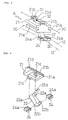
- Fig. 1 is a perspective view showing a corona unit having a corona wire cleaning device embodying the present invention.
- Fig. 2 is a perspective view showing a cleaning member of the cleaning device shown in Fig. 1.
- Fig. 3 is an exploded perspective view of the cleaning member of Fig. 2.
- Figs. 4a and 4b are a plan view and a side view showing a main part of the corona wire cleaning device of Fig. 1 to explain the operation thereof.
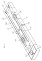
- Fig. 5 is a diagrammatic plan view showing the whole construction of the cleaning device of Fig. 1.
- Figs. 6a and 6b are a plan view and a side view showing a main part of the corona wire cleaning device of Fig. 1 to explain the operation thereof.
- Fig. 7 is a perspective view showing a corona unit having another corona wire cleaning device embodying the present invention.
- Fig. 8 is a diagrammatic plan view showing the operation of the cleaning device of Fig. 7.
- Figs. 1 to 6a and 6b show a corona unit 10 in which the corona wire cleaning device embodying the present invention is installed.
- the corona unit 10 is used, for example, as a charge unit in an electrophotographic copying machine.
- the corona unit 10 includes a shield case 11 having the shape of a rectangular parallelepiped, and a pair of parallel corona wires 12 and 12 stretched in the shield case 11 along the longitudinal length thereof.
- the shield case 11 has an open side (bottom), and an end block (not shown) is fitted to each end thereof.
- the ends of each corona wire 12 are fixed within the respective end blocks.
- Provided in the side (top) of the shield case 11 opposite the open side is an elongated opening 11a extending parallel to the corona wires 12 and 12 stretched in the shield case 11 .
- the corona wire cleaning device of the present invention comprises a cleaning member 20 which moves along the elongated opening 11a in the shield case 11 of the corona unit 10 , and a driving wire 30 which moves the cleaning member 20 along the elongated opening 11a .
- the driving wire 30 passes around an idler pulley 42 mounted, with a support plate 41 interposed, on the upper surface of one end of the shield case 11 , and is wound on a driving pulley 44 disposed in a motor box 43 connected to the other end of the shield case 11 .
- the driving wire 30 has two sections stretched parallel to each other between the driving pulley 44 and the idler pulley 42 , one section thereof being stretched above the elongated opening 11a of the shield case 11 .
- the driving pulley 44 is mounted on a pinion gear 45 disposed in the motor box 43 , and rotates integrally with the pinion gear 45 .
- the pinion gear 45 is engaged with a worm gear 46 which is connected to the output shaft of a driving motor 47 disposed in the motor box 43 .
- the driving motor 47 is capable of rotating in both forward and reverse directions.
- the idler pulley 42 around which the driving wire 30 passes at the other end of the shield case 11 is rotatably installed on the support plate 41 mounted slidably on the upper surface of the end of the shield case 11 .
- There are also disposed a pair of tension springs 48 and 48 one end of each being fixed to the support plate 41 and the other end to the upper surface of the end of the shield case 11 so as to exert force to pull the support plate 41 in the direction away from the driving pulley 44 . Therefore, the idler pulley 42 is always pulled by the pair of tension springs 48 and 48 via the support plate 41 in the direction away from the driving pulley 44 , and any variation in the tensile force applied to the driving wire 30 is absorbed by the tension springs 48 and 48 .
- the cleaning member 20 installed on the driving wire 30 includes, as shown in Figs. 2 and 3, a support frame 21 having the shape of a rectangular parallelepiped, and a support lever 22 swingably mounted on the support frame 21 .
- a guide groove 21a is formed on each of the sides of the support frame 21 that extend along the longitudinal length of the elongated opening 11a .
- the guide grooves 21a and 21a slidably engage the respective longitudinal edges of the elongated opening 11a of the shield case 11 .
- the upper surface of the support frame 21 is positioned above the shield case 11, and on each of the ends of the upper surface facing the respective moving directions of the support frame 21 there are provided engaging portions 21b and 21b projecting upwardly thereof.
- Each engaging portion 21b has a U-shaped form with an open side, through which the driving wire 30 passes.
- the support lever 22 bent in a dogleg form is disposed through the support frame 21.
- An upper end portion of the support lever 22 projects above the upper surface of the support frame 21, while a lower end portion thereof projects below the underside of the support frame 21 positioned inside the shield case 11.
- At the bend of the support lever 22 are provided a pair of support pins 22a and 22a projecting sideward as shown in Fig. 3.
- the support lever 22 is pivotally supported via the pair of support pins 22a and 22a by a pair of bearings 21c provided on the underside of the support frame 21, so that when the upper arm thereof is positioned approximately perpendicular with respect to the support frame 21, the lower arm is positioned to point toward the idler pulley 42.
- a vertically elongate cutout 22d through which the driving wire 30 passes.
- a pair of sideways projecting tenons 22b and 22b onto each of which a cleaning tool 24 is fitted.
- the cleaning tools 24 and 24 are positioned respectively adjacent to the corona wires 12 and are provided each with a cleaning part 24a on the upper surface thereof facing the corresponding corona wire 12 .
- the support lever 22 is bent so that its lower arm points toward the direction opposite from the driving pulley 44 , and when the upper arm of the support lever 22 is tilted toward the driving pulley 44 , the cleaning parts 24a and 24a of the cleaning tools 24 and 24 provided on the lower arm are caused to swing upward into contact with the respective corona wires 12 and 12 . Conversely, when the upper arm of the support lever 22 is tilted toward the idle pulley 42 , the cleaning parts 24a and 24a of the cleaning tools 24 and 24 are caused to swing downward, coming away from the respective corona wires 12 and 12 so that the cleaning member 20 is rendered inoperative.
- the driving wire 30 passing through the engaging portions 21b and 21b provided on the upper surface of the support frame 21 also passes through the cutout 22d in the upper end of the support lever 22 between the two engaging portions 21b and 21b .
- a spherically-shaped operating member 31 is provided on a portion of the driving wire 30 positioned between the engaging portion 21b nearer to the driving pulley 44 and the cutout 22d in the support lever 22
- another spherically-shaped operating member 32 is provided on a portion of the driving wire 30 positioned between the engaging portion 21b nearer to the idle pulley 42 and the cutout 22d in the support lever 22 .
- Both the operating members 31 and 32 have a larger size than that of the cutout 22d in the upper end of the support lever 22 so that they do not pass therethrough but stop at the support lever 22. Both the operating members 31 and 32 also are too large to pass through the engaging portions 21b and 21b, so that they stop at the respective engaging portions 21b and 21b.
- the operating members 31 and 32 work in the following way.
- the driving wire 30 is moved toward the driving pulley 44 (in the direction indicated by arrow A in Fig. 1)
- the operating member 32 positioned farther from the driving pulley 44 acts against the upper end portion of the support lever 22, urging the upper arm of the support lever 22 towards the driving pulley 44.
- the operating member 31 positioned nearer to the driving pulley 44 abuts against the engaging portion 21b that is nearer the driving pulley 44.
- the cleaning parts 24a and 24a on the cleaning tools 24 and 24 mounted on the lower arm of the support lever 22 are held in contact with the respective corona wires 12 and 12.
- a U-shaped limiting member 50 On the upper surface of the end of the shield case 11 where the idler pulley 42 is mounted, there is provided a U-shaped limiting member 50 having its open end uppermost.
- the section of the driving wire 30 stretched between the driving pulley 44 and the idler pulley 42 and not above the elongated opening lla of the shield case 11 passes through the limiting member 50.
- the limiting member 50 is positioned nearer to the idler pulley 42 than to the elongated opening lla provided in the upper surface of the shield case 11 .
- On the section of the driving wire 30 that passes through the limiting member 50 there is provided a spherically-shaped stop member 33 which can abut against the limiting member 50 .
- the stop member 33 is provided on the wire 30 at a fixed position such that it abuts against the limiting member 50 just before the cleaning member 20 being pulled by the driving wire 30 along the elongated opening 11a of the shield case 11 toward the driving pulley 44 reaches the end of the elongated opening 11a nearer to the driving pulley 44 .
- the corona wire cleaning device of the above construction works in the following manner.
- the cleaning member 20 is positioned at the end of the elongated opening 11a of the shield case 11 nearer to the idler pulley 42 , and in this situation, the driving motor 47 is started for forward rotation.
- the driving motor 47 is started for forward rotation.
- the section of the driving wire 30 above the elongated opening 11a is moved toward the driving pulley 44 , as shown in Figs. 4a and 4b .
- the operating time of the driving motor 47 is a slightly longer than that needed for the cleaning member 20 to travel the entire length of the elongated opening 11a of the shield case 11 .
- the entire cleaning member 20 moves in the elongated opening 11a of the shield case 11 till reaching the vicinity of the end of the elongated opening 11a nearer to the driving pulley 44 .
- the stop member 33 provided on the section of the driving wire 30 moving away from the driving pulley 44 toward the idler pulley 42 stops at the limiting member 50 provided on the end of the shield case 11 where the idler pulley 42 is mounted, just before the cleaning member 20 reaches the end of the elongated opening 11a nearer to the driving pulley 44 .
- the driving wire 30 is prevented from moving further although the driving motor 47 is still being driven for forward rotation.
- the portion of the driving wire 30 stretched via the idler pulley 42 from where it is stopped at the limiting member 50 to where it is wound on the driving pulley 44 (the portion indicated by L1 in Fig. 5) is pulled by the driving pulley 44 , and the tensile force being exerted by the forward rotation of the driving motor 47 is therefore applied to that portion of the driving wire 30 .
- the portion of the driving wire 30 subjected to the tensile force at this time is relatively long, for example in comparison with the portion thereof (indicated by L2 in Fig.
- the driving motor 47 is started for reverse rotation so that the section of the driving wire 30 above the elongated opening lla starts to move toward the idler pulley 42, as shown in Figs 6a and 6b.
- This causes the operating member 31 provided on the driving wire 30 at a position nearer to the driving pulley 44 to push the upper arm of the supporting lever 22 toward the idler pulley 42, which in turn causes the lower arm of the support lever 22 to swing downward with the cleaning parts 24a and 24a on the cleaning tools 24 and 24 mounted on the lower arm coming out of contact with corona wires 12 and 12.
- the operating member 32 nearer to the idler pulley 42 abuts the engaging portion 21b, formed on the support frame 21 of the cleaning member 20 at the end thereof nearer the idler pulley 42, to move the entire cleaning member 20 backwards along the elongated opening lla of the shield case 11, toward the idler pulley 42.
- the cleaning tools 24 and 24 remain spaced from the corona wires 12 and 12, so that no cleaning of the corona wires 12 and 12 is performed.
- the cleaning member 20 reaches the position indicated by a two-dot chain line in Fig.5, at the end of the elongated opening lla nearer to the idler pulley 42, the cleaning member 20 is stopped by abutment against that end of the elongated opening 11a, which limits travel thereof in this backwards direction.
- the portion of the driving wire 30 which is subjected to tensile force by the driving pulley 44 is sufficiently long to prevent the driving motor 47 from locking, and thus the driving wire 30 from breaking.
- the driving motor 47 is stopped to complete the operating cycle for cleaning the corona wires 12 and 12.
- FIGs. 7 and 8 show another corona wire cleaning device embodying the present invention.
- a corona unit 10′ is, for example, a transfer/separation unit used in an electrophotographic copying machine, and includes two parallel corona wires 12′ and 12′ stretched in a shield case 11′.
- the shield case 11′ is provided with a pair of elongated openings 11a′ and 11a′ facing the respective corona wires 12′.
- a pair of cleaning members 20′ and 20′ are provided for cleaning the respective corona wires 12′ and 12′.
- the cleaning members 20′ and 20′ move respectively along the elongated openings 11a′ and 11a′ provided in the shield case 11′.
- the two cleaning members 20′ and 20′ are simultaneously moved by a driving wire 30′ which is wound on a driving pulley 44′ and which passes around a pair of idler pulleys 42′ and 42′ provided on the opposite end of the shield case 11′ from the driving pulley 44′ and a tension pulley 49′ disposed at the end nearer to the driving pulley 44′. Therefore, when one cleaning member 20′ moves towards the idler pulleys 42′, the other cleaning member 20′ moves towards the driving pulley 44′.
- the driving wire 30′ is driven by a driving motor 47.
- the cleaning members 20′ and 20′ have the same construction as the cleaning member 20 in the foregoing embodiment except that each has only one cleaning tool, which contacts the corresponding corona wire 12′, so further description thereof is omitted herein.
- each cleaning member 20′ travels in the direction away from the idler pulleys 42′ and 42′, towards the driving pulley 44, its cleaning tool contacts the corresponding corona wire 12′ for cleaning thereof, while the other cleaning member 20′ travels in the direction away from the driving pulley 44′, toward the idle pulleys 42 and 42′, without contacting its corresponding corona wire 12′.
- each cleaning member 20 ′ is so determined with respect to the driving pulley 44 ′ that either one of the cleaning members 20 ′ will reach the end of the elongated opening 11a ′ nearer to the idler pulleys 42 ′ and 42 ′ just before the other cleaning member 20 ′ moving along the other elongated opening 11a ′ toward the driving pulley 44 ′ reaches the end of the elongated opening 11a ′ nearer to the driving pulley 44 ′.
- the portion of the driving wire 30 ′ subjected to the tensile force is sufficiently long, the tensile force is absorbed in the elongation of the driving wire 30 ′ along the length of that portion, thereby preventing the driving motor 47 ′ from locking and also the driving wire 30 ′ from breaking.
- the arrangements described above make possible the objectives of (1) providing a corona wire cleaning device for a corona unit that is simple in construction and that is capable of stopping a cleaning tool without locking the motor that is the driving source for moving the cleaning tool; (2) providing a corona wire cleaning device for a corona unit in which the cleaning tool moving back and forth along the corona wire is brought into frictional contact with the corona wire during the travel in one direction only, so that foreign matter such as dust can be more surely removed from the corona wire, thereby accomplishing reliable cleaning of the corona wire: (3) providing a corona wire cleaning device for a corona unit by which a reliable cleaning of each corona wire using only one motor can be attained even when two corona wires are disposed in its shield case; and (4) providing a corona wire cleaning device for a corona unit constructed in such a manner that travelling motion of a driving wire, for driving a cleaning tool, is stopped by abutment means at a preset position but a high
Description
- The present invention relates to a corona wire cleaning device for a corona unit used, for example, as a charge unit, a transfer/separation unit, or the like, in an electrophotographic copying machine.
- In an electrophotographic copying machine, a corona unit is used as a charge unit for uniformly charging the photoconductor. Usually, the corona unit includes a corona wire formed of tungsten, platinum, etc., stretched in a box-like shield case. In such a corona unit, when corona discharge is caused by the application of a high voltage, gaseous silicon compounds such as silanes that are contained in the air surrounding the corona wire are converted into a silicon oxide compound which adheres to the surface of the corona wire.
- Adherence of the silicon oxide compound substantially impairs the discharging performance of the corona wire. Furthermore, for the corona unit used as a charge unit in an electrophotographic copying machine, adherence of paper dust and toner to the corona wire is also a problem since it reduces the discharging performance of the corona wire. If the discharging performance of the corona wire of the corona unit used as a charge unit is reduced, the photoconductor may not be charged uniformly, resulting in an uneven surface potential of the photoconductor and therefore, hampering formation of a clear image.
- As a means to solve this problem, JP-62/86375, for example, discloses an automatic cleaning device for a corona unit which is used as a charge unit. In such an automatic cleaning device, a cleaning tool which rubs the corona wire, is coupled to a driving motor via a driving wire, forward and reverse rotation of the driving motor driving the driving wire to move the cleaning tool respectively in the forwards and backwards directions along the corona wire. While the driving wire is moved backwards and forwards, the cleaning tool rubs the corona wire to clean it. When the cleaning tool reaches either end of the corona wire, a sensor disposed in close proximity to the end is activated to stop the rotation of the driving motor.
- US-3 842 273 discloses a corona wire cleaning device in which a driving wire passed around two pulleys is caused to undergo reciprocating movement longitudinally so as to move a cleaning member forwards and backwards along a corona wire stretched in a shield case of a corona unit. The cleaning member has a support frame, which is slidable along the shield case, and a support lever which is pivotally attached to the support frame and carries a cleaning tool having opposite edges that rub against the corona wire respectively during the forwards and backwards movement therealong.
- The cleaning tools of these devices for corona units are in frictional contact with the corona wire in both directions of the cleaning operation, so that foreign material such as dust removed by the cleaning tool during the forwards movement will be carried back by the tool and re-applied to the corona wire during the backwards travel of the cleaning tool.
- According to the present invention, there is provided a corona wire cleaning device, for cleaning a corona wire stretched in a shield case of a corona unit, comprising: a cleaning member having a support frame, which is slidable along the shield case so as to be capable of movement along the corona wire, and having a support lever which is pivotally attached to the support frame and carries a cleaning tool that rubs against the corona wire during such movement; and means including a driving wire which passes around two pulleys and can be caused to undergo reciprocating movement longitudinally, for moving the cleaning member forwards and backwards along the length of the corona wire; characterised in that the said support lever is acted upon by the driving wire in the forwards direction of movement of the cleaning member so that the lever is held in an operative disposition causing the cleaning tool to rub against the corona wire during such movement, thereby cleaning that wire, whereas on backwards movement of the cleaning member the support lever pivots, relative to the support frame, to a non-operative disposition such that the cleaning tool is spaced from the corona wire and no cleaning of the corona wire takes place during such backwards movement.
- An embodiment of the invention, having the cleaning tool mounted at one end of the support lever, may have engaging means provided at the other end of the lever for engaging operating means provided on the driving wire to move the lever and the frame in accordance with movement of the operating means in either direction of movement of the driving wire, to pull the slide in the direction concerned.
- Such operating means may comprise two operating members attached to the driving wire and spaced apart so that in said one direction of movement one operating member acts on the frame and the other operating member acts on the lever engaging means, and in the other direction the other operating member acts on the frame and the said one operating member acts on the lever engaging means.
- The cleaning device may be provided with a pair of cleaning tools for simultaneously cleaning a pair of corona wires held taut in the shield case.
- Two slides may be provided for movement in opposite directions respectively for cleaning a pair of corona wires held taunt in the shield case. The cleaning device may then be such that, in one direction of movement of the driving wire, only the cleaning tool of one slide rubs and cleans the corona wire, the cleaning tool of the other slide being withdrawn from the corona wire.
- Where one of the said two pulleys is a driving pulley and the other an idler pulley, means for limiting movement of the driving wire in at least one direction may be provided advantageously at a location near the idler pulley.
- The movement of the driving wire may be limited by abutment of a stop member, provided on the driving wire and moving in the same direction as the cleaning member, against a limiting member, and movement of the driving wire in the opposite direction may be limited by a stop member on the driving wire coming into abutment with another limiting member.
- For a better understanding of the invention and to show how the same can be carried into effect, reference will now be made by way of example only to the accompanying drawings, wherein:
- Fig. 1 is a perspective view showing a corona unit having a corona wire cleaning device embodying the present invention.
- Fig. 2 is a perspective view showing a cleaning member of the cleaning device shown in Fig. 1.
- Fig. 3 is an exploded perspective view of the cleaning member of Fig. 2.
- Figs. 4a and 4b, respectively, are a plan view and a side view showing a main part of the corona wire cleaning device of Fig. 1 to explain the operation thereof.
- Fig. 5 is a diagrammatic plan view showing the whole construction of the cleaning device of Fig. 1.
- Figs. 6a and 6b, respectively, are a plan view and a side view showing a main part of the corona wire cleaning device of Fig. 1 to explain the operation thereof.
- Fig. 7 is a perspective view showing a corona unit having another corona wire cleaning device embodying the present invention.
- Fig. 8 is a diagrammatic plan view showing the operation of the cleaning device of Fig. 7.
- Figs. 1 to 6a and 6b, between them, show a
corona unit 10 in which the corona wire cleaning device embodying the present invention is installed. Thecorona unit 10 is used, for example, as a charge unit in an electrophotographic copying machine. Thecorona unit 10 includes ashield case 11 having the shape of a rectangular parallelepiped, and a pair ofparallel corona wires shield case 11 along the longitudinal length thereof. Theshield case 11 has an open side (bottom), and an end block (not shown) is fitted to each end thereof. The ends of eachcorona wire 12 are fixed within the respective end blocks. Provided in the side (top) of theshield case 11 opposite the open side is anelongated opening 11a extending parallel to thecorona wires shield case 11. - The corona wire cleaning device of the present invention comprises a
cleaning member 20 which moves along theelongated opening 11a in theshield case 11 of thecorona unit 10, and a drivingwire 30 which moves thecleaning member 20 along theelongated opening 11a. Thedriving wire 30 passes around anidler pulley 42 mounted, with asupport plate 41 interposed, on the upper surface of one end of theshield case 11, and is wound on adriving pulley 44 disposed in amotor box 43 connected to the other end of theshield case 11. Thedriving wire 30 has two sections stretched parallel to each other between thedriving pulley 44 and theidler pulley 42, one section thereof being stretched above theelongated opening 11a of theshield case 11. Several turns of drivingwire 30 are wound on thedriving pulley 44. Thedriving pulley 44 is mounted on apinion gear 45 disposed in themotor box 43, and rotates integrally with thepinion gear 45. Thepinion gear 45 is engaged with aworm gear 46 which is connected to the output shaft of a drivingmotor 47 disposed in themotor box 43. The drivingmotor 47 is capable of rotating in both forward and reverse directions. - The idler pulley 42 around which the
driving wire 30 passes at the other end of theshield case 11 is rotatably installed on thesupport plate 41 mounted slidably on the upper surface of the end of theshield case 11. There are also disposed a pair oftension springs support plate 41 and the other end to the upper surface of the end of theshield case 11 so as to exert force to pull thesupport plate 41 in the direction away from thedriving pulley 44. Therefore, theidler pulley 42 is always pulled by the pair oftension springs support plate 41 in the direction away from thedriving pulley 44, and any variation in the tensile force applied to thedriving wire 30 is absorbed by thetension springs - The
cleaning member 20 installed on thedriving wire 30 includes, as shown in Figs. 2 and 3, asupport frame 21 having the shape of a rectangular parallelepiped, and asupport lever 22 swingably mounted on thesupport frame 21. Aguide groove 21a is formed on each of the sides of thesupport frame 21 that extend along the longitudinal length of theelongated opening 11a. The guide grooves 21a and 21a slidably engage the respective longitudinal edges of theelongated opening 11a of theshield case 11. - The upper surface of the
support frame 21 is positioned above theshield case 11, and on each of the ends of the upper surface facing the respective moving directions of thesupport frame 21 there are providedengaging portions engaging portion 21b has a U-shaped form with an open side, through which thedriving wire 30 passes. - The
support lever 22 bent in a dogleg form is disposed through thesupport frame 21. An upper end portion of the support lever 22 projects above the upper surface of thesupport frame 21, while a lower end portion thereof projects below the underside of thesupport frame 21 positioned inside theshield case 11. At the bend of thesupport lever 22 are provided a pair ofsupport pins support lever 22 is pivotally supported via the pair ofsupport pins bearings 21c provided on the underside of thesupport frame 21, so that when the upper arm thereof is positioned approximately perpendicular with respect to thesupport frame 21, the lower arm is positioned to point toward theidler pulley 42. In the upper end portion of thesupport lever 22, projecting above the upper surface of thesupport frame 21, there is formed a verticallyelongate cutout 22d through which thedriving wire 30 passes. On the other hand, at the lower end of thesupport lever 22, projecting below the underside of thesupport frame 21, there are formed a pair of sideways projectingtenons cleaning tool 24 is fitted. Thecleaning tools corona wires 12 and are provided each with acleaning part 24a on the upper surface thereof facing thecorresponding corona wire 12. By pivotal motion of thesupport lever 22, thecleaning part 24a of eachcleaning tool 24 can be brought into contact with thecorresponding corona wire 12 to rub it for cleaning. - The
support lever 22 is bent so that its lower arm points toward the direction opposite from thedriving pulley 44, and when the upper arm of thesupport lever 22 is tilted toward thedriving pulley 44, thecleaning parts cleaning tools respective corona wires support lever 22 is tilted toward theidle pulley 42, thecleaning parts cleaning tools respective corona wires cleaning member 20 is rendered inoperative. - The
driving wire 30 passing through theengaging portions support frame 21 also passes through thecutout 22d in the upper end of thesupport lever 22 between the twoengaging portions operating member 31 is provided on a portion of thedriving wire 30 positioned between the engagingportion 21b nearer to the drivingpulley 44 and thecutout 22d in thesupport lever 22, while another spherically-shapedoperating member 32 is provided on a portion of thedriving wire 30 positioned between the engagingportion 21b nearer to theidle pulley 42 and thecutout 22d in thesupport lever 22. Both the operatingmembers cutout 22d in the upper end of thesupport lever 22 so that they do not pass therethrough but stop at thesupport lever 22. Both the operatingmembers portions portions - The operating
members driving wire 30 is moved toward the driving pulley 44 (in the direction indicated by arrow A in Fig. 1), the operatingmember 32 positioned farther from the driving pulley 44 (nearer to the idler pulley 42) acts against the upper end portion of thesupport lever 22, urging the upper arm of thesupport lever 22 towards the drivingpulley 44. At this time, the operatingmember 31 positioned nearer to the drivingpulley 44 abuts against the engagingportion 21b that is nearer the drivingpulley 44. In this disposition of thesupport lever 22, thecleaning parts cleaning tools support lever 22 are held in contact with therespective corona wires driving wire 30 is further moved in direction A, the operatingmember 32 positioned nearer to theidler pulley 42 pushes the upper arm of thesupport lever 22 toward the drivingpulley 44. This causes theentire cleaning member 20 to move toward the drivingpulley 44 with thecleaning tools 24 mounted on the lower arm of thesupport lever 22 contacting therespective corona wires driving wire 30 is thus moved, thecleaning parts cleaning tools respective corona wires - Conversely, when the portion of the
driving wire 30 on which the cleaningmember 20 is installed is moved toward the idler pulley 42 (in the direction indicated by arrow B in Fig. 1), the operatingmember 32 nearer to the drivingpulley 44 comes off thesupport lever 22, allowing thesupport lever 22 to pivot by its own weight so that its upper arm moves away from the drivingpulley 44. This causes thecleaning tools support lever 22 to swing downward, coming off thecorona wires member 20 inoperative. When thedriving wire 30 is further moved in direction B, the operatingmember 32 positioned nearer to theidler pulley 42 pushes the engagingportion 21b nearer theidler pulley 42 in the direction away from the drivingpulley 44. This causes theentire cleaning member 20 to travel in the direction away from the drivingpulley 44 with thecleaning tools support lever 22 staying out of contact with thecorona wires - On the upper surface of the end of the
shield case 11 where theidler pulley 42 is mounted, there is provided a U-shaped limitingmember 50 having its open end uppermost. The section of thedriving wire 30 stretched between the drivingpulley 44 and theidler pulley 42 and not above the elongated opening lla of theshield case 11 passes through the limitingmember 50. The limitingmember 50 is positioned nearer to theidler pulley 42 than to the elongated opening lla provided in the upper surface of theshield case 11. On the section of thedriving wire 30 that passes through the limitingmember 50, there is provided a spherically-shapedstop member 33 which can abut against the limitingmember 50. Thestop member 33 is provided on thewire 30 at a fixed position such that it abuts against the limitingmember 50 just before the cleaningmember 20 being pulled by thedriving wire 30 along theelongated opening 11a of theshield case 11 toward the drivingpulley 44 reaches the end of theelongated opening 11a nearer to the drivingpulley 44. - The corona wire cleaning device of the above construction works in the following manner. At the beginning, the cleaning
member 20 is positioned at the end of theelongated opening 11a of theshield case 11 nearer to theidler pulley 42, and in this situation, the drivingmotor 47 is started for forward rotation. By the forward rotation of the drivingmotor 47, the section of thedriving wire 30 above theelongated opening 11a is moved toward the drivingpulley 44, as shown in Figs. 4a and 4b. This causes the operatingmember 32 provided on thedriving wire 30 at a position nearer to theidler pulley 42 to push the upper arm of thesupport lever 22, causing the lower arm of thesupport lever 22 to swing upward, and thus thecleaning parts cleaning tools respective corona wires member 31 nearer to the drivingpulley 44 abuts the engagingportion 21b formed on thesupport frame 21 of the cleaningmember 20 and facing the drivingpulley 44 to move theentire cleaning member 20 forwards toward the drivingpulley 44 along theelongated opening 11a of theshield case 11. This causes thecleaning parts cleaning tools corona wires motor 47 is a slightly longer than that needed for the cleaningmember 20 to travel the entire length of theelongated opening 11a of theshield case 11. - Thus, the
entire cleaning member 20 moves in theelongated opening 11a of theshield case 11 till reaching the vicinity of the end of theelongated opening 11a nearer to the drivingpulley 44. At this time, thestop member 33 provided on the section of thedriving wire 30 moving away from the drivingpulley 44 toward theidler pulley 42 stops at the limitingmember 50 provided on the end of theshield case 11 where theidler pulley 42 is mounted, just before the cleaningmember 20 reaches the end of theelongated opening 11a nearer to the drivingpulley 44. As a result, thedriving wire 30 is prevented from moving further although the drivingmotor 47 is still being driven for forward rotation. - At this time, the portion of the
driving wire 30 stretched via theidler pulley 42 from where it is stopped at the limitingmember 50 to where it is wound on the driving pulley 44 (the portion indicated by L1 in Fig. 5) is pulled by the drivingpulley 44, and the tensile force being exerted by the forward rotation of the drivingmotor 47 is therefore applied to that portion of thedriving wire 30. The portion of thedriving wire 30 subjected to the tensile force at this time is relatively long, for example in comparison with the portion thereof (indicated by L2 in Fig. 5) to which tensile force would be applied if thedriving wire 30 were prevented from moving further by abutment of the cleaningmember 20 against the end of theelongated opening 11a nearer to the drivingpulley 44. Accordingly, the tensile force still applied to thedriving wire 30 can be absorbed by elongation of the entire length of the portion of thedriving wire 30 indicated by L1 in Fig. 5, thereby preventing the drivingmotor 47 from locking and thedriving wire 30 from breaking. When a certain time has passed after that, the drivingmotor 47 is stopped temporarily. - Thereafter, the driving
motor 47 is started for reverse rotation so that the section of thedriving wire 30 above the elongated opening lla starts to move toward theidler pulley 42, as shown in Figs 6a and 6b. This causes the operatingmember 31 provided on thedriving wire 30 at a position nearer to the drivingpulley 44 to push the upper arm of the supportinglever 22 toward theidler pulley 42, which in turn causes the lower arm of thesupport lever 22 to swing downward with thecleaning parts cleaning tools corona wires member 32 nearer to theidler pulley 42 abuts the engagingportion 21b, formed on thesupport frame 21 of the cleaningmember 20 at the end thereof nearer theidler pulley 42, to move theentire cleaning member 20 backwards along the elongated opening lla of theshield case 11, toward theidler pulley 42. - While the
entire cleaning member 20 is thus being moved in theelongated hole 11a toward theidler pulley 42, thecleaning tools corona wires corona wires member 20 reaches the position indicated by a two-dot chain line in Fig.5, at the end of the elongated opening lla nearer to theidler pulley 42, the cleaningmember 20 is stopped by abutment against that end of theelongated opening 11a, which limits travel thereof in this backwards direction. - At this time, also, the portion of the
driving wire 30 which is subjected to tensile force by the drivingpulley 44 is sufficiently long to prevent the drivingmotor 47 from locking, and thus thedriving wire 30 from breaking. When a certain time has elapsed, the drivingmotor 47 is stopped to complete the operating cycle for cleaning thecorona wires - Figs. 7 and 8 show another corona wire cleaning device embodying the present invention. A
corona unit 10′ is, for example, a transfer/separation unit used in an electrophotographic copying machine, and includes twoparallel corona wires 12′ and 12′ stretched in ashield case 11′. Theshield case 11′ is provided with a pair ofelongated openings 11a′ and 11a′ facing therespective corona wires 12′. In this embodiment, a pair of cleaningmembers 20′ and 20′ are provided for cleaning therespective corona wires 12′ and 12′. Thecleaning members 20′ and 20′ move respectively along theelongated openings 11a′ and 11a′ provided in theshield case 11′. The twocleaning members 20′ and 20′ are simultaneously moved by adriving wire 30′ which is wound on a drivingpulley 44′ and which passes around a pair ofidler pulleys 42′ and 42′ provided on the opposite end of theshield case 11′ from the drivingpulley 44′ and atension pulley 49′ disposed at the end nearer to the drivingpulley 44′. Therefore, when one cleaningmember 20′ moves towards the idler pulleys 42′, the other cleaningmember 20′ moves towards the drivingpulley 44′. Thedriving wire 30′ is driven by a drivingmotor 47. - In this embodiment, the
cleaning members 20′ and 20′ have the same construction as the cleaningmember 20 in the foregoing embodiment except that each has only one cleaning tool, which contacts thecorresponding corona wire 12′, so further description thereof is omitted herein. When one cleaningmember 20′ travels in the direction away from the idler pulleys 42′ and 42′, towards the drivingpulley 44, its cleaning tool contacts thecorresponding corona wire 12′ for cleaning thereof, while the other cleaningmember 20′ travels in the direction away from the drivingpulley 44′, toward theidle pulleys corresponding corona wire 12′. - In this embodiment, the mounting position of each cleaning
member 20′ is so determined with respect to the drivingpulley 44′ that either one of thecleaning members 20′ will reach the end of theelongated opening 11a′ nearer to the idler pulleys 42′ and 42′ just before the other cleaningmember 20′ moving along the otherelongated opening 11a′ toward the drivingpulley 44′ reaches the end of theelongated opening 11a′ nearer to the drivingpulley 44′. Therefore, when either one of thecleaning members 20′ reaches the end of theelongated opening 11a′ nearer to the idler pulleys 42′ and 42′ to stop the traveling motion of thedriving wire 30′, the portion of thedriving wire 30′ stretched from that end via the pair ofidle pulleys 42′ and 42′ to the drivingpulley 44′ is subjected to the tensile force by the driving of the drivingmotor 47′. However, since the portion of thedriving wire 30′ subjected to the tensile force is sufficiently long, the tensile force is absorbed in the elongation of thedriving wire 30′ along the length of that portion, thereby preventing the drivingmotor 47′ from locking and also thedriving wire 30′ from breaking. - Thus, the arrangements described above make possible the objectives of (1) providing a corona wire cleaning device for a corona unit that is simple in construction and that is capable of stopping a cleaning tool without locking the motor that is the driving source for moving the cleaning tool; (2) providing a corona wire cleaning device for a corona unit in which the cleaning tool moving back and forth along the corona wire is brought into frictional contact with the corona wire during the travel in one direction only, so that foreign matter such as dust can be more surely removed from the corona wire, thereby accomplishing reliable cleaning of the corona wire: (3) providing a corona wire cleaning device for a corona unit by which a reliable cleaning of each corona wire using only one motor can be attained even when two corona wires are disposed in its shield case; and (4) providing a corona wire cleaning device for a corona unit constructed in such a manner that travelling motion of a driving wire, for driving a cleaning tool, is stopped by abutment means at a preset position but a high tensile force continues to be applied for a time to the driving wire by a driving pulley, the portion of the driving wire subjected to the tensile force being sufficiently long to enable it to absorb the tensile force by elongation, thereby preventing excessive load from being applied to the driving source; with such a construction it is possible to stop the driving wire without breaking it and without using a special sensor or the like to stop the driving motor when the driving wire has reached some prescribed position.
Claims (9)
- A corona wire cleaning device, for cleaning a corona wire (12) stretched in a shield case (11) of a corona unit (10), comprising:
a cleaning member (20) having a support frame (21), which is slidable along the shield case (11) so as to be capable of movement along the corona wire, and having a support lever (22) which is pivotally attached to the support frame (21) and carries a cleaning tool (24a) that rubs against the corona wire during such movement; and
means including a driving wire (30) which passes around two pulleys (42, 44) and can be caused to undergo reciprocating movement longitudinally, for moving the cleaning member forwards and backwards along the length of the corona wire;
characterised in that the said support lever (22) is acted upon by the driving wire (30) in the forwards direction of movement of the cleaning member (20) so that the lever is held in an operative disposition causing the cleaning tool (24a) to rub against the corona wire (12) during such movement, thereby cleaning that wire, whereas on backwards movement of the cleaning member the support lever pivots, relative to the support frame, to a non-operative disposition such that the cleaning tool is spaced from the corona wire and no cleaning of the corona wire takes place during such backwards movement. - A device according to claim 1, wherein the driving wire (30) is provided with two operating members (31, 32) that are spaced apart along that wire and engage with the cleaning member (20) to cause movement thereof with the driving wire, one (32) of the said two operating members being arranged to act against an end portion of the support lever (22), remote from the said cleaning tool (24a), to urge the support lever into the said operative disposition during the forwards movement of the cleaning member.
- A device according to claim 2, wherein the other (31) of the said two operating members is arranged to engage with the said end portion of the support lever (22) so as to urge the lever into the said non-operative disposition upon a change from forwards to backwards movement of the cleaning member (20).
- A device according to claim 1, 2 or 3, further comprising a second corona wire, stretched in the said shield case (11), and a second cleaning tool, which second tool is carried by the said support lever so as to rub against the said second corona wire during the forwards movement of the cleaning member.
- A device according to claim 1, 2 or 3, wherein the said corona wire is one of two parallel corona wires (12′) stretched in the shield case (10′), and the said cleaning member is one of a pair of such cleaning members (20′) arranged to be moved simultaneously by the said driving wire (30′), in opposite directions respectively, so as to clean the two parallel corona wires respectively.
- A device as claimed in claim 5, wherein, for one direction of movement of the driving wire (30′), the cleaning tool of one of the cleaning members (20′) is held in operative contact with its associated corona wire (12′) but the cleaning tool of the other cleaning member is held out of contact with the other corona wire.
- A device according to any preceding claim, one of the two said two pulleys being a driving pulley (44) and the other being an idler pulley (42), wherein the said movement of the driving wire is restricted in at least one direction by limiting means at a location near the idler pulley (42).
- A device according to claim 7, wherein the movement of the driving wire causing the cleaning member to move away from the driving pulley is limited by abutment of a member, moved by the driving wire in the direction away from the driving pulley, against a limiting surface fixed with respect to the said shield case.
- A device according to claim 7 or 8, wherein movement of the driving wire causing the cleaning member to move towards the driving pulley is limited by abutment of a stop member, attached to a part of the driving wire moving in the direction away from the driving pulley, against a limiting member mounted at the said location.
Applications Claiming Priority (2)
| Application Number | Priority Date | Filing Date | Title |
|---|---|---|---|
| JP63266881A JPH07109528B2 (en) | 1988-10-21 | 1988-10-21 | Discharge wire cleaning device for corona discharger |
| JP266881/88 | 1988-10-21 |
Publications (3)
| Publication Number | Publication Date |
|---|---|
| EP0365345A2 EP0365345A2 (en) | 1990-04-25 |
| EP0365345A3 EP0365345A3 (en) | 1991-03-13 |
| EP0365345B1 true EP0365345B1 (en) | 1994-12-14 |
Family
ID=17436956
Family Applications (1)
| Application Number | Title | Priority Date | Filing Date |
|---|---|---|---|
| EP89310809A Expired - Lifetime EP0365345B1 (en) | 1988-10-21 | 1989-10-20 | A corona wire cleaning device for a corona unit |
Country Status (4)
| Country | Link |
|---|---|
| US (1) | US5023748A (en) |
| EP (1) | EP0365345B1 (en) |
| JP (1) | JPH07109528B2 (en) |
| DE (1) | DE68919994T2 (en) |
Families Citing this family (23)
| Publication number | Priority date | Publication date | Assignee | Title |
|---|---|---|---|---|
| JPH0816810B2 (en) * | 1989-09-29 | 1996-02-21 | キヤノン株式会社 | Corona discharge device |
| US5392099A (en) * | 1992-09-25 | 1995-02-21 | Mita Industrial Co., Ltd. | Image forming apparatus having cleaning member for cleaning charging wire |
| US5337131A (en) * | 1992-11-12 | 1994-08-09 | Indigo N.V. | Charging apparatus operative to charge a surface |
| KR950011874B1 (en) * | 1992-12-10 | 1995-10-11 | 현대전자산업주식회사 | Method and apparatus for automatically cleaning charging wires |
| US5481345A (en) * | 1993-08-09 | 1996-01-02 | Mita Industrial Co., Ltd. | Image forming apparatus provided with pre-transfer charger |
| US5485251A (en) * | 1993-09-06 | 1996-01-16 | Mita Industrial Co., Ltd. | Cleaning device for an electrostatic charger |
| KR0134699B1 (en) * | 1994-12-27 | 1998-04-30 | 김광호 | Charger cleaner in apparatus for electro-graphic device |
| US5594532A (en) * | 1995-03-15 | 1997-01-14 | Dataproducts Corporation | Cartridge, cartridge cleaning apparatus and method for cleaning a corona wire |
| US5761578A (en) * | 1996-04-08 | 1998-06-02 | Moore Business Forms, Inc. | Corona wire cleaning by mechanical vibration of the wire |
| US5862440A (en) * | 1997-04-11 | 1999-01-19 | Moore Business Forms, Inc. | Toner delivery device |
| US6294782B1 (en) | 1999-03-26 | 2001-09-25 | Nexpress Solutions Llc | Corona charger with a serpentine strung corona wire |
| US6108504A (en) * | 1999-03-26 | 2000-08-22 | Eastman Kodak Company | Corona wire replenishing mechanism |
| US6328250B1 (en) | 1999-03-26 | 2001-12-11 | Nexpress Solutions Llc | Method of mounting corona wire a corona charger housing of an electrophotographic apparatus and an apparatus for mounting corona wires |
| DE10085491T1 (en) * | 2000-11-08 | 2003-10-16 | Fujitsu Ltd | Imaging device |
| JP3671949B2 (en) * | 2002-09-27 | 2005-07-13 | ブラザー工業株式会社 | Image forming apparatus |
| JP4984884B2 (en) * | 2006-12-27 | 2012-07-25 | 富士ゼロックス株式会社 | Charging device and image forming apparatus |
| EP2109506A2 (en) * | 2007-01-24 | 2009-10-21 | Ventiva, Inc. | Method and device to prevent dust agglomeration on corona electrodes |
| US7676172B2 (en) * | 2007-06-21 | 2010-03-09 | Xerox Corporation | Cleaning head pick-up system |
| US7738811B2 (en) * | 2007-10-03 | 2010-06-15 | Xerox Corporation | Corona charging device cleaner |
| JP4748260B2 (en) * | 2009-07-02 | 2011-08-17 | コニカミノルタビジネステクノロジーズ株式会社 | Charging device and image forming apparatus having the same |
| AU2013200492A1 (en) * | 2013-01-31 | 2014-08-14 | Mineral Technologies Pty Ltd | Improved Electrostatic Separator System |
| JP6256241B2 (en) * | 2014-07-29 | 2018-01-10 | 京セラドキュメントソリューションズ株式会社 | Optical scanning device and image forming apparatus having the same |
| JP6264222B2 (en) * | 2014-07-29 | 2018-01-24 | 京セラドキュメントソリューションズ株式会社 | Optical scanning device and image forming apparatus having the same |
Family Cites Families (6)
| Publication number | Priority date | Publication date | Assignee | Title |
|---|---|---|---|---|
| US3842273A (en) * | 1973-07-18 | 1974-10-15 | Xerox Corp | Corona generator cleaning apparatus |
| JPS6045433B2 (en) * | 1977-02-28 | 1985-10-09 | 富士ゼロックス株式会社 | Charger cleaning device |
| JPH0812503B2 (en) * | 1985-10-13 | 1996-02-07 | 株式会社リコー | Automatic charger cleaning device |
| US4885466A (en) * | 1987-09-25 | 1989-12-05 | Ricoh Company, Ltd. | Corona wire cleaning device utilizing a position detection system |
| US4908513A (en) * | 1987-09-25 | 1990-03-13 | Konica Corporation | Charging apparatus |
| JPS6482061A (en) * | 1987-09-25 | 1989-03-28 | Konishiroku Photo Ind | Electrifying device |
-
1988
- 1988-10-21 JP JP63266881A patent/JPH07109528B2/en not_active Expired - Lifetime
-
1989
- 1989-10-20 US US07/424,474 patent/US5023748A/en not_active Expired - Fee Related
- 1989-10-20 DE DE68919994T patent/DE68919994T2/en not_active Expired - Fee Related
- 1989-10-20 EP EP89310809A patent/EP0365345B1/en not_active Expired - Lifetime
Also Published As
| Publication number | Publication date |
|---|---|
| JPH07109528B2 (en) | 1995-11-22 |
| JPH02113266A (en) | 1990-04-25 |
| DE68919994T2 (en) | 1995-05-04 |
| EP0365345A3 (en) | 1991-03-13 |
| EP0365345A2 (en) | 1990-04-25 |
| DE68919994D1 (en) | 1995-01-26 |
| US5023748A (en) | 1991-06-11 |
Similar Documents
| Publication | Publication Date | Title |
|---|---|---|
| EP0365345B1 (en) | A corona wire cleaning device for a corona unit | |
| EP0693688A3 (en) | Test-strip reader having test-strip transporter | |
| US5669054A (en) | Multi-directional driving mechanism and transfer device for an image forming machine using such mechanism | |
| US5485251A (en) | Cleaning device for an electrostatic charger | |
| US4163549A (en) | Separator device for transfer medium | |
| CN217971318U (en) | Conveying mechanism and drive belt tensioning device | |
| US5563692A (en) | Automatic apparatus and method for cleaning a charge line | |
| JP2578881Y2 (en) | Windregulator device | |
| JP3311015B2 (en) | Charging device for image forming apparatus | |
| JP2567458B2 (en) | Wire cleaning device | |
| JPS59204860A (en) | Electrostatically charging device on brush of copying machine | |
| JPH07319260A (en) | Electrifying device for image forming device | |
| JPH04254037A (en) | Reciprocating drive unit and image forming device using this reciprocating drive unit | |
| JPH0717075Y2 (en) | Cleaning device | |
| JPH0733258Y2 (en) | Toner recovery tank vibration device | |
| JPH0756422A (en) | Electrifier for image forming device | |
| KR0133902Y1 (en) | Tape recorder | |
| JP3369284B2 (en) | Charging device | |
| JP3730430B2 (en) | Scan unit mounting structure | |
| JPS6286375A (en) | Automatic cleaning device for electrostatic charger | |
| JP2593271Y2 (en) | Spindle residual yarn processing equipment for spinning machines | |
| JP2528017Y2 (en) | Lens row cleaning device | |
| JPH0432663Y2 (en) | ||
| KR200153789Y1 (en) | Scanning carrage transferring apparatus for image forming device | |
| JP2004330665A (en) | Image forming apparatus |
Legal Events
| Date | Code | Title | Description |
|---|---|---|---|
| PUAI | Public reference made under article 153(3) epc to a published international application that has entered the european phase |
Free format text: ORIGINAL CODE: 0009012 |
|
| AK | Designated contracting states |
Kind code of ref document: A2 Designated state(s): DE FR GB NL |
|
| PUAL | Search report despatched |
Free format text: ORIGINAL CODE: 0009013 |
|
| 17P | Request for examination filed |
Effective date: 19901218 |
|
| AK | Designated contracting states |
Kind code of ref document: A3 Designated state(s): DE FR GB NL |
|
| 17Q | First examination report despatched |
Effective date: 19921209 |
|
| GRAA | (expected) grant |
Free format text: ORIGINAL CODE: 0009210 |
|
| AK | Designated contracting states |
Kind code of ref document: B1 Designated state(s): DE FR GB NL |
|
| REF | Corresponds to: |
Ref document number: 68919994 Country of ref document: DE Date of ref document: 19950126 |
|
| ET | Fr: translation filed | ||
| PLBE | No opposition filed within time limit |
Free format text: ORIGINAL CODE: 0009261 |
|
| STAA | Information on the status of an ep patent application or granted ep patent |
Free format text: STATUS: NO OPPOSITION FILED WITHIN TIME LIMIT |
|
| 26N | No opposition filed | ||
| PGFP | Annual fee paid to national office [announced via postgrant information from national office to epo] |
Ref country code: NL Payment date: 19971029 Year of fee payment: 9 |
|
| PGFP | Annual fee paid to national office [announced via postgrant information from national office to epo] |
Ref country code: FR Payment date: 19981009 Year of fee payment: 10 |
|
| PGFP | Annual fee paid to national office [announced via postgrant information from national office to epo] |
Ref country code: GB Payment date: 19981023 Year of fee payment: 10 Ref country code: DE Payment date: 19981023 Year of fee payment: 10 |
|
| PG25 | Lapsed in a contracting state [announced via postgrant information from national office to epo] |
Ref country code: NL Free format text: LAPSE BECAUSE OF NON-PAYMENT OF DUE FEES Effective date: 19990501 |
|
| NLV4 | Nl: lapsed or anulled due to non-payment of the annual fee |
Effective date: 19990501 |
|
| PG25 | Lapsed in a contracting state [announced via postgrant information from national office to epo] |
Ref country code: GB Free format text: LAPSE BECAUSE OF NON-PAYMENT OF DUE FEES Effective date: 19991020 |
|
| GBPC | Gb: european patent ceased through non-payment of renewal fee |
Effective date: 19991020 |
|
| PG25 | Lapsed in a contracting state [announced via postgrant information from national office to epo] |
Ref country code: FR Free format text: LAPSE BECAUSE OF NON-PAYMENT OF DUE FEES Effective date: 20000630 |
|
| PG25 | Lapsed in a contracting state [announced via postgrant information from national office to epo] |
Ref country code: DE Free format text: LAPSE BECAUSE OF NON-PAYMENT OF DUE FEES Effective date: 20000801 |
|
| REG | Reference to a national code |
Ref country code: FR Ref legal event code: ST |