EP0365016A2 - Intake system for V-type engine - Google Patents
Intake system for V-type engine Download PDFInfo
- Publication number
- EP0365016A2 EP0365016A2 EP89119439A EP89119439A EP0365016A2 EP 0365016 A2 EP0365016 A2 EP 0365016A2 EP 89119439 A EP89119439 A EP 89119439A EP 89119439 A EP89119439 A EP 89119439A EP 0365016 A2 EP0365016 A2 EP 0365016A2
- Authority
- EP
- European Patent Office
- Prior art keywords
- intake
- passages
- volume
- intake system
- engine
- Prior art date
- Legal status (The legal status is an assumption and is not a legal conclusion. Google has not performed a legal analysis and makes no representation as to the accuracy of the status listed.)
- Granted
Links
Images


Classifications
-
- F—MECHANICAL ENGINEERING; LIGHTING; HEATING; WEAPONS; BLASTING
- F02—COMBUSTION ENGINES; HOT-GAS OR COMBUSTION-PRODUCT ENGINE PLANTS
- F02M—SUPPLYING COMBUSTION ENGINES IN GENERAL WITH COMBUSTIBLE MIXTURES OR CONSTITUENTS THEREOF
- F02M35/00—Combustion-air cleaners, air intakes, intake silencers, or induction systems specially adapted for, or arranged on, internal-combustion engines
- F02M35/10—Air intakes; Induction systems
- F02M35/10091—Air intakes; Induction systems characterised by details of intake ducts: shapes; connections; arrangements
- F02M35/10131—Ducts situated in more than one plane; Ducts of one plane crossing ducts of another plane
-
- F—MECHANICAL ENGINEERING; LIGHTING; HEATING; WEAPONS; BLASTING
- F02—COMBUSTION ENGINES; HOT-GAS OR COMBUSTION-PRODUCT ENGINE PLANTS
- F02B—INTERNAL-COMBUSTION PISTON ENGINES; COMBUSTION ENGINES IN GENERAL
- F02B27/00—Use of kinetic or wave energy of charge in induction systems, or of combustion residues in exhaust systems, for improving quantity of charge or for increasing removal of combustion residues
- F02B27/02—Use of kinetic or wave energy of charge in induction systems, or of combustion residues in exhaust systems, for improving quantity of charge or for increasing removal of combustion residues the systems having variable, i.e. adjustable, cross-sectional areas, chambers of variable volume, or like variable means
- F02B27/0205—Use of kinetic or wave energy of charge in induction systems, or of combustion residues in exhaust systems, for improving quantity of charge or for increasing removal of combustion residues the systems having variable, i.e. adjustable, cross-sectional areas, chambers of variable volume, or like variable means characterised by the charging effect
- F02B27/0215—Oscillating pipe charging, i.e. variable intake pipe length charging
- F02B27/0221—Resonance charging combined with oscillating pipe charging
-
- F—MECHANICAL ENGINEERING; LIGHTING; HEATING; WEAPONS; BLASTING
- F02—COMBUSTION ENGINES; HOT-GAS OR COMBUSTION-PRODUCT ENGINE PLANTS
- F02B—INTERNAL-COMBUSTION PISTON ENGINES; COMBUSTION ENGINES IN GENERAL
- F02B27/00—Use of kinetic or wave energy of charge in induction systems, or of combustion residues in exhaust systems, for improving quantity of charge or for increasing removal of combustion residues
- F02B27/02—Use of kinetic or wave energy of charge in induction systems, or of combustion residues in exhaust systems, for improving quantity of charge or for increasing removal of combustion residues the systems having variable, i.e. adjustable, cross-sectional areas, chambers of variable volume, or like variable means
- F02B27/0226—Use of kinetic or wave energy of charge in induction systems, or of combustion residues in exhaust systems, for improving quantity of charge or for increasing removal of combustion residues the systems having variable, i.e. adjustable, cross-sectional areas, chambers of variable volume, or like variable means characterised by the means generating the charging effect
- F02B27/0247—Plenum chambers; Resonance chambers or resonance pipes
- F02B27/0252—Multiple plenum chambers or plenum chambers having inner separation walls, e.g. comprising valves for the same group of cylinders
-
- F—MECHANICAL ENGINEERING; LIGHTING; HEATING; WEAPONS; BLASTING
- F02—COMBUSTION ENGINES; HOT-GAS OR COMBUSTION-PRODUCT ENGINE PLANTS
- F02B—INTERNAL-COMBUSTION PISTON ENGINES; COMBUSTION ENGINES IN GENERAL
- F02B27/00—Use of kinetic or wave energy of charge in induction systems, or of combustion residues in exhaust systems, for improving quantity of charge or for increasing removal of combustion residues
- F02B27/02—Use of kinetic or wave energy of charge in induction systems, or of combustion residues in exhaust systems, for improving quantity of charge or for increasing removal of combustion residues the systems having variable, i.e. adjustable, cross-sectional areas, chambers of variable volume, or like variable means
- F02B27/0226—Use of kinetic or wave energy of charge in induction systems, or of combustion residues in exhaust systems, for improving quantity of charge or for increasing removal of combustion residues the systems having variable, i.e. adjustable, cross-sectional areas, chambers of variable volume, or like variable means characterised by the means generating the charging effect
- F02B27/0268—Valves
- F02B27/0273—Flap valves
-
- F—MECHANICAL ENGINEERING; LIGHTING; HEATING; WEAPONS; BLASTING
- F02—COMBUSTION ENGINES; HOT-GAS OR COMBUSTION-PRODUCT ENGINE PLANTS
- F02B—INTERNAL-COMBUSTION PISTON ENGINES; COMBUSTION ENGINES IN GENERAL
- F02B27/00—Use of kinetic or wave energy of charge in induction systems, or of combustion residues in exhaust systems, for improving quantity of charge or for increasing removal of combustion residues
- F02B27/02—Use of kinetic or wave energy of charge in induction systems, or of combustion residues in exhaust systems, for improving quantity of charge or for increasing removal of combustion residues the systems having variable, i.e. adjustable, cross-sectional areas, chambers of variable volume, or like variable means
- F02B27/0294—Actuators or controllers therefor; Diagnosis; Calibration
-
- F—MECHANICAL ENGINEERING; LIGHTING; HEATING; WEAPONS; BLASTING
- F02—COMBUSTION ENGINES; HOT-GAS OR COMBUSTION-PRODUCT ENGINE PLANTS
- F02B—INTERNAL-COMBUSTION PISTON ENGINES; COMBUSTION ENGINES IN GENERAL
- F02B75/00—Other engines
- F02B75/16—Engines characterised by number of cylinders, e.g. single-cylinder engines
- F02B75/18—Multi-cylinder engines
- F02B75/22—Multi-cylinder engines with cylinders in V, fan, or star arrangement
-
- F—MECHANICAL ENGINEERING; LIGHTING; HEATING; WEAPONS; BLASTING
- F02—COMBUSTION ENGINES; HOT-GAS OR COMBUSTION-PRODUCT ENGINE PLANTS
- F02M—SUPPLYING COMBUSTION ENGINES IN GENERAL WITH COMBUSTIBLE MIXTURES OR CONSTITUENTS THEREOF
- F02M35/00—Combustion-air cleaners, air intakes, intake silencers, or induction systems specially adapted for, or arranged on, internal-combustion engines
- F02M35/10—Air intakes; Induction systems
- F02M35/10006—Air intakes; Induction systems characterised by the position of elements of the air intake system in direction of the air intake flow, i.e. between ambient air inlet and supply to the combustion chamber
- F02M35/10026—Plenum chambers
- F02M35/10065—Valves arranged in the plenum chamber
-
- F—MECHANICAL ENGINEERING; LIGHTING; HEATING; WEAPONS; BLASTING
- F02—COMBUSTION ENGINES; HOT-GAS OR COMBUSTION-PRODUCT ENGINE PLANTS
- F02M—SUPPLYING COMBUSTION ENGINES IN GENERAL WITH COMBUSTIBLE MIXTURES OR CONSTITUENTS THEREOF
- F02M35/00—Combustion-air cleaners, air intakes, intake silencers, or induction systems specially adapted for, or arranged on, internal-combustion engines
- F02M35/10—Air intakes; Induction systems
- F02M35/1034—Manufacturing and assembling intake systems
- F02M35/10354—Joining multiple sections together
-
- F—MECHANICAL ENGINEERING; LIGHTING; HEATING; WEAPONS; BLASTING
- F02—COMBUSTION ENGINES; HOT-GAS OR COMBUSTION-PRODUCT ENGINE PLANTS
- F02M—SUPPLYING COMBUSTION ENGINES IN GENERAL WITH COMBUSTIBLE MIXTURES OR CONSTITUENTS THEREOF
- F02M35/00—Combustion-air cleaners, air intakes, intake silencers, or induction systems specially adapted for, or arranged on, internal-combustion engines
- F02M35/10—Air intakes; Induction systems
- F02M35/104—Intake manifolds
- F02M35/116—Intake manifolds for engines with cylinders in V-arrangement or arranged oppositely relative to the main shaft
-
- F—MECHANICAL ENGINEERING; LIGHTING; HEATING; WEAPONS; BLASTING
- F02—COMBUSTION ENGINES; HOT-GAS OR COMBUSTION-PRODUCT ENGINE PLANTS
- F02B—INTERNAL-COMBUSTION PISTON ENGINES; COMBUSTION ENGINES IN GENERAL
- F02B75/00—Other engines
- F02B75/16—Engines characterised by number of cylinders, e.g. single-cylinder engines
- F02B75/18—Multi-cylinder engines
- F02B2075/1804—Number of cylinders
- F02B2075/1824—Number of cylinders six
-
- F—MECHANICAL ENGINEERING; LIGHTING; HEATING; WEAPONS; BLASTING
- F02—COMBUSTION ENGINES; HOT-GAS OR COMBUSTION-PRODUCT ENGINE PLANTS
- F02F—CYLINDERS, PISTONS OR CASINGS, FOR COMBUSTION ENGINES; ARRANGEMENTS OF SEALINGS IN COMBUSTION ENGINES
- F02F7/00—Casings, e.g. crankcases or frames
- F02F7/006—Camshaft or pushrod housings
-
- F—MECHANICAL ENGINEERING; LIGHTING; HEATING; WEAPONS; BLASTING
- F02—COMBUSTION ENGINES; HOT-GAS OR COMBUSTION-PRODUCT ENGINE PLANTS
- F02M—SUPPLYING COMBUSTION ENGINES IN GENERAL WITH COMBUSTIBLE MIXTURES OR CONSTITUENTS THEREOF
- F02M26/00—Engine-pertinent apparatus for adding exhaust gases to combustion-air, main fuel or fuel-air mixture, e.g. by exhaust gas recirculation [EGR] systems
- F02M26/13—Arrangement or layout of EGR passages, e.g. in relation to specific engine parts or for incorporation of accessories
- F02M26/17—Arrangement or layout of EGR passages, e.g. in relation to specific engine parts or for incorporation of accessories in relation to the intake system
-
- Y—GENERAL TAGGING OF NEW TECHNOLOGICAL DEVELOPMENTS; GENERAL TAGGING OF CROSS-SECTIONAL TECHNOLOGIES SPANNING OVER SEVERAL SECTIONS OF THE IPC; TECHNICAL SUBJECTS COVERED BY FORMER USPC CROSS-REFERENCE ART COLLECTIONS [XRACs] AND DIGESTS
- Y02—TECHNOLOGIES OR APPLICATIONS FOR MITIGATION OR ADAPTATION AGAINST CLIMATE CHANGE
- Y02T—CLIMATE CHANGE MITIGATION TECHNOLOGIES RELATED TO TRANSPORTATION
- Y02T10/00—Road transport of goods or passengers
- Y02T10/10—Internal combustion engine [ICE] based vehicles
- Y02T10/12—Improving ICE efficiencies
Definitions
- This invention relates to an intake system for a V-type engine, and more particularly to an intake system for a V-type engine which supercharges the engine by kinetic effect of intake air.
- the effective length between the intake port and the pressure wave reflecting portion which is generally in the form of an enlarged volume chamber, must be changed with the engine speed.
- a pair of enlarged volume chambers are provided at different distances from the intake port and the intake passage upstream of the intake port is disposed above one of the cylinder banks and said second volume chamber or second volume chambers being disposed above the other cylinder bank.
- Numbers 1, 3 and 5 cylinders are formed in the left cylinder bank 1A and numbers 2, 4 and 6 cylinders are formed in the right cylinder bank 1B.
- the intake ports 4 of the cylinders in each cylinder bank open in the inner surface of the cylinder bank opposed to the intake ports 4 of the cylinders in the other cylinder bank.
- the intake system of this embodiment includes an intake manifold 6 which forms discrete intake passages 6a to 6f respectively connected to the intake ports 4 for the numbers 1 to 6 cylinders, and a surge tank 8 to which the upstream ends of the discrete intake passages 6a to 6f are connected.
- the surge tank 8 is disposed above the right cylinder bank 1B, and has first and second chambers 8a and 8b. That is, the surge tank 8 is in the form of an elongated box extending in the direction of the crankshaft and the inside of the surge tank 8 is divided into the first and second chambers 8a and 8b by a partition wall 8c.
- the first chamber 8a is in the rear of the second chamber 8b.
- the discrete intake passages 6a, 6c and 6e for the cylinders in the left cylinder bank 1A which is remote from the surge tank 8 are connected to the first chamber 8a, and the discrete intake passages 6b, 6d and 6f for the cylinders in the right cylinder bank 1B are connected to the second chamber 8b. That is, the intake strokes do not occur successively in the cylinders connected to each chamber.
- a throttle body 11 is connected to the surge tank 8 on the side opposite to the discrete intake passages 6a to 6f.
- the throttle body 11 has a pair of passages which are respectively communicated with the first and second chambers 8a and 8b and throttle valbes 12a and 12b are provided in the respective passages.
- a common intake passage 13 is connected to the throttle body 11 and the first and second chambers 8a and 8b of the surge tank 8 are communicated with each other in the common intake passage 13.
- the upstream end of the common intake passage 13 is connected to an airflow meter AFM and an air cleaner AC.
- the intake manifold 7 which forms the discrete intake passages 6a to 6f is formed of upper and lower halves 7a and 7b.
- the upper half 7a forms the upstream side portion of the discrete intake passages 6a to 6f and is integral with the surge tank 8, and the lower half 7b forms the downstream side portion of the discrete intake passages 6a to 6f.
- the upper and lower halves 7a and 7b are connected together along a joint surface F which is disposed up the space between the cylinder banks 1A and 1B and is substantially horizontal.
- the discrete intake passages 6a, 6c and 6e which are connected to the left cylinder bank 1A obliquely extend upward toward the middle of the space between the cylinder banks 1A and 1B, and in the upper half 7a, they extend upward and then are gently bent rearward and connected to the first chamber 8a of the surge tank 8 which is disposed above the right cylinder bank 1B.
- the discrete intake passages 6b, 6d and 6f which are connected to the right cylinder bank 1B obliquely extend upward toward the middle of the space between the cylinder banks 1A and 1B, and in the upper half 7a, they extend upward and then are gently bent forward and connected to the second chamber 8b of the surge tank 8 which is disposed above the right cylinder bank 1B.
- the discrete intake passages connected to the left cylinder bank 1A and those connected to the right cylinder bank 1B are alternately arranged in the direction of the crankshaft.
- the lengths of the discrete intake passages 6a to 6f are substantially equal to each other.
- a first on-off valve 15 is provided in an opening which is formed in the partition wall 8c of the surge tank 8 and communicates the first and second chambers 8a and 8b.
- the first on-off valve 15 is opened and closed by a first actuator 17 and the purpose of the first on-off valve 15 will become apparent later.
- First and second volume chambers 19a and 19b are disposed above the left cylinder bank 1A with the first volume chamber 19a being forward of the second volume chamber 19b.
- the branch passages 9a to 9c which branch off from the discrete intake passages 6a to 6c for the numbers 1 to 3 cylinders are connected to the first volume chamber 19a and the branch passages 9d to 9f which branch off from the discrete intake passages 6d to 6f for the numbers 1 to 3 cylinders are connected to the second volume cahmber 19b.
- the discrete intake passages connected to each of the volume chambers 19a and 19b are communicated with each other by way of the volume chamber.
- Each of the branch passages 9a to 9f is provided with a second on-off valve 16 at its junction to the volume chamber.
- the second on-off valves 16 in the branch passages connected to each of the volume chambers are supported by a common shaft, and all the second on-off valves 16 are actuated by a second actuator 18. The purpose of the second on-off valves 16 will be come apparent later.
- the engine 1 is supercharged by both the interia supercharing effect and the resonance supercharging effect.
- the resonance selectively communicated with one of the enlarged volume chambers according to the engine speed, the inertia supercharging effect can be obtained in a wider engine speed range.
- this approach gives rise to a problem that the intake system is apt to be complicated and cumbersome. This problem is especially serious in the case of a V-type engine.
- the primary object of the present invention is to provide an intake system for a V-type engine which has a pair of pressure wave reflecting portions at different distances from the intake ports of the engine and nevertheless can be compactly arranged.
- an intake system for a V-type engine having a plurality of cylinders formed in a pair of cylinder banks comprising a first volume chamber which is communicated with the atmosphere through a common intake passage provided with a throttle valve, discrete intake passages which branch off from the surge tank and are connected to the respective cylinders, branch passages which branch off from the respective discrete intake passages, one or more second volume chambers each of which is communicated with at least two of the branch passages, on-off valves which are respectively provided in the branch passages and are opened and closed according to the operating condition of the engine, said first volume chamber being supercharging effect is obtained when the natural frequency of the intake system consisting of each of the chambers 8a and 8b of the surge tank 8 and the discrete intake passages connected thereto comes to resonate with the engine speed and to generate a stationary pressure wave and the statioary pressure wave acts on the intake ports 4 at the end of the intake stroke.
- the first actuator 17 opens the first on-off valve 15, the first and second chambers 8a and 8b are communicated through a shorter path, thereby increasing the natural frequency of the aforesaid intake system and the resonance supercharging effect is obtained in a higher engine speed range than when the first on-off valve 15 is closed. That is, the first on-off valve 15 and the first actuator 17 form a resonance changing mechanism 20 which changes the engine speed range in which the resonance supercharging effect can be obtained.
- the intake stroke occurs in the numbers 1 to 6 cylinders in this order (that is, the firing order is 1-2-3-4-5-6), and the intakes strokes in the cylinders connected to each of the chambers 8a and 8b of the surge tank 8 do not occur successively. Accordingly, the intake air interference does not occur and the resonance supercharging effect can be surely obntained.
- the vibrating force generated at each intake port 4 propagate upstream the corresponding discrete intake passage, and vibrates the air in the part of the intake passage between the intake port 4 and the surge tank 8 when the second on-off valve 16 is closed, and vibrates the air in the part of the intake passage between the intake port 4 and the volume chamber 19a or 19b connected to the discrete intake passage when the second on-off valve 16 is opened.
- the vibration of the air in the part of the intake passage tunes to the closure of the intake port 4, the inertia supercharging effect can be obtained.
- the second on-off valve 16 When the second on-off valve 16 is closed, the part of the intake passage which participates the vibration is longer than that when the second on-off valve 16 is opened, and the inertia supercharging effect is obtained in a lower engine speed range. That is, the second on-off valve 16 and the second actuator 18 form an inertia changing mechanism 21 which changes the engine speed range in which the inertia supercharging effect can be obtained. Further, when the second on-off valves 16 are opened, intake air is introduced into each cylinder from the discrete intake passages for the other cylinders through the branch passages and the volume chamber 19a or 19b, whereby the intake resitance is reduced and the volumetric efficiency is improved.
- the resonance changing mechanism 20 and the inertia changing mechanism 21 are controlled by a controller 22 shown in Figure 3.
- the first actuator 17 is driven by a negative pressure applied thereto through a negative pressure introduction passage 23 which is provided with a first three-way solenoid valve 25, and the second actuator 18 is driven by a negative pressure applied thereto through a negative pressure introduction passage 24 which is provided with a second three-way solenoid valve 26.
- the controller 22 has a pair of driving circuits 27 and 28 which respectively output driving signals to the first and second three-way solenoid valves 25 and 26 at predetermined times so that negative pressure is applied to the first and second actuators 17 and 18.
- An engine speed signal from an rpm sensor 30 of an engine speed detecting means 29 and a throttle opening signal from a throttle sensor 31 which detects the openings of the throttle valves 12a and 12b are input into the controller 22.
- the engine speed signal is input into first to third comparators 32 to 34 and the throttle opening signal is input into a fourth comparator 35.
- the first comparator 32 compares the engine speed signal with a first reference value N1 which corresponds to 3500rpm
- the second comparator 33 compares the engine speed signal with a second reference value N2 corresponding to 5000rpm
- the third comparator 34 compares the engine speed signal with a third reference value corresponding to 7000rpm
- the fourth comparator 35 compares the throttle opening signal with a fourth reference value To corresponding to 73°.
- the outputs of the first and third comparators 32 and 35 are input into an OR circuit 37 by way of a gate circuit 36.
- the output of the fourth comparator 35 is also input into the OR circuit 37.
- the output of the OR circuit 37 is input into the driving circuit 27 which drives the first solenoid valves 25 of the resonance changing mechanism 20.
- the output of the second comparator 33 is input into the driving circuit 28 which drives the second solenoid valve 26 of the inertia changing mechanism 21.
- the controller 22 causes the resonance changing mechanism 20 and the inertia changing mechanism 21 to open and close the first and second on-off valves 15 and 16 in the pattern shown in Figure 4. That is, the first on-off valve 15 is closed in a heavy load, low engine speed range where the throttle opening is not smaller than 73° and the engine speed is not higher than 3500rpm, and in a heavy load, high engine speed range where the throttle opening is not smaller than 73° and the engine speed is not lower than 7000rpm. In the other ranges, the first on-off valve 15 is opened.
- the second on-off valve 16 is closed irrespective of the throttle opening when the engine speed is not higher than 5000rpm, and is opened when the enghine speed is higher than 5000rpm.
- Curve IV shows the relation between the engine speed and the engine output torque when both the first and second on-off valves 15 and 16 are kept open over the entire engine speed range.
- a maximum engine output torque can be obtained in the low engine speed range below 3500rpm when the first and second on-off valves 15 and 16 are both closed.
- a maximum engine oputput torque can be obtained when the first on-off valve 15 is opened and the second on-off valve 16 is closed
- a maximum engine output torque can be obatined when the first and second on-off valves 15 and 16 are both opened.
- a maximum engine output torque can be obtained when the first on-off valve 15 is closed and the second on-off valve 16 is opened. Accordingly, when the first and second on-off valves 15 and 16 are closed and opened in the pattern shown in Figure 4, the engine output torque properties shown by the solind line in Figure 5 can be obtained.
- the first on-off valve 15 Since the engine output torque need not be so high in the light load range where the throttle opening is smaller than 73°, the first on-off valve 15 is kept closed over the entire engine speed range so that the engine output torque shown by Curve III is obtained when the engine speed is lower than 5000rpm. That is, when the throotle opening is smaller than 73°, neither the first on-off valve 15 nor the second on-off valve 16 is switched in the engine speed range below 5000rpm, whereby the torque shock produced in response to switching of the valves can be avoided. In the case of a vehicle whose usual operating engine speed range is lower than 7000rpm, the first on-off valve 15 need not be switched at 7000rpm.
- the volumetric efficiency of the engine can be improved and the engine output torque can be increased over a wide engine speed range by the inertia supercharging effect or the resonance supercharging effect without use of any supercharger.
- Figures 6 and 7 show an intake system in accordance with a second embodiment of the present invention. In Figures 6 and 7, the parts analogous to the parts shown in Figures 1 and 2 are given the same reference numerals and will not be described here.
- the discrete intake passages 6a, 6c and 6e for the cylinders in the left cylinder bank 1A are connected to the first chamber 8a of the surge tank 8, and the discrete intake passages 6b, 6d and 6f for the cylinders in the right cylinder bank 1B are connected to the second chamber 8b.
- the chambers 8a and 8b are communicated by the opening 8c which is closed and opened by the first on-off valve 15 of a resonance changing mechanism 40.
- the discrete intake passages 6a to 6f are arranged in a row in the space between the left and right cylinder banks 1A and 1B, and the branch passages 9a and 9f branch off respectively from the discrete intake passages 6a to 6f.
- the branch passages which branch off from the discrete intake passages for the cylinders in the left cylinder bank 1A are connected to a first volume chamber 42a
- the branch passages which branch off from the discrete intake passages for the cylinders in the right cylinder bank 1B are connected to a second volume chamber 42b which is disposed below the first volume chamber 42a.
- the branch passages 9a to 9f are respectively provided with the second on-off valves 16.
- the second on-off valves 16 for the branch passages 9a, 9c and 9e connected to the first volume chamber 42a are supported on a first shaft 43 and are integrally closed and opened.
- the second on-off valves 16 for the branch passages 9b, 9d and 9f connected to the second volume chamber 42b are supported on a second shaft 44 and are integrally closed and opened.
- a second actuator (not shown) which forms together with the second on-off valves 16 an inertia changing mechanism 41 is connected to each of the shafts 43 and 44, and opens and closes the second on-off valves 16.
- the first and second on-off valves 15 and 16 are opened and closed in the same manner as in the first embodiment.
- the intake stroke does not occur successively in the cylinders communicated with each of the first and second volume chambers 42a and 42b and when one of the cylinders communicated with each of the first and second volume chambers 42a and 42b is in the intake stroke, air is not introduced into the other cylinders.
- the second on-off valves 16 are opened in the high engine speed range (5000 to 7000rpm)
- Figures 8 and 9 show a modification of the first embodiment.
- the branch passages 9a to 9f which branch off from the discrete intake passages 6a to 6f are connected to a single volume chamber 45 which is formed separately from the upper half 7a of the intake manifold 7.
- the volume chamber 45 has an integral inner space 45a and all the branch passages 9a to 9f are communicated with the inner space 45a, whereby the discrete intake passages 6a to 6f are communicated with one another by way of the inner space 45a of the volume chamber 45.
- Each of the branch passages 9a to 9f is provided with the second on-off valve 16 at the junction to the volume chamber 45.
- the second on-off valves 16 for the respective branch passages 9a to 9f are fixed to a single shaft 46 and integrally driven by the second actuator 18.
- the cylinders be connected to the volume chambers so that the intake stroke does not occur successively in the cylinders connected to each volume chamber as in the first embodiment.
- cylinders in which the intake stroke occurs successively may be connected to a volume chamber as in the second embodiment or the modification of the first embodiment.
- the volume chambers need not be communicated with each other so long as each volume chamber can reflect the pressure wave which propagates through the branch passages.
- the engine speed range in which the resonance supercharging effect can be obtained is changed by opening and closure of the first on-off valve 15 provided between the first and second chambers 8a and 8b of the surge tank 8, thereby supercharging the engine by the kinetic effect of intake air in a wider engine speed range, it is not necessarily needed.
- the surge tank 8 may be arranged so that the resonance supercharging effect can be obtained just in a particular engine speed range.
- Figures 10 to 13 show a third embodiment of the present invention.
- a V-type engine 101 has right and left cylinder heads 105 and 106 which respectively form right and left cylinder banks 102 and 103. Three cylinders 104 are formed in each cylinder head. Intake ports 107 are formed in the inner faces of the right and left cylinder heads 105 and 107.
- a first surge tank 108 extends in the longitudinal direction of the engine 101 above the right cylinder bank 102.
- a second surge tank 109 extends in the longitudinal direction of the engine 101 above the left cylinder bank 103.
- the first surge tank 108 is connected to a throttle body 115 which will be described later.
- the first surge tank 108 is connected to each of the intake ports 107 by way of a high-engine-speed intake passage 110 whose effective length is short.
- the first surge tank 108 is communicated with the second surge tank 109 by way of a communicating passage 111 which extends across the space between the cylinder banks 2 and 3.
- the second surge tank 109 is commuyered with each intake port 107 by way of a low-engine-speed intake passage 112 which is relatively long is the effective length and is disposed below the communicating passage 111.
- Each high-engine-speed intake passage 110 and each low-engine-speed intake passage 112 are merged together at the middle between the right and left cylinder banks 102 and 103, and then connected to the intake ports 107 in the right and left cylinder banks 102 and 103 by way of bifurcated pipe 113 .
- Each high-engine-speed intake passage 110 is provided with an on-off valve 114 at the junction thereof to the low-engine-speed intake passage 112.
- the shape and the position of the on-off valve 114 is selected so that it does not change the cross-sectional area of the low-engine-speed intake passage 112 and does not increase intake resistance in the low-engine-speed intake passage 112, thereby preventing torque shock from occurring in the low engine speed range where intake air is introduced into the cylinders through the low-engine-speed intake passage 112.
- the surface facing the intake port 107 may be of a concave surface having a large radius of curvature, for instance.
- the distance from the middle between the cylinder banks 102 and 103 of the first surge tank 108 is shorter than that of the second surge tank 109. With this arrangement, the effective length of the high-engine-speed intake passage 110 can be made shorter, and a space remains above the right cylinder bank 103.
- Said throttle body 115 is disposed in the space above the right cylinder bank 103.
- Reference numeral 115a denotes a pipe which communicates the throttle body 115 to an air cleaner and is demountably mounted on the throttle body 115
- reference numeral 115b denotes an idle speed controller.
- the on-off valves 14 are closed and the high-engine-speed intake passages 110 are closed in the low engine speed range, and intake air first flows into the first surge tank 108 through the throttle body 115 and then into each cylinder 4 through the communicating passage 111, the second surge tank 109 and the low-engine-speed intake passage 112.
- the first and second surge tanks 108 and 109 function as a large surge tank having the volume equal to the sum of their volumes, and accordingly, a satisfactory inertia supercharging effect can be obtained.
- the on-off valves 14 are opened and the high-engine-speed intake passages 110 are opened. Accordingly, the major part of intake air is introduced into each cylinder 4 through the high-engine-speed intake passage 110 which is short in the effective length, though a part of the intake air is introduced into each cylinder 4 through the low-engine-speed intake passages 112.
- the part of the intake system upstream of the first surge tank 108 inlcuding the throttle body 115 and the air cleaner can be made short, whereby positioning of the part of the intake system is facilitated and the part can be copactly arranged. Further the appearance of the inside of the engine room is improved, and the engine becomes easy to assemble and to maintain.
- the intake resistance can be substantially reduced in the high engine speed range and accordingly the volumetric efficiency in the high engine speed range can be substantially improved.
- the cross-sectional area of the first surge tank 108 gradually increases from the intake air inlet on the side of the throttle body 115 toward the downstream side along the flow line of intake air, whereby intake air can be more evenly distributed to the cylinders in the high engine speed range.
- the communicating passage 111 which is positioned highest in the intake system is disposed toward the rear side of the first and second surge tanks 108 and 109. Since the engine hood line is generally inclined downward toward the front of the vehicle body as shown by chain a line in Figure 12, this arrangment of the communicating passage 111 conforms to the requirement of lowering the engine hood line.
- An EGR passage 116 and a blow-by gas passage 117 is connected to the communicating passage 111.
- the EGR passage 116 is led from an EGR valve 118 and is connected to an upstream side portion of the communicating passage 111.
- the blow-by gas passage 117 is led from the left cylinder head 106 and is connected a downstream side portion of the communicating passage 111.
- a cold-start injector 119 is provided in the passage between the throotle valve in the throttle body and the first surge tank 108.
- the fuel injected from the injector during cold-start flows togther with intake air over a long passage including the first surge tank 108, the communicating passage 111, the second surge tank 109 and the low-engine-speed intake passage 112 before it enters the cylinder, and accordingly it can be sufficiently mixed with air and uniformly distributed to the cylinders 4.
- a vacuum chamber 121 which functions as a negative pressure reservoir for a brake masterback or the like is connected to the bifurcated pipe 113 by way of a check valve 120 which is opened and closed according to the intake vacuum.
- the vacuum chamber 121 is disposed in a space defined by the upper portion of the cylinder heads and the bifurcated pipes 113. With this arrangement, the vacuum chamber 121 can be disposed while making the best use of the upper portion of the space between the cylinder banks 102 and 103. Further, since the vacuum chamber 121 can be positioned close to the cylinders 4 which are negative pressure sources, the vacuum chamber 121 can store a large negative pressure. Further, the arrangement can contribute toward in compactly arranging the vaccum chamber 121 and the brake masterback.
- the intake manifold which forms the low-engine-speed intake passage 112 does not occupy the space above the spark plug mounting position for each cylinder 4 in the left cylinder bank 103, and a plug cap 122 is inserted into the space.
- a high-tension code 123 which is integrally connected to each plug cap 122 is fixed to the cylinder head cover on the left cylinder head 106.
Abstract
Description
- This invention relates to an intake system for a V-type engine, and more particularly to an intake system for a V-type engine which supercharges the engine by kinetic effect of intake air.
- As disclosed, for instance, in Japanese Unexamined Patent Publication Nos. 62(1987)-91621, 62(1987)-162723 and 63(1988)-263319, and United States Patent No. 4649871, there has been known an intake system for an internal combustion engine which is arranged to supercharge the engine by inertia effect of intake air. In such an inertia supercharging intake system, the engine speed range in which the inertia supercharging effect can be obtained depends upon the length of the intake passage between the intake port of each cylinder and the portion at which the pressure wave generated at the intake port and propagated away from the intake port is reflected toward the intake port. Accordingly, in order to obtain the inertia supercharging effect in a wider engine speed range, the effective length between the intake port and the pressure wave reflecting portion, which is generally in the form of an enlarged volume chamber, must be changed with the engine speed. For example, when a pair of enlarged volume chambers are provided at different distances from the intake port and the intake passage upstream of the intake port is disposed above one of the cylinder banks and said second volume chamber or second volume chambers being disposed above the other cylinder bank.
-
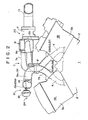
- Figure 1 is a schematic plan view showing a V-6 engine provided with an intake system in accordance with a first embodiment of the present invention,
- Figure 2 is a fragmentary front view of the engine,
- Figure 3 is a block diagram for illustrating the controller,
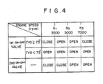
- Figure 4 shows the timing at which the first and second on-off valves are opened or closed,
- Figure 5 shows the engine output torque properties obtained by the intake system of the first embodiment,
- Figure 6 is a schematic plan view of an intake system in accordance with a second embodiment of the present invention,
- Figure 7 is a fragmentary front view of the intake system,
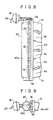
- Figure 8 is a fragmentary plan view for illustrating a modification of the first embodiment,
- Figure 9 is a front view of for illustrating the modification,
- Figure 10 is a front view of a V-6 engine provided with an intake system in accordance with a third embodiment of the present invention,
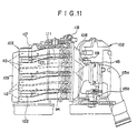
- Figure 11 is a plan view of the engine,
- Figure 12 is a side view of the engine, and
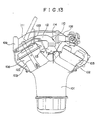
- Figure 13 is a cross-sectional view of the engine.
- In Figures 1 and 2, a V-6
engine 1 provided with an intake system in accordance with a first embodiment of the present invention comprises left andright cylinder banks cylinder block 2 and left andright cylinder heads cylinder block 2 at an angle to each other.Numbers left cylinder bank 1A andnumbers right cylinder bank 1B. Theintake ports 4 of the cylinders in each cylinder bank open in the inner surface of the cylinder bank opposed to theintake ports 4 of the cylinders in the other cylinder bank. - The intake system of this embodiment includes an
intake manifold 6 which formsdiscrete intake passages 6a to 6f respectively connected to theintake ports 4 for thenumbers 1 to 6 cylinders, and asurge tank 8 to which the upstream ends of thediscrete intake passages 6a to 6f are connected. - The
surge tank 8 is disposed above theright cylinder bank 1B, and has first andsecond chambers surge tank 8 is in the form of an elongated box extending in the direction of the crankshaft and the inside of thesurge tank 8 is divided into the first andsecond chambers partition wall 8c. Thefirst chamber 8a is in the rear of thesecond chamber 8b. Thediscrete intake passages left cylinder bank 1A which is remote from thesurge tank 8 are connected to thefirst chamber 8a, and thediscrete intake passages right cylinder bank 1B are connected to thesecond chamber 8b. That is, the intake strokes do not occur successively in the cylinders connected to each chamber. - A
throttle body 11 is connected to thesurge tank 8 on the side opposite to thediscrete intake passages 6a to 6f. Thethrottle body 11 has a pair of passages which are respectively communicated with the first andsecond chambers throttle valbes common intake passage 13 is connected to thethrottle body 11 and the first andsecond chambers surge tank 8 are communicated with each other in thecommon intake passage 13. The upstream end of thecommon intake passage 13 is connected to an airflow meter AFM and an air cleaner AC. - The
intake manifold 7 which forms thediscrete intake passages 6a to 6f is formed of upper andlower halves upper half 7a forms the upstream side portion of thediscrete intake passages 6a to 6f and is integral with thesurge tank 8, and thelower half 7b forms the downstream side portion of thediscrete intake passages 6a to 6f. The upper andlower halves cylinder banks - In the
lower half 7b, thediscrete intake passages left cylinder bank 1A obliquely extend upward toward the middle of the space between thecylinder banks upper half 7a, they extend upward and then are gently bent rearward and connected to thefirst chamber 8a of thesurge tank 8 which is disposed above theright cylinder bank 1B. In thelower half 7b, thediscrete intake passages right cylinder bank 1B obliquely extend upward toward the middle of the space between thecylinder banks upper half 7a, they extend upward and then are gently bent forward and connected to thesecond chamber 8b of thesurge tank 8 which is disposed above theright cylinder bank 1B. In the joint surface F, the discrete intake passages connected to theleft cylinder bank 1A and those connected to theright cylinder bank 1B are alternately arranged in the direction of the crankshaft. The lengths of thediscrete intake passages 6a to 6f are substantially equal to each other. - A first on-off
valve 15 is provided in an opening which is formed in thepartition wall 8c of thesurge tank 8 and communicates the first andsecond chambers valve 15 is opened and closed by afirst actuator 17 and the purpose of the first on-offvalve 15 will become apparent later. - A
branch passages 9a to 9f branch off from the respectivediscrete intake passages 6a to 6f in theupper half 7a of theintake manifold 7 and extend toward theleft cylinder bank 1A. First andsecond volume chambers left cylinder bank 1A with thefirst volume chamber 19a being forward of thesecond volume chamber 19b. Thebranch passages 9a to 9c which branch off from thediscrete intake passages 6a to 6c for thenumbers 1 to 3 cylinders are connected to thefirst volume chamber 19a and thebranch passages 9d to 9f which branch off from thediscrete intake passages 6d to 6f for thenumbers 1 to 3 cylinders are connected to thesecond volume cahmber 19b. The discrete intake passages connected to each of thevolume chambers branch passages 9a to 9f is provided with a second on-offvalve 16 at its junction to the volume chamber. The second on-offvalves 16 in the branch passages connected to each of the volume chambers are supported by a common shaft, and all the second on-offvalves 16 are actuated by asecond actuator 18. The purpose of the second on-offvalves 16 will be come apparent later. - In this particular embodiment, the
engine 1 is supercharged by both the interia supercharing effect and the resonance supercharging effect. The resonance selectively communicated with one of the enlarged volume chambers according to the engine speed, the inertia supercharging effect can be obtained in a wider engine speed range. However, this approach gives rise to a problem that the intake system is apt to be complicated and cumbersome. This problem is especially serious in the case of a V-type engine. - In view of the foregoing observations and description, the primary object of the present invention is to provide an intake system for a V-type engine which has a pair of pressure wave reflecting portions at different distances from the intake ports of the engine and nevertheless can be compactly arranged.
- In accordance with the present invention, there is provided an intake system for a V-type engine having a plurality of cylinders formed in a pair of cylinder banks comprising a first volume chamber which is communicated with the atmosphere through a common intake passage provided with a throttle valve, discrete intake passages which branch off from the surge tank and are connected to the respective cylinders, branch passages which branch off from the respective discrete intake passages, one or more second volume chambers each of which is communicated with at least two of the branch passages, on-off valves which are respectively provided in the branch passages and are opened and closed according to the operating condition of the engine, said first volume chamber being supercharging effect is obtained when the natural frequency of the intake system consisting of each of the
chambers surge tank 8 and the discrete intake passages connected thereto comes to resonate with the engine speed and to generate a stationary pressure wave and the statioary pressure wave acts on theintake ports 4 at the end of the intake stroke. When thefirst actuator 17 opens the first on-offvalve 15, the first andsecond chambers valve 15 is closed. That is, the first on-offvalve 15 and thefirst actuator 17 form aresonance changing mechanism 20 which changes the engine speed range in which the resonance supercharging effect can be obtained. In this embodiment, the intake stroke occurs in thenumbers 1 to 6 cylinders in this order (that is, the firing order is 1-2-3-4-5-6), and the intakes strokes in the cylinders connected to each of thechambers surge tank 8 do not occur successively. Accordingly, the intake air interference does not occur and the resonance supercharging effect can be surely obntained. - The vibrating force generated at each
intake port 4 propagate upstream the corresponding discrete intake passage, and vibrates the air in the part of the intake passage between theintake port 4 and thesurge tank 8 when the second on-offvalve 16 is closed, and vibrates the air in the part of the intake passage between theintake port 4 and thevolume chamber valve 16 is opened. When the vibration of the air in the part of the intake passage tunes to the closure of theintake port 4, the inertia supercharging effect can be obtained. When the second on-offvalve 16 is closed, the part of the intake passage which participates the vibration is longer than that when the second on-offvalve 16 is opened, and the inertia supercharging effect is obtained in a lower engine speed range. That is, the second on-offvalve 16 and thesecond actuator 18 form aninertia changing mechanism 21 which changes the engine speed range in which the inertia supercharging effect can be obtained. Further, when the second on-offvalves 16 are opened, intake air is introduced into each cylinder from the discrete intake passages for the other cylinders through the branch passages and thevolume chamber - The
resonance changing mechanism 20 and theinertia changing mechanism 21 are controlled by acontroller 22 shown in Figure 3. - The
first actuator 17 is driven by a negative pressure applied thereto through a negativepressure introduction passage 23 which is provided with a first three-way solenoid valve 25, and thesecond actuator 18 is driven by a negative pressure applied thereto through a negativepressure introduction passage 24 which is provided with a second three-way solenoid valve 26. Thecontroller 22 has a pair of drivingcircuits way solenoid valves second actuators - An engine speed signal from an
rpm sensor 30 of an enginespeed detecting means 29 and a throttle opening signal from athrottle sensor 31 which detects the openings of thethrottle valves controller 22. The engine speed signal is input into first tothird comparators 32 to 34 and the throttle opening signal is input into afourth comparator 35. Thefirst comparator 32 compares the engine speed signal with a first reference value N1 which corresponds to 3500rpm, thesecond comparator 33 compares the engine speed signal with a second reference value N2 corresponding to 5000rpm, thethird comparator 34 compares the engine speed signal with a third reference value corresponding to 7000rpm, and thefourth comparator 35 compares the throttle opening signal with a fourth reference value To corresponding to 73°. The outputs of the first andthird comparators circuit 37 by way of agate circuit 36. The output of thefourth comparator 35 is also input into theOR circuit 37. The output of theOR circuit 37 is input into the drivingcircuit 27 which drives thefirst solenoid valves 25 of theresonance changing mechanism 20. The output of thesecond comparator 33 is input into the drivingcircuit 28 which drives thesecond solenoid valve 26 of theinertia changing mechanism 21. - The
controller 22 causes theresonance changing mechanism 20 and theinertia changing mechanism 21 to open and close the first and second on-offvalves valve 15 is closed in a heavy load, low engine speed range where the throttle opening is not smaller than 73° and the engine speed is not higher than 3500rpm, and in a heavy load, high engine speed range where the throttle opening is not smaller than 73° and the engine speed is not lower than 7000rpm. In the other ranges, the first on-offvalve 15 is opened. The second on-offvalve 16 is closed irrespective of the throttle opening when the engine speed is not higher than 5000rpm, and is opened when the enghine speed is higher than 5000rpm. - When the first and second on-off
valves valves valve 15 is kept closed and the second on-offvalve 16 is kept open over the entire engine speed range. Curve III shows the relation between the engine speed and the engine output torque when the first on-offvalve 15 is kept open and the second on-offvalve 16 is kept closed over the entire engine speed range. Curve IV shows the relation between the engine speed and the engine output torque when both the first and second on-offvalves valves valve 15 is opened and the second on-offvalve 16 is closed, and in the high engine speed range between 5000rpm and 7000rpm, a maximum engine output torque can be obatined when the first and second on-offvalves valve 15 is closed and the second on-offvalve 16 is opened. Accordingly, when the first and second on-offvalves - Since the engine output torque need not be so high in the light load range where the throttle opening is smaller than 73°, the first on-off
valve 15 is kept closed over the entire engine speed range so that the engine output torque shown by Curve III is obtained when the engine speed is lower than 5000rpm. That is, when the throotle opening is smaller than 73°, neither the first on-offvalve 15 nor the second on-offvalve 16 is switched in the engine speed range below 5000rpm, whereby the torque shock produced in response to switching of the valves can be avoided. In the case of a vehicle whose usual operating engine speed range is lower than 7000rpm, the first on-offvalve 15 need not be switched at 7000rpm. - In accordance with this embodiment, the volumetric efficiency of the engine can be improved and the engine output torque can be increased over a wide engine speed range by the inertia supercharging effect or the resonance supercharging effect without use of any supercharger.
Figures 6 and 7 show an intake system in accordance with a second embodiment of the present invention. In Figures 6 and 7, the parts analogous to the parts shown in Figures 1 and 2 are given the same reference numerals and will not be described here. - Similarly to the first embodiment, the
discrete intake passages left cylinder bank 1A are connected to thefirst chamber 8a of thesurge tank 8, and thediscrete intake passages right cylinder bank 1B are connected to thesecond chamber 8b. Thechambers opening 8c which is closed and opened by the first on-offvalve 15 of aresonance changing mechanism 40. - The
discrete intake passages 6a to 6f are arranged in a row in the space between the left andright cylinder banks branch passages discrete intake passages 6a to 6f. The branch passages which branch off from the discrete intake passages for the cylinders in theleft cylinder bank 1A are connected to afirst volume chamber 42a, and the branch passages which branch off from the discrete intake passages for the cylinders in theright cylinder bank 1B are connected to asecond volume chamber 42b which is disposed below thefirst volume chamber 42a. Thebranch passages 9a to 9f are respectively provided with the second on-offvalves 16. The second on-offvalves 16 for thebranch passages first volume chamber 42a are supported on afirst shaft 43 and are integrally closed and opened. The second on-offvalves 16 for thebranch passages second volume chamber 42b are supported on asecond shaft 44 and are integrally closed and opened. A second actuator (not shown) which forms together with the second on-offvalves 16 aninertia changing mechanism 41 is connected to each of theshafts valves 16. - The first and second on-off
valves - In this embodiment, the intake stroke does not occur successively in the cylinders communicated with each of the first and
second volume chambers second volume chambers valves 16 are opened in the high engine speed range (5000 to 7000rpm), air flows into the cylinders in the intake stroke from the discrete intake passages for the other cylinders, whereby the volumetric efficiency can be improved bettter than in the first embodiment. - Figures 8 and 9 show a modification of the first embodiment.
- In this modification, the
branch passages 9a to 9f which branch off from thediscrete intake passages 6a to 6f are connected to asingle volume chamber 45 which is formed separately from theupper half 7a of theintake manifold 7. Thevolume chamber 45 has an integralinner space 45a and all thebranch passages 9a to 9f are communicated with theinner space 45a, whereby thediscrete intake passages 6a to 6f are communicated with one another by way of theinner space 45a of thevolume chamber 45. Each of thebranch passages 9a to 9f is provided with the second on-offvalve 16 at the junction to thevolume chamber 45. The second on-offvalves 16 for therespective branch passages 9a to 9f are fixed to asingle shaft 46 and integrally driven by thesecond actuator 18. - In order to further improve the volumetric efficiency when the second on-off
valves 16 are opened as described above, it is preferred that the cylinders be connected to the volume chambers so that the intake stroke does not occur successively in the cylinders connected to each volume chamber as in the first embodiment. However, cylinders in which the intake stroke occurs successively may be connected to a volume chamber as in the second embodiment or the modification of the first embodiment. Further, in the case where the branch passages are comnnected to separate volume chambers, the volume chambers need not be communicated with each other so long as each volume chamber can reflect the pressure wave which propagates through the branch passages. - Further, though, in the first embodiment, also the engine speed range in which the resonance supercharging effect can be obtained is changed by opening and closure of the first on-off
valve 15 provided between the first andsecond chambers surge tank 8, thereby supercharging the engine by the kinetic effect of intake air in a wider engine speed range, it is not necessarily needed. But thesurge tank 8 may be arranged so that the resonance supercharging effect can be obtained just in a particular engine speed range. - Figures 10 to 13 show a third embodiment of the present invention.
- In Figures 10 to 13, a V-
type engine 101 has right and leftcylinder heads cylinder banks cylinders 104 are formed in each cylinder head.Intake ports 107 are formed in the inner faces of the right and leftcylinder heads first surge tank 108 extends in the longitudinal direction of theengine 101 above theright cylinder bank 102. Asecond surge tank 109 extends in the longitudinal direction of theengine 101 above theleft cylinder bank 103. - The
first surge tank 108 is connected to athrottle body 115 which will be described later. Thefirst surge tank 108 is connected to each of theintake ports 107 by way of a high-engine-speed intake passage 110 whose effective length is short. Thefirst surge tank 108 is communicated with thesecond surge tank 109 by way of a communicating passage 111 which extends across the space between thecylinder banks - The
second surge tank 109 is commuincated with eachintake port 107 by way of a low-engine-speed intake passage 112 which is relatively long is the effective length and is disposed below the communicating passage 111. - Each high-engine-
speed intake passage 110 and each low-engine-speed intake passage 112 are merged together at the middle between the right and leftcylinder banks intake ports 107 in the right and leftcylinder banks bifurcated pipe 113 . Each high-engine-speed intake passage 110 is provided with an on-offvalve 114 at the junction thereof to the low-engine-speed intake passage 112. The shape and the position of the on-offvalve 114 is selected so that it does not change the cross-sectional area of the low-engine-speed intake passage 112 and does not increase intake resistance in the low-engine-speed intake passage 112, thereby preventing torque shock from occurring in the low engine speed range where intake air is introduced into the cylinders through the low-engine-speed intake passage 112. For this purpose, the surface facing theintake port 107 may be of a concave surface having a large radius of curvature, for instance. - The distance from the middle between the
cylinder banks first surge tank 108 is shorter than that of thesecond surge tank 109. With this arrangement, the effective length of the high-engine-speed intake passage 110 can be made shorter, and a space remains above theright cylinder bank 103.Said throttle body 115 is disposed in the space above theright cylinder bank 103.Reference numeral 115a denotes a pipe which communicates thethrottle body 115 to an air cleaner and is demountably mounted on thethrottle body 115, and reference numeral 115b denotes an idle speed controller. - In the intake system of this embodiment, the on-off valves 14 are closed and the high-engine-
speed intake passages 110 are closed in the low engine speed range, and intake air first flows into thefirst surge tank 108 through thethrottle body 115 and then into eachcylinder 4 through the communicating passage 111, thesecond surge tank 109 and the low-engine-speed intake passage 112. - That is, in the low engine speed range, the first and
second surge tanks - In the high engine speed range, the on-off valves 14 are opened and the high-engine-
speed intake passages 110 are opened. Accordingly, the major part of intake air is introduced into eachcylinder 4 through the high-engine-speed intake passage 110 which is short in the effective length, though a part of the intake air is introduced into eachcylinder 4 through the low-engine-speed intake passages 112. - Since the
first surge tank 108 is toward the middle between thecylinder banks throttle body 115 is disposed in the space above theright cylinder bank 103, the part of the intake system upstream of thefirst surge tank 108 inlcuding thethrottle body 115 and the air cleaner can be made short, whereby positioning of the part of the intake system is facilitated and the part can be copactly arranged. Further the appearance of the inside of the engine room is improved, and the engine becomes easy to assemble and to maintain. - Further, since part of the intake system upstream of the
first surge tank 108 can be shortened and the high-engine-speed intake passages 110 can be shortened, the intake resistance can be substantially reduced in the high engine speed range and accordingly the volumetric efficiency in the high engine speed range can be substantially improved. - The cross-sectional area of the
first surge tank 108 gradually increases from the intake air inlet on the side of thethrottle body 115 toward the downstream side along the flow line of intake air, whereby intake air can be more evenly distributed to the cylinders in the high engine speed range. - The communicating passage 111 which is positioned highest in the intake system is disposed toward the rear side of the first and
second surge tanks - An
EGR passage 116 and a blow-bygas passage 117 is connected to the communicating passage 111. TheEGR passage 116 is led from anEGR valve 118 and is connected to an upstream side portion of the communicating passage 111. The blow-bygas passage 117 is led from theleft cylinder head 106 and is connected a downstream side portion of the communicating passage 111. With this arrangement, the EGR gas and the blow-by gas flow through a long passage including the communicating passage 111, thesecond surge tank 109 and the low-engine-speed intake passage 112, and accordingly the gasses are sufficiently mixed with air and uniformly distributed to thecylinders 4. - Further, when the
EGR gas passage 117 is connected to the communicating passage 111 upstream of the blow-bygas passage 116, the EGR gas which can adversely affect emission can be sufficiently mixed with air and at the same time, the oil component in the blow-by gas cannot stick to the opening of theEGR gas passage 117. A cold-start injector 119 is provided in the passage between the throotle valve in the throttle body and thefirst surge tank 108. When the cold-start injector 119 is in such a position, the fuel injected from the injector during cold-start flows togther with intake air over a long passage including thefirst surge tank 108, the communicating passage 111, thesecond surge tank 109 and the low-engine-speed intake passage 112 before it enters the cylinder, and accordingly it can be sufficiently mixed with air and uniformly distributed to thecylinders 4. - A
vacuum chamber 121 which functions as a negative pressure reservoir for a brake masterback or the like is connected to thebifurcated pipe 113 by way of acheck valve 120 which is opened and closed according to the intake vacuum. Thevacuum chamber 121 is disposed in a space defined by the upper portion of the cylinder heads and thebifurcated pipes 113. With this arrangement, thevacuum chamber 121 can be disposed while making the best use of the upper portion of the space between thecylinder banks vacuum chamber 121 can be positioned close to thecylinders 4 which are negative pressure sources, thevacuum chamber 121 can store a large negative pressure. Further, the arrangement can contribute toward in compactly arranging thevaccum chamber 121 and the brake masterback. - The intake manifold which forms the low-engine-
speed intake passage 112 does not occupy the space above the spark plug mounting position for eachcylinder 4 in theleft cylinder bank 103, and aplug cap 122 is inserted into the space. A high-tension code 123 which is integrally connected to eachplug cap 122 is fixed to the cylinder head cover on theleft cylinder head 106.
Claims (13)
Applications Claiming Priority (4)
| Application Number | Priority Date | Filing Date | Title |
|---|---|---|---|
| JP263319/88 | 1988-10-19 | ||
| JP63263319A JP2721983B2 (en) | 1988-10-19 | 1988-10-19 | V-type engine intake system |
| JP15571289A JP2532666B2 (en) | 1989-06-20 | 1989-06-20 | V-type engine intake device |
| JP155712/89 | 1989-06-20 |
Publications (3)
| Publication Number | Publication Date |
|---|---|
| EP0365016A2 true EP0365016A2 (en) | 1990-04-25 |
| EP0365016A3 EP0365016A3 (en) | 1991-05-02 |
| EP0365016B1 EP0365016B1 (en) | 1994-06-15 |
Family
ID=26483641
Family Applications (1)
| Application Number | Title | Priority Date | Filing Date |
|---|---|---|---|
| EP89119439A Expired - Lifetime EP0365016B1 (en) | 1988-10-19 | 1989-10-19 | Intake system for V-type engine |
Country Status (3)
| Country | Link |
|---|---|
| US (1) | US4977865A (en) |
| EP (1) | EP0365016B1 (en) |
| DE (1) | DE68916158T2 (en) |
Cited By (7)
| Publication number | Priority date | Publication date | Assignee | Title |
|---|---|---|---|---|
| DE4110597A1 (en) * | 1990-03-30 | 1991-10-02 | Mazda Motor | INLET SYSTEM FOR A MULTI-CYLINDER INTERNAL COMBUSTION ENGINE |
| DE4117466A1 (en) * | 1990-05-28 | 1991-12-05 | Mazda Motor | INTAKE SYSTEM FOR A MULTI-CYLINDER INTERNAL COMBUSTION ENGINE |
| EP0483672A1 (en) * | 1990-10-29 | 1992-05-06 | Mazda Motor Corporation | An engine induction system |
| DE4041786A1 (en) * | 1990-12-24 | 1992-06-25 | Opel Adam Ag | Electronically-controlled variable air intake for IC engine - has channel interconnecting outlets from resonance tubes, blocked or unblocked according to temp. and engine speed |
| WO1992014914A1 (en) * | 1991-02-21 | 1992-09-03 | Vickers Plc | Exhaust gas control system |
| EP0664390A1 (en) * | 1994-01-25 | 1995-07-26 | FILTERWERK MANN & HUMMEL GMBH | Integral suction system |
| FR2904376A1 (en) * | 2006-07-25 | 2008-02-01 | Mann & Hummel Gmbh | Air intake manifold for internal combustion engine i.e. oil engine, of motor vehicle, has chamber situated below ramp that supplies injectors, where chamber includes compartments connected by pipes to define spaces for passing cams |
Families Citing this family (10)
| Publication number | Priority date | Publication date | Assignee | Title |
|---|---|---|---|---|
| JP2858706B2 (en) * | 1990-03-31 | 1999-02-17 | マツダ株式会社 | V-type engine intake system |
| JPH03286125A (en) * | 1990-03-31 | 1991-12-17 | Mazda Motor Corp | Intake device of engine |
| DE4017049A1 (en) * | 1990-05-26 | 1991-11-28 | Opel Adam Ag | PIPE SYSTEM FOR AN INTERNAL COMBUSTION ENGINE |
| JP2001280206A (en) * | 2000-03-31 | 2001-10-10 | Aisin Seiki Co Ltd | Intake device of engine |
| DE10026358B4 (en) * | 2000-05-27 | 2005-06-30 | Mahle Filtersysteme Gmbh | Internal combustion engine with intake system |
| JP2005002941A (en) * | 2003-06-13 | 2005-01-06 | Mikuni Corp | Intake manifold |
| US7004137B2 (en) * | 2003-12-10 | 2006-02-28 | Nissan Motors Co., Ltd | V-type multiple-cylinder air intake device |
| US20050161013A1 (en) * | 2004-01-23 | 2005-07-28 | Marriott Craig D. | Efficient internal combustion engine operation using intake manifold tuning |
| US7597088B2 (en) * | 2005-08-26 | 2009-10-06 | Mj Acquisitions, Inc. | Apparatus and method for boosting engine performance |
| US8181728B2 (en) * | 2008-04-17 | 2012-05-22 | Mj Acquisitions, Inc. | Automotive vehicle engine apparatus |
Citations (1)
| Publication number | Priority date | Publication date | Assignee | Title |
|---|---|---|---|---|
| FR2591665A1 (en) * | 1985-10-11 | 1987-06-19 | Fiat Auto Spa | Inlet manifold for combustion engines, in particular for internal combustion engines for motor vehicles |
Family Cites Families (6)
| Publication number | Priority date | Publication date | Assignee | Title |
|---|---|---|---|---|
| JPS60164619A (en) * | 1984-02-06 | 1985-08-27 | Toyota Motor Corp | Suction device for multicylinder internal-combustion engine |
| US4727829A (en) * | 1985-04-23 | 1988-03-01 | Yamaha Hatsudoki Kabushiki Kaisha | Intake system for internal combustion engine |
| US4765285A (en) * | 1985-08-07 | 1988-08-23 | Yamaha Hatsudoki Kabushiki Kaisha | Intake system for internal combustion engine |
| JPH07101008B2 (en) * | 1986-01-14 | 1995-11-01 | ヤマハ発動機株式会社 | Multi-cylinder engine intake system |
| DE3702827A1 (en) * | 1987-01-30 | 1988-08-11 | Bayerische Motoren Werke Ag | INTAKE SYSTEM WITH A CONTROL DEVICE, ESPECIALLY FOR COMBUSTION ENGINES |
| GB2202276B (en) * | 1987-03-09 | 1991-09-18 | Honda Motor Co Ltd | Intake device for internal combustion engine |
-
1989
- 1989-10-18 US US07/423,205 patent/US4977865A/en not_active Expired - Fee Related
- 1989-10-19 EP EP89119439A patent/EP0365016B1/en not_active Expired - Lifetime
- 1989-10-19 DE DE68916158T patent/DE68916158T2/en not_active Expired - Fee Related
Patent Citations (1)
| Publication number | Priority date | Publication date | Assignee | Title |
|---|---|---|---|---|
| FR2591665A1 (en) * | 1985-10-11 | 1987-06-19 | Fiat Auto Spa | Inlet manifold for combustion engines, in particular for internal combustion engines for motor vehicles |
Non-Patent Citations (4)
| Title |
|---|
| PATENT ABSTRACTS OF JAPAN vol. 11, no. 218 (M-607)(2665), 15 July 1987; & JP - A - 6235021 (YAMAHA MOTOR CO. LTD.) 16.02.1987 * |
| PATENT ABSTRACTS OF JAPAN vol. 11, no. 301 (M-628), 30 September 1987; & JP - A - 6291621 (MAZDA) 27.04.1987 * |
| PATENT ABSTRACTS OF JAPAN vol. 11, no. 50 (M-562)(2497), 17 February 1987; & JP - A - 61212627 (YAMAHA MOTOR CO. LTD.) 20.09.1986 * |
| PATENT ABSTRACTS OF JAPAN vol. 11, no. 82 (M-571)(2529), 12 March 1987; & JP - A - 61237823 (MAZDA) 23.10.1986 * |
Cited By (12)
| Publication number | Priority date | Publication date | Assignee | Title |
|---|---|---|---|---|
| DE4110597A1 (en) * | 1990-03-30 | 1991-10-02 | Mazda Motor | INLET SYSTEM FOR A MULTI-CYLINDER INTERNAL COMBUSTION ENGINE |
| DE4110597C2 (en) * | 1990-03-30 | 2003-12-04 | Mazda Motor | Intake air intake system for a multi-cylinder internal combustion engine |
| DE4117466A1 (en) * | 1990-05-28 | 1991-12-05 | Mazda Motor | INTAKE SYSTEM FOR A MULTI-CYLINDER INTERNAL COMBUSTION ENGINE |
| EP0483672A1 (en) * | 1990-10-29 | 1992-05-06 | Mazda Motor Corporation | An engine induction system |
| US5168838A (en) * | 1990-10-29 | 1992-12-08 | Mazda Motor Corporation | Engine induction system |
| DE4041786A1 (en) * | 1990-12-24 | 1992-06-25 | Opel Adam Ag | Electronically-controlled variable air intake for IC engine - has channel interconnecting outlets from resonance tubes, blocked or unblocked according to temp. and engine speed |
| DE4041786C2 (en) * | 1990-12-24 | 2003-04-30 | Opel Adam Ag | Intake system intended for an internal combustion engine |
| WO1992014914A1 (en) * | 1991-02-21 | 1992-09-03 | Vickers Plc | Exhaust gas control system |
| EP0664390A1 (en) * | 1994-01-25 | 1995-07-26 | FILTERWERK MANN & HUMMEL GMBH | Integral suction system |
| US5477819A (en) * | 1994-01-25 | 1995-12-26 | Filterwerk Mann & Hummel Gmbh | Integrated air intake system |
| TR28363A (en) * | 1994-01-25 | 1996-05-30 | Mann & Hummel Filter | Integrated suction system. |
| FR2904376A1 (en) * | 2006-07-25 | 2008-02-01 | Mann & Hummel Gmbh | Air intake manifold for internal combustion engine i.e. oil engine, of motor vehicle, has chamber situated below ramp that supplies injectors, where chamber includes compartments connected by pipes to define spaces for passing cams |
Also Published As
| Publication number | Publication date |
|---|---|
| US4977865A (en) | 1990-12-18 |
| DE68916158T2 (en) | 1994-09-22 |
| EP0365016A3 (en) | 1991-05-02 |
| DE68916158D1 (en) | 1994-07-21 |
| EP0365016B1 (en) | 1994-06-15 |
Similar Documents
| Publication | Publication Date | Title |
|---|---|---|
| US4977865A (en) | Intake system for V-type engine | |
| US4679531A (en) | Intake system for internal combustion engine | |
| US4671217A (en) | Intake system for internal combustion engine | |
| EP0265960A2 (en) | Intake system for multiple-cylinder engine | |
| US4957071A (en) | Intake system for V-type internal combustion engine | |
| US4846117A (en) | Intake system for multiple-cylinder engine | |
| US4765285A (en) | Intake system for internal combustion engine | |
| US5937815A (en) | Air intake system for internal combustion engine | |
| US4771740A (en) | Intake system for internal combustion engine | |
| JP3353191B2 (en) | Multi-cylinder V-type engine | |
| US4889082A (en) | Intake system for multiple-cylinder engine | |
| US4735177A (en) | Intake system for internal combustion engine | |
| US5490484A (en) | Air intake system of an internal-combustion engine | |
| US4858570A (en) | V-type engine | |
| US4989553A (en) | Air intake device of engine | |
| EP0450546A1 (en) | Intake system for a combustion engine | |
| JP3747586B2 (en) | Intake control device for internal combustion engine | |
| JPH0240021A (en) | Intake structure of v-engine | |
| JP2716172B2 (en) | Intake system for 4-cycle V-type multi-cylinder engine | |
| JPH078814Y2 (en) | Engine intake and exhaust pipe structure | |
| JPH0392534A (en) | Intake device for multi-cylinder engine | |
| JPH02271025A (en) | Exhaust structure of multicylinder engine | |
| JPH0726541B2 (en) | Engine intake system | |
| JPH0598969A (en) | Intake device for v-shaped multicylinder engine | |
| JPH03100320A (en) | Intake device of multi-cylinder engine |
Legal Events
| Date | Code | Title | Description |
|---|---|---|---|
| PUAI | Public reference made under article 153(3) epc to a published international application that has entered the european phase |
Free format text: ORIGINAL CODE: 0009012 |
|
| AK | Designated contracting states |
Kind code of ref document: A2 Designated state(s): DE FR GB |
|
| PUAL | Search report despatched |
Free format text: ORIGINAL CODE: 0009013 |
|
| RHK1 | Main classification (correction) |
Ipc: F02B 27/02 |
|
| AK | Designated contracting states |
Kind code of ref document: A3 Designated state(s): DE FR GB |
|
| 17P | Request for examination filed |
Effective date: 19910620 |
|
| 17Q | First examination report despatched |
Effective date: 19920630 |
|
| GRAA | (expected) grant |
Free format text: ORIGINAL CODE: 0009210 |
|
| AK | Designated contracting states |
Kind code of ref document: B1 Designated state(s): DE FR GB |
|
| REF | Corresponds to: |
Ref document number: 68916158 Country of ref document: DE Date of ref document: 19940721 |
|
| ET | Fr: translation filed | ||
| PLBE | No opposition filed within time limit |
Free format text: ORIGINAL CODE: 0009261 |
|
| STAA | Information on the status of an ep patent application or granted ep patent |
Free format text: STATUS: NO OPPOSITION FILED WITHIN TIME LIMIT |
|
| 26N | No opposition filed | ||
| PGFP | Annual fee paid to national office [announced via postgrant information from national office to epo] |
Ref country code: FR Payment date: 20011010 Year of fee payment: 13 |
|
| PGFP | Annual fee paid to national office [announced via postgrant information from national office to epo] |
Ref country code: GB Payment date: 20011017 Year of fee payment: 13 |
|
| REG | Reference to a national code |
Ref country code: GB Ref legal event code: IF02 |
|
| PG25 | Lapsed in a contracting state [announced via postgrant information from national office to epo] |
Ref country code: GB Free format text: LAPSE BECAUSE OF NON-PAYMENT OF DUE FEES Effective date: 20021019 |
|
| GBPC | Gb: european patent ceased through non-payment of renewal fee |
Effective date: 20021019 |
|
| PG25 | Lapsed in a contracting state [announced via postgrant information from national office to epo] |
Ref country code: FR Free format text: LAPSE BECAUSE OF NON-PAYMENT OF DUE FEES Effective date: 20030630 |
|
| REG | Reference to a national code |
Ref country code: FR Ref legal event code: ST |
|
| PGFP | Annual fee paid to national office [announced via postgrant information from national office to epo] |
Ref country code: DE Payment date: 20051014 Year of fee payment: 17 |
|
| PG25 | Lapsed in a contracting state [announced via postgrant information from national office to epo] |
Ref country code: DE Free format text: LAPSE BECAUSE OF NON-PAYMENT OF DUE FEES Effective date: 20070501 |