EP0364984A2 - Interferometer using multi-mode semiconductor laser - Google Patents
Interferometer using multi-mode semiconductor laser Download PDFInfo
- Publication number
- EP0364984A2 EP0364984A2 EP89119346A EP89119346A EP0364984A2 EP 0364984 A2 EP0364984 A2 EP 0364984A2 EP 89119346 A EP89119346 A EP 89119346A EP 89119346 A EP89119346 A EP 89119346A EP 0364984 A2 EP0364984 A2 EP 0364984A2
- Authority
- EP
- European Patent Office
- Prior art keywords
- laser
- interference
- diffraction grating
- laser beam
- beams
- Prior art date
- Legal status (The legal status is an assumption and is not a legal conclusion. Google has not performed a legal analysis and makes no representation as to the accuracy of the status listed.)
- Granted
Links
- 239000004065 semiconductor Substances 0.000 title claims abstract description 38
- 230000003287 optical effect Effects 0.000 claims abstract description 36
- 238000001228 spectrum Methods 0.000 claims abstract description 36
- 230000010355 oscillation Effects 0.000 claims abstract description 33
- 238000006073 displacement reaction Methods 0.000 claims abstract description 14
- 230000005855 radiation Effects 0.000 claims description 10
- 238000000034 method Methods 0.000 claims description 7
- 238000006243 chemical reaction Methods 0.000 claims description 5
- 238000001514 detection method Methods 0.000 claims description 5
- 230000005611 electricity Effects 0.000 claims description 2
- 230000000694 effects Effects 0.000 abstract description 3
- 230000003595 spectral effect Effects 0.000 description 11
- 238000005259 measurement Methods 0.000 description 5
- 230000007613 environmental effect Effects 0.000 description 4
- 230000008859 change Effects 0.000 description 3
- 230000009467 reduction Effects 0.000 description 3
- 230000007423 decrease Effects 0.000 description 2
- 230000000737 periodic effect Effects 0.000 description 2
- 238000004088 simulation Methods 0.000 description 2
- 230000009466 transformation Effects 0.000 description 2
- 238000004364 calculation method Methods 0.000 description 1
- 238000010586 diagram Methods 0.000 description 1
- 230000002452 interceptive effect Effects 0.000 description 1
- 230000007246 mechanism Effects 0.000 description 1
- 230000002265 prevention Effects 0.000 description 1
Images


Classifications
-
- G—PHYSICS
- G01—MEASURING; TESTING
- G01D—MEASURING NOT SPECIALLY ADAPTED FOR A SPECIFIC VARIABLE; ARRANGEMENTS FOR MEASURING TWO OR MORE VARIABLES NOT COVERED IN A SINGLE OTHER SUBCLASS; TARIFF METERING APPARATUS; MEASURING OR TESTING NOT OTHERWISE PROVIDED FOR
- G01D5/00—Mechanical means for transferring the output of a sensing member; Means for converting the output of a sensing member to another variable where the form or nature of the sensing member does not constrain the means for converting; Transducers not specially adapted for a specific variable
- G01D5/26—Mechanical means for transferring the output of a sensing member; Means for converting the output of a sensing member to another variable where the form or nature of the sensing member does not constrain the means for converting; Transducers not specially adapted for a specific variable characterised by optical transfer means, i.e. using infrared, visible, or ultraviolet light
- G01D5/32—Mechanical means for transferring the output of a sensing member; Means for converting the output of a sensing member to another variable where the form or nature of the sensing member does not constrain the means for converting; Transducers not specially adapted for a specific variable characterised by optical transfer means, i.e. using infrared, visible, or ultraviolet light with attenuation or whole or partial obturation of beams of light
- G01D5/34—Mechanical means for transferring the output of a sensing member; Means for converting the output of a sensing member to another variable where the form or nature of the sensing member does not constrain the means for converting; Transducers not specially adapted for a specific variable characterised by optical transfer means, i.e. using infrared, visible, or ultraviolet light with attenuation or whole or partial obturation of beams of light the beams of light being detected by photocells
- G01D5/36—Forming the light into pulses
- G01D5/38—Forming the light into pulses by diffraction gratings
Definitions
- This invention relates to an interferometer having a multi-mode semiconductor laser used as a light source and, more particularly, to an interferometer which irradiates a moving diffraction grating with laser light, forms interference light from diffracted light emerging from the diffraction grating and measures the interference light.
- a type of encoder which detects the displacement of a scale by superposing diffracted lights emerging from a diffraction grating formed on the scale to form interference light and converting the same into an electrical signal.
- the periodic signal obtained by this type of encoder has improved resolution compared with encoders using the ordinary combination of a main scale and an index scale.
- the conditions for the occurrence of the interference of light must be established. In general, if the difference between the optical paths of two light beams to be made to interfere with each other (the difference between the times taken to reach the interfering position from the light source) is zero, the intensity of the interference signal is maximized irrespective of the type of light source.
- spectral width As the width of the spectrum of the light source (spectral width) becomes wider, the intensity of interference light decreases abruptly due to the slight difference between the optical paths of the two light beams.
- Lasers which emit light of very small spectral widths have, therefore, been used as light sources for interferometers, including the above-mentioned type of encoder, utilizing interference light.
- semiconductor lasers have many advantages, for example, that of being reduced in size and requiring a reduced driving current, and they therefore contribute to reductions in the overall size and the production cost of interferometers if they are incorporated therein as light sources.
- Semiconductor lasers include a single mode laser having one oscillation spectrum mode and a multi-mode laser having a plurality of oscillation spectrum modes.
- a single mode laser has improved interference performance (has a larger coherence length) but changes discontinuously with changes in operating temperature and driving current so that the phase of the interference signal changes discontinuously, resulting in errors in detecting changes in the intensity of interference light by counting periodic signals corresponding to these changes. For prevention of this phenomenon, it is necessary to add a system for accurately controlling the operating temperature and the driving current. The provision of such means necessarily makes the interferometer larger, more complicated and more expensive.
- multi-mode lasers ordinarily have shorter coherence lengths and various oscillation spectra. Their interference performance is therefore unstable. For this reason, they cannot be easily utilized in interferometers.
- an object of the present invention is to provide an interferometer capable of measuring interference with improved stability by using a multi-mode laser.
- the present invention provides in one of its aspects an interferometer employing, as a light source, a multi-mode laser having at least five vertical modes with an intensity ratio of 0.05 or higher.
- the intensity ratio is defined as the ratio of the intensity of the oscillation spectrum (wavelength spectrum) of the laser to the peak value of the oscillation spectrum of the laser when the peak value of the oscillation spectrum of the semiconductor laser is 1.
- the width of the oscillation spectrum (all modes or a predetermined mode) at an intensity ratio of 0.5 is called the half width.
- the present invention provides in another of its aspects an interferometer in which the laser beam emitted from a multi-mode laser is directed to a diffraction grating.
- An interference beam is formed from the diffracted beam generated at the diffraction grating, and is converted into an electrical signal, thereby measuring the displacement of the diffraction grating.
- the number of vertical modes of the laser at an intensity ratio of 0.05 or higher is set to five or more.
- the semiconductor laser is adjusted so as to satisfy the following two conditions in addition to the above conditions:
- a multi-mode semiconductor laser is used, as the laser, in a suitable manner to ensure that the amplitude of the interference signal (contrast) is stable during assembly or measurement, and that even if the optical path difference is changed by thermal expansions of the frame of the interferometer due to changes in the environmental temperature, the reduction in the amplitude of the interference signal is small and the occurrence of a discontinuity in the signal phase can be avoided.
- the present invention relates to an interferometer comprising a multi-mode semiconductor laser generating a laser beam having at least five vertical modes having an intensity ratio of at least 0.05, generation means for generating an interference light beam from a laser beam supplied from the laser, and detection means for detecting the interference light beam.
- the laser is constructed to generate a laser beam having an envelop that envelopes peaks of the respective vertical modes of the oscillation spectrum of the laser beam, such that the envelops has a width of no greater than 6 nm.
- the laser is also constructed so as to generate a laser beam such that the width of each of the at least five vertical modes is at least 0.03 nm, and has a coherency length of at least 100 ⁇ m.
- the generation means can include an optical system for splitting the laser beam into first and second beams and superposing the first and second beams.
- the detection means can include a photodetector capable of converting the interference light into electricity to generate a predetermined signal.
- the interferometer can also include means for supplying a driving current to the laser, the driving current determining the number of vertical modes.
- the present invention relates to method of measuring interference light comprising the steps of supplying laser radiation with a predetermined spectrum having at least five vertical modes with an intensity ratio of at least 0.05, forming an interference beam with the laser radiation, and detecting the interference beam.
- the present invention relates to an apparatus for measuring the displacement of a diffraction grating.
- the apparatus comprises a multi-mode semiconductor laser generating a laser beam having at least five vertical modes with an intensity ratio of at least 0.05; interference means for directing the laser beam from the laser to the diffraction grating and causing first and second diffracted light beams generated at the diffraction grating to interfere with each other to generate an interference light beam; and conversion means for converting the interference light beam supplied by the interference means into an electrical signal.
- the interference means is arranged to cause the optical path lengths of the first and second diffracted light beams to be substantially equal to each other.
- the laser is also constructed to generate a laser beam having an envelop, half width, and coherence length that satisfy the values noted above.
- the present invention relates to an apparatus for measuring the displacement of a diffraction grating that comprises a multi-mode semiconductor laser for generating laser beam; supply means for supplying a predetermined current to the laser so that at least five vertical modes occur in an oscillation spectrum of the laser beam generated by the laser at an intensity ratio of at least 0.05; interference means for splitting the laser beam generated by the laser into first and second beams, for directing the first and second beams to the diffraction grating, and for effecting interference between a first diffracted light beam generated by diffraction of the first beam at the diffraction grating and a second diffracted light beam generated by diffraction of the second beam at the diffraction grating to produce an interference light beam; and conversion means for converting the interference light beam supplied by the interference means into an electrical signal.
- the laser is also constructed to generate a laser beam having an envelop, half width, and coherence length with the values noted above.
- the interference means is arranged to cause the optical path length of the first and second diffracted light beams to be substantially equal to each other.
- the present invention relates to a method for measuring the displacement of a diffraction grating and comprises the steps of directing laser radiation with a predetermined spectrum having at least five vertical modes each having an intensity ratio of at least 0.05 to the diffraction grating; forming an interference beam from the diffraction beams generated at the diffraction grating; and converting the interference beam into an electrical signal.
- the forming step includes a step of superposing ⁇ 1-order diffraction beams generated by the diffraction grating to form the interference beam, the optical path lengths of the ⁇ 1-order beam being substantially equal.
- the directing step specifically comprises the step of directing to the diffraction grating laser radiation having an envelop which envelopes peaks of respective vertical modes of the oscillation spectrum, with the width of the envelop being no more than 6 nm and with the half width of each of the at least five vertical modes being at least 0.03 nm.
- the directing step can include the steps of providing a multi-mode semiconductor laser and supplying a predetermined current to the laser so to emit the laser radiation from the laser.
- Figs. 1A and 1B illustrate features of an embodiment of the present invention
- Fig. 1A is a graph of an oscillation spectrum of a multi-mode semiconductor laser 1 used in this embodiment
- Fig. 1B shows a rotary encoder for detecting a displacement, i.e., for detecting the angular change of the scale of a diffraction grating formed on a rotary scale.
- the multi-mode semiconductor laser 1 outputs a laser light beam in accordance with the oscillation spectrum of Fig. 1A by receiving a driving signal supplied from a driving current source 20.
- a collimator lens 2 converts the laser light beam output from the semiconductor laser 1 into a parallel light beam and directs the same toward a polarizing prism 3.
- the polarizing prism 3 splits the laser light beam into two beams, one of P-polarized light and one of S-polarized light which pass through 1/4 wave plates 4 and turn-back mirrors 5 so as to be incident upon a diffraction grating on a rotary scale 6 at positions M1 and M2.
- Transmission-diffracted light beams diffracted at the positions M1 and M2 ( ⁇ 1-order diffraction lights) are reflected by reflection optical systems 7, are directed toward the positions M1 and M2 again and are diffracted at these positions again.
- the rediffracted light beams diffracted at the position M1 and M2 again are returned to the polarizing prism 3 via the turn-back mirrors 5 and the 1/4 wave plates and are superposed on each other by the polarizing prism 3.
- the superposed beam is changed into beams of circular polarized light of opposite rotations by a 1/4 wave plate 9 and is split into two beams by a beam splitter 10. Each of these split beams is directed toward one of two photodetectors 13 through a polarizing plate 11 or 12.
- the semiconductor laser of this embodiment satisfies the following equations:
- This type of interferometer is therefore constructed in such a manner that the difference between the optical path lengths of the two beams is set close to zero at the time of assembly so as to be limited to the range of the coherence length of the light source even if it is changed by thermal expansion of the frame of the interferometer.
- the positions of the optical elements including the mirrors 5 and the optical systems 7 may be adjusted.
- the positions of the optical elements may be adjusted by using a screw feed mechanism (not shown) or the like.
- the optical path lengths can be easily adjusted in this manner. Consequently, if the coherence length of the light source is sufficiently large with respect to the range of errors in positioning the mirrors and so on, and is not less than 100 ⁇ m, the illustrated type of interferometer can be adjusted at the time of assembly and measurement so that the degree of interference (visibility or contrast of interference fringes) is optimized.
- the coherence length of the light source can be determined with numerical values
- the spectral band width can be approximated by calculation using a Fourier transformation.
- a function of the degree of interference and the optical path difference i.e., the coherency function
- we obtained a coherency function by simulation from a spectral function which can be generalized with several parameters, obtained the range of the spectral function satisfying a coherence length of 100 ⁇ m or more (a conditional equation of parameters expressing the spectral function), and selected a multi-mode semiconductor laser suitable for use in the desired type of interferometer.
- figures denoted (a) illustrate the spectral function
- figures denoted (b) illustrate the coherency function
- figures denoted (c) illustrate enlargement of the coherency function of corresponding figures denoted (b) in the vicinity of zero.
- the unit of measure of the abscissa of figures denoted (a) is [nm]
- the unit of the abscissa of figures denoted (b) and (c) is [mm].
- the abscissas of (b) and (c) represent optical path differences
- the ordinates of (b) and (c) represent coherency.
- the coherency function was obtained by assuming a Gaussian type of spectral function of respective modes and changing the half width ⁇ within a range of 0.1 to 0.01 nm.
- the coherency function was obtained by assuming a Lorentz type of spectral function of respective modes and changing the half width ⁇ within a range of 0.1 to 0.01 nm.
- the reference wavelength ⁇ 0 changes. Changes in the phase of the interference signal and, hence, measurement errors due to changes in the reference wavelength can be reduced if the difference between the optical path lengths of the two beams is very small or '0'.
- the interferometer is adjusted in such a manner that the interference intensity is maximized when the optical path lengths of the two beams are not equal to each other, measurement errors are increased, because a plurality of peaks appear in the coherency function.
- a multi-mode semiconductor laser having vertical modes with a predetermined half width ⁇ it is possible to limit high-order peaks and eliminate obscurity in adjustment for equalizing the optical path lengths.
- the condition therefor can be expressed as ⁇ ⁇ 0.03 nm as represented by equation (3).
- the coherency abruptly decreases if the spread of the envelop increases.
- the width h and the coherence length are generally inversely proportional to each other. In a region where the optical path difference is close to zero, the coherency does not depend upon the types of the functions representing the envelop. In consequence, the width h obtained for setting the coherence length to 100 ⁇ m or more is equal to or smaller than 6 nm, as represented by equation (2).
- the coherency function was obtained by shifting the reference wavelength ⁇ 0 while constantly maintaining the width h of the envelop over the spectrum at an intensity ratio of 0.05 or higher so as to change the shape of the envelop. It can be clearly understood that the shape of the envelop of the spectrum does not substantially influence the coherency for an optical path length of a range of 0 to 0.1.
- the optical system is constructed in such a manner that the optical path lengths of a pair of diffracted light beams generated at the positions M1 and M2 and made to interfere with each other are substantially equal to each other.
- the driving current (signal) of the driving current source 20 for driving the semiconductor laser 1 can be changed, and a predetermined current (signal) is applied to the semiconductor laser 1 so that the oscillation spectrum of the semiconductor laser 1 satisfies the above-described conditions defined by equations 1 to 3.
- the present invention is therefore effective in that even if an optical path difference is produced by thermal expansion of the frame of the interferometer, the resulting reduction in the signal amplitude is very small and the occurrence of a discontinuity of the signal phase can be avoided.
- Figs. 1A and 1B relate a rotary encoder, but the present invention can also be applied to linear encoders. Also, the present invention can be applied to various types of optical measurement apparatus using lasers other than encoders.
- An interferometer for measuring the displacement of a diffraction grating includes a multi-mode semiconductor laser for generating a laser beam; a device for supplying a predetermined current to the laser so that at least five vertical modes occur in an oscillation spectrum of the laser beam generated by the laser at an intensity ratio of at least 0.05; and an optical system for splitting the laser beam generated by the laser into first and second beams.
- the optical system also directs the first and second beams to the diffraction grating and effects interference between a first diffracted light beam generated by the diffraction of the first beam at the diffraction grating and a second diffracted light beam generated by the diffraction of the second beam at the diffraction grating to produce an interference light beam.
- a photoelectric convertor for converting the interference light beam into an electrical signal.
Abstract
Description
- This invention relates to an interferometer having a multi-mode semiconductor laser used as a light source and, more particularly, to an interferometer which irradiates a moving diffraction grating with laser light, forms interference light from diffracted light emerging from the diffraction grating and measures the interference light.
- A type of encoder is well known which detects the displacement of a scale by superposing diffracted lights emerging from a diffraction grating formed on the scale to form interference light and converting the same into an electrical signal. The periodic signal obtained by this type of encoder has improved resolution compared with encoders using the ordinary combination of a main scale and an index scale. However, to use interference light for detection of displacement, the conditions for the occurrence of the interference of light must be established. In general, if the difference between the optical paths of two light beams to be made to interfere with each other (the difference between the times taken to reach the interfering position from the light source) is zero, the intensity of the interference signal is maximized irrespective of the type of light source. However, as the width of the spectrum of the light source (spectral width) becomes wider, the intensity of interference light decreases abruptly due to the slight difference between the optical paths of the two light beams. Lasers which emit light of very small spectral widths have, therefore, been used as light sources for interferometers, including the above-mentioned type of encoder, utilizing interference light. Specifically, semiconductor lasers have many advantages, for example, that of being reduced in size and requiring a reduced driving current, and they therefore contribute to reductions in the overall size and the production cost of interferometers if they are incorporated therein as light sources.
- However, the following problems are encountered when semiconductor lasers are used as light sources for interferometers.
- Semiconductor lasers include a single mode laser having one oscillation spectrum mode and a multi-mode laser having a plurality of oscillation spectrum modes. A single mode laser has improved interference performance (has a larger coherence length) but changes discontinuously with changes in operating temperature and driving current so that the phase of the interference signal changes discontinuously, resulting in errors in detecting changes in the intensity of interference light by counting periodic signals corresponding to these changes. For prevention of this phenomenon, it is necessary to add a system for accurately controlling the operating temperature and the driving current. The provision of such means necessarily makes the interferometer larger, more complicated and more expensive.
- On the other hand, multi-mode lasers ordinarily have shorter coherence lengths and various oscillation spectra. Their interference performance is therefore unstable. For this reason, they cannot be easily utilized in interferometers.
- In view of these problems, an object of the present invention is to provide an interferometer capable of measuring interference with improved stability by using a multi-mode laser.
- To this end, the present invention provides in one of its aspects an interferometer employing, as a light source, a multi-mode laser having at least five vertical modes with an intensity ratio of 0.05 or higher. The intensity ratio is defined as the ratio of the intensity of the oscillation spectrum (wavelength spectrum) of the laser to the peak value of the oscillation spectrum of the laser when the peak value of the oscillation spectrum of the semiconductor laser is 1. The width of the oscillation spectrum (all modes or a predetermined mode) at an intensity ratio of 0.5 is called the half width.
- The present invention provides in another of its aspects an interferometer in which the laser beam emitted from a multi-mode laser is directed to a diffraction grating. An interference beam is formed from the diffracted beam generated at the diffraction grating, and is converted into an electrical signal, thereby measuring the displacement of the diffraction grating. In this interferometer, the number of vertical modes of the laser at an intensity ratio of 0.05 or higher is set to five or more.
- In a preferred form of the present invention, the semiconductor laser is adjusted so as to satisfy the following two conditions in addition to the above conditions:
- (A) the width of an envelop at an intensity ratio of 0.05 or higher which connects peaks of respective vertical modes in the oscillation spectrum is 6 nm or less; and
- (B) the half width of each of the at least five vertical modes is set to 0.03 nm or more.
- In accordance with the present invention, a multi-mode semiconductor laser is used, as the laser, in a suitable manner to ensure that the amplitude of the interference signal (contrast) is stable during assembly or measurement, and that even if the optical path difference is changed by thermal expansions of the frame of the interferometer due to changes in the environmental temperature, the reduction in the amplitude of the interference signal is small and the occurrence of a discontinuity in the signal phase can be avoided.
- According to one aspect, the present invention relates to an interferometer comprising a multi-mode semiconductor laser generating a laser beam having at least five vertical modes having an intensity ratio of at least 0.05, generation means for generating an interference light beam from a laser beam supplied from the laser, and detection means for detecting the interference light beam. The laser is constructed to generate a laser beam having an envelop that envelopes peaks of the respective vertical modes of the oscillation spectrum of the laser beam, such that the envelops has a width of no greater than 6 nm. The laser is also constructed so as to generate a laser beam such that the width of each of the at least five vertical modes is at least 0.03 nm, and has a coherency length of at least 100 µm. The generation means can include an optical system for splitting the laser beam into first and second beams and superposing the first and second beams. The detection means can include a photodetector capable of converting the interference light into electricity to generate a predetermined signal. The interferometer can also include means for supplying a driving current to the laser, the driving current determining the number of vertical modes.
- According to another aspect, the present invention relates to method of measuring interference light comprising the steps of supplying laser radiation with a predetermined spectrum having at least five vertical modes with an intensity ratio of at least 0.05, forming an interference beam with the laser radiation, and detecting the interference beam.
- According to still another aspect, the present invention relates to an apparatus for measuring the displacement of a diffraction grating. The apparatus comprises a multi-mode semiconductor laser generating a laser beam having at least five vertical modes with an intensity ratio of at least 0.05; interference means for directing the laser beam from the laser to the diffraction grating and causing first and second diffracted light beams generated at the diffraction grating to interfere with each other to generate an interference light beam; and conversion means for converting the interference light beam supplied by the interference means into an electrical signal. The interference means is arranged to cause the optical path lengths of the first and second diffracted light beams to be substantially equal to each other. In this, respect, the laser is also constructed to generate a laser beam having an envelop, half width, and coherence length that satisfy the values noted above.
- According to yet another aspect, the present invention relates to an apparatus for measuring the displacement of a diffraction grating that comprises a multi-mode semiconductor laser for generating laser beam; supply means for supplying a predetermined current to the laser so that at least five vertical modes occur in an oscillation spectrum of the laser beam generated by the laser at an intensity ratio of at least 0.05; interference means for splitting the laser beam generated by the laser into first and second beams, for directing the first and second beams to the diffraction grating, and for effecting interference between a first diffracted light beam generated by diffraction of the first beam at the diffraction grating and a second diffracted light beam generated by diffraction of the second beam at the diffraction grating to produce an interference light beam; and conversion means for converting the interference light beam supplied by the interference means into an electrical signal. In this aspect the laser is also constructed to generate a laser beam having an envelop, half width, and coherence length with the values noted above. In addition, the interference means is arranged to cause the optical path length of the first and second diffracted light beams to be substantially equal to each other.
- According to still another aspect, the present invention relates to a method for measuring the displacement of a diffraction grating and comprises the steps of directing laser radiation with a predetermined spectrum having at least five vertical modes each having an intensity ratio of at least 0.05 to the diffraction grating; forming an interference beam from the diffraction beams generated at the diffraction grating; and converting the interference beam into an electrical signal. In this respect, the forming step includes a step of superposing ±1-order diffraction beams generated by the diffraction grating to form the interference beam, the optical path lengths of the ±1-order beam being substantially equal. The directing step specifically comprises the step of directing to the diffraction grating laser radiation having an envelop which envelopes peaks of respective vertical modes of the oscillation spectrum, with the width of the envelop being no more than 6 nm and with the half width of each of the at least five vertical modes being at least 0.03 nm. In addition, the directing step can include the steps of providing a multi-mode semiconductor laser and supplying a predetermined current to the laser so to emit the laser radiation from the laser.
-
- Fig. 1A is a graph of an oscillation spectrum of a multi-mode semiconductor laser used in an embodiment of the present invention;
- Fig. 1B is a schematic diagram of an interferometer which incorporates a semiconductor laser having the oscillation spectrum shown in Fig. 1A;
- Figs. 2(a) to 9(c) are graphs of the state of the coherency function when the half width and the spectral function are changed with respect to each oscillation mode of the semiconductor laser;
- Figs. 10(a) to 17(c) are graphs of the state of the coherency function when the width of the envelop over the oscillation spectrum of the semiconductor laser is changed; and
- Figs. 18(a) to 20(c) are graphs of the state of the coherency function when the shape of the envelop over the oscillation spectrum of the semiconductor laser is changed.
-
- Figs. 1A and 1B illustrate features of an embodiment of the present invention; Fig. 1A is a graph of an oscillation spectrum of a
multi-mode semiconductor laser 1 used in this embodiment; and Fig. 1B shows a rotary encoder for detecting a displacement, i.e., for detecting the angular change of the scale of a diffraction grating formed on a rotary scale. - Referring to Fig. 1B, the
multi-mode semiconductor laser 1 outputs a laser light beam in accordance with the oscillation spectrum of Fig. 1A by receiving a driving signal supplied from a drivingcurrent source 20. Acollimator lens 2 converts the laser light beam output from thesemiconductor laser 1 into a parallel light beam and directs the same toward apolarizing prism 3. Thepolarizing prism 3 splits the laser light beam into two beams, one of P-polarized light and one of S-polarized light which pass through 1/4wave plates 4 and turn-back mirrors 5 so as to be incident upon a diffraction grating on arotary scale 6 at positions M₁ and M₂. Transmission-diffracted light beams diffracted at the positions M₁ and M₂ (±1-order diffraction lights) are reflected by reflection optical systems 7, are directed toward the positions M₁ and M₂ again and are diffracted at these positions again. The rediffracted light beams diffracted at the position M₁ and M₂ again are returned to thepolarizing prism 3 via the turn-back mirrors 5 and the 1/4 wave plates and are superposed on each other by thepolarizing prism 3. The superposed beam is changed into beams of circular polarized light of opposite rotations by a 1/4wave plate 9 and is split into two beams by abeam splitter 10. Each of these split beams is directed toward one of twophotodetectors 13 through apolarizing plate polarizing plates photodetectors 13 to receive beams of light having phases shifted by 90° from each other. Interference fringes (monochromatic) are formed on the light receiving surface of eachphotodetector 13 as a result of interference between the two beams of diffracted light. The brightness of the interference fringes is changed as therotary scale 6 rotates about arotary shaft 8. It is therefore possible to measure the state of rotation of therotary scale 6, i.e., the displacement of the diffraction grating, by detecting a photoelectric conversion signal obtained from eachphotodetector 13. - If, as shown in Fig. 1A, the number of vertical modes having an intensity ratio equal to or higher than 0.05 is denoted by N; the half width of each vertical mode is denoted by Δλ [nm]; the half width of the envelop of the range of intensity ratio of the oscillation spectrum equal to or higher than 0.05 is denoted by h [nm]; a representative oscillation wavelength is denoted by λ₀ [nm], and the distance between the vertical modes is denoted by P [nm], then the semiconductor laser of this embodiment satisfies the following equations:
- (1) N ≧ 5
- (2) h ≦ 6 nm
- (3) Δλ ≧ 0.03 nm
- If the number of oscillation modes becomes smaller and if N is 4 or less, one or two vertical modes are dominant for interference, and a representative λ₀ oscillation wavelength therefore changes discretely (a mode whip takes place) as the temperature of the environment of the laser changes. As a consequence, the laser can be stabilized against changes in environmental temperature by setting N ≧ 5 as represented in equation (1).
- In a case where a light source having a limited coherence length such as a multi-mode semiconductor laser is used for the interferometer, it is necessary to limit variations in the difference between the optical path lengths of the two beams including those due to thermal expansion of the frame of the interferometer to the range of the coherence length. Unless the variations are limited to this range, there is a possibility of failure to obtain any interference signal (corresponding to changes of brightness of the interference light). In the case of an interferometer such as the encoder shown in Fig. 1B in which the phase of diffracted light is modulated in accordance with displacements of the diffraction grating, there is no need to change the difference between the optical path lengths of the two beams. This type of interferometer is therefore constructed in such a manner that the difference between the optical path lengths of the two beams is set close to zero at the time of assembly so as to be limited to the range of the coherence length of the light source even if it is changed by thermal expansion of the frame of the interferometer.
- To adjust the difference between the optical path lengths, the positions of the optical elements including the
mirrors 5 and the optical systems 7 may be adjusted. To equalize the optical path lengths of the two beams in an error range of ± 10 µm, the positions of the optical elements may be adjusted by using a screw feed mechanism (not shown) or the like. The optical path lengths can be easily adjusted in this manner. Consequently, if the coherence length of the light source is sufficiently large with respect to the range of errors in positioning the mirrors and so on, and is not less than 100 µm, the illustrated type of interferometer can be adjusted at the time of assembly and measurement so that the degree of interference (visibility or contrast of interference fringes) is optimized. - If the coherence length of the light source can be determined with numerical values, the spectral band width can be approximated by calculation using a Fourier transformation. However, it is necessary that a function of the degree of interference and the optical path difference (i.e., the coherency function) are previously known. Because the coherency functions of semiconductor lasers cannot be generalized, we obtained a coherency function by simulation from a spectral function which can be generalized with several parameters, obtained the range of the spectral function satisfying a coherence length of 100 µm or more (a conditional equation of parameters expressing the spectral function), and selected a multi-mode semiconductor laser suitable for use in the desired type of interferometer.
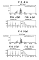
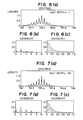
- Figs. 2(a) to 2(c) to Fig. 9(a) to 9(c) are graphs of simulation in which variations in the coherency function of a multi-mode laser having a reference wavelength of λ₀ = 780 nm and a mode interval of P = 0.3 nm were obtained when parameters Δλ, H and h were changed. All the results shown in the graphs were obtained by a Fourier transformation of the spectral function. In Figs. 2(a) to 2(c) and all subsequent figures, figures denoted (a) illustrate the spectral function, figures denoted (b) illustrate the coherency function, and figures denoted (c) illustrate enlargement of the coherency function of corresponding figures denoted (b) in the vicinity of zero. The unit of measure of the abscissa of figures denoted (a) is [nm], and the unit of the abscissa of figures denoted (b) and (c) is [mm]. The abscissas of (b) and (c) represent optical path differences, and the ordinates of (b) and (c) represent coherency.
- Referring to Figs. 2(a) to 2(c), to 5(a) to 5(c), the coherency function was obtained by assuming a Gaussian type of spectral function of respective modes and changing the half width Δλ within a range of 0.1 to 0.01 nm. Referring to Figs. 6(a) to 6(c), to 9 (a) to 9(c), the coherency function was obtained by assuming a Lorentz type of spectral function of respective modes and changing the half width Δλ within a range of 0.1 to 0.01 nm. As is apparent from these graphs, there are a plurality of peaks in the coherency function of the multi-mode semiconductor laser having a plurality of discrete oscillation modes (vertical modes). The smaller the half width Δλ of each mode, the larger the number of peaks. If the environmental temperature changes during use of an encoder utilizing interference of diffracted light beams, the reference wavelength λ₀ changes. Changes in the phase of the interference signal and, hence, measurement errors due to changes in the reference wavelength can be reduced if the difference between the optical path lengths of the two beams is very small or '0'.
- If the interferometer is adjusted in such a manner that the interference intensity is maximized when the optical path lengths of the two beams are not equal to each other, measurement errors are increased, because a plurality of peaks appear in the coherency function. As a consequence, by using a multi-mode semiconductor laser having vertical modes with a predetermined half width Δλ, it is possible to limit high-order peaks and eliminate obscurity in adjustment for equalizing the optical path lengths. The condition therefor can be expressed as Δλ ≧ 0.03 nm as represented by equation (3).
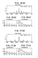
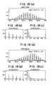
- Referring to Figs. 10 (a) to (c) to Figs. 13 (a) to 13(c), the coherency function was obtained by assuming that the envelop over the oscillation spectrum can be represented by a Gaussian function (H/h = const) and by changing the number of modes with an intensity ratio of 0.05 or higher within the envelop from 40 to 50. Referring to Figs. 14 (a) to (c) to Figs. 17 (a) to 13(c), the coherency function was obtained by assuming that the envelop over the oscillation spectrum can be represented by a Lorentz function (H/h = const) and by changing the width h of the envelop at an intensity ratio of 0.05 or higher from 12 to 1.5 nm. In can be understood that in either case the coherency abruptly decreases if the spread of the envelop increases. The width h and the coherence length are generally inversely proportional to each other. In a region where the optical path difference is close to zero, the coherency does not depend upon the types of the functions representing the envelop. In consequence, the width h obtained for setting the coherence length to 100 µm or more is equal to or smaller than 6 nm, as represented by equation (2).
- Referring to Figs. 18 (a) to (c) to Figs. 20 (a) to 20(c), the coherency function was obtained by shifting the reference wavelength λ₀ while constantly maintaining the width h of the envelop over the spectrum at an intensity ratio of 0.05 or higher so as to change the shape of the envelop. It can be clearly understood that the shape of the envelop of the spectrum does not substantially influence the coherency for an optical path length of a range of 0 to 0.1.
- To obtain the semiconductor laser satisfying the conditions defined by equations (1) to (3), it is necessary to select the type of semiconductor laser, the driving current, the reference environmental temperature, and so on, as desired. The above-described effects can be achieved by employing a semiconductor laser satisfying those conditions as the light source of the interferometer.
- In the encoder shown in Fig. 1B, the optical system is constructed in such a manner that the optical path lengths of a pair of diffracted light beams generated at the positions M₁ and M₂ and made to interfere with each other are substantially equal to each other. The driving current (signal) of the driving
current source 20 for driving thesemiconductor laser 1 can be changed, and a predetermined current (signal) is applied to thesemiconductor laser 1 so that the oscillation spectrum of thesemiconductor laser 1 satisfies the above-described conditions defined byequations 1 to 3. The present invention is therefore effective in that even if an optical path difference is produced by thermal expansion of the frame of the interferometer, the resulting reduction in the signal amplitude is very small and the occurrence of a discontinuity of the signal phase can be avoided. - The embodiment illustrated in Figs. 1A and 1B relates a rotary encoder, but the present invention can also be applied to linear encoders. Also, the present invention can be applied to various types of optical measurement apparatus using lasers other than encoders.
- An interferometer for measuring the displacement of a diffraction grating includes a multi-mode semiconductor laser for generating a laser beam; a device for supplying a predetermined current to the laser so that at least five vertical modes occur in an oscillation spectrum of the laser beam generated by the laser at an intensity ratio of at least 0.05; and an optical system for splitting the laser beam generated by the laser into first and second beams. The optical system also directs the first and second beams to the diffraction grating and effects interference between a first diffracted light beam generated by the diffraction of the first beam at the diffraction grating and a second diffracted light beam generated by the diffraction of the second beam at the diffraction grating to produce an interference light beam. Also provided is a photoelectric convertor for converting the interference light beam into an electrical signal.
Claims (22)
a multi-mode semiconductor laser generating a laser beam having at least five vertical modes each having an intensity ratio of at least 0.05;
generation means for generating interference light from a laser beam generated by said laser; and
detection means for detecting the interference light.
supplying laser radiation with a laser operated to have a predetermined spectrum with at least five vertical modes each having an intensity ratio of at least 0.05;
forming an interference beam with the laser radiation; and
detecting the interference beam.
a multi-mode semiconductor laser generating a laser beam having at least five vertical modes each having an intensity ratio of at least 0.05;
interference means for directing the laser beam from said laser to the diffraction grating and causing first and second diffracted light beams generated at the diffraction grating to interfere with each other to generate an interference light beam; and
conversion means for converting the interference light supplied by said interference means into an electrical signal.
a multi-mode semiconductor laser for generating a laser beam;
supply means for supplying a predetermined current to said laser so that at least five vertical modes occur in an oscillation spectrum of the laser beam generated by said laser at an intensity ratio of at least 0.05;
interference means for splitting the laser beam generated by said laser into first and second beams, for directing the first and second beams to the diffraction grating, and for effecting interference between a first diffracted light beam generated by diffraction of the first beam at the diffraction grating and a second diffracted light beam generated by diffraction of the second beam at the diffraction grating to produce an interference light; and
conversion means for converting the interference light produced by said interference means into an electrical signal.
directing to the diffraction grating laser radiation with a laser operated to produce a predetermined spectrum having at least five vertical modes each having an intensity ratio of at least 0.05;
forming an interference beam from diffraction beams generated at the diffraction grating; and
converting the interference beam into an electrical signal.
providing a multi-mode semiconductor laser; and
supplying a predetermined current to said laser so as to emit the laser radiation from said laser.
Applications Claiming Priority (2)
| Application Number | Priority Date | Filing Date | Title |
|---|---|---|---|
| JP63264687A JP2547826B2 (en) | 1988-10-19 | 1988-10-19 | Interferometer using multimode semiconductor laser |
| JP264687/88 | 1988-10-19 |
Publications (3)
| Publication Number | Publication Date |
|---|---|
| EP0364984A2 true EP0364984A2 (en) | 1990-04-25 |
| EP0364984A3 EP0364984A3 (en) | 1990-06-13 |
| EP0364984B1 EP0364984B1 (en) | 1994-07-13 |
Family
ID=17406802
Family Applications (1)
| Application Number | Title | Priority Date | Filing Date |
|---|---|---|---|
| EP19890119346 Expired - Lifetime EP0364984B1 (en) | 1988-10-19 | 1989-10-18 | Interferometer using multi-mode semiconductor laser |
Country Status (3)
| Country | Link |
|---|---|
| EP (1) | EP0364984B1 (en) |
| JP (1) | JP2547826B2 (en) |
| DE (1) | DE68916742T2 (en) |
Cited By (4)
| Publication number | Priority date | Publication date | Assignee | Title |
|---|---|---|---|---|
| EP0577090A2 (en) * | 1992-06-30 | 1994-01-05 | Canon Kabushiki Kaisha | Optical encoder |
| DE4337005A1 (en) * | 1993-10-29 | 1995-05-04 | Heidenhain Gmbh Dr Johannes | Length and angle measuring device |
| US5442172A (en) * | 1994-05-27 | 1995-08-15 | International Business Machines Corporation | Wavefront reconstruction optics for use in a disk drive position measurement system |
| US5909333A (en) * | 1994-05-27 | 1999-06-01 | International Business Machines Corporation | Servo-writing system for use in a data recording disk drive |
Families Citing this family (5)
| Publication number | Priority date | Publication date | Assignee | Title |
|---|---|---|---|---|
| DE10235669B4 (en) * | 2002-08-03 | 2016-11-17 | Dr. Johannes Heidenhain Gmbh | Position measuring device |
| US8269945B2 (en) | 2007-12-28 | 2012-09-18 | Nikon Corporation | Movable body drive method and apparatus, exposure method and apparatus, pattern formation method and apparatus, and device manufacturing method |
| JP5724133B2 (en) * | 2011-01-25 | 2015-05-27 | 国立大学法人東京農工大学 | Structure measuring method and structure measuring apparatus |
| JP5695478B2 (en) * | 2011-04-15 | 2015-04-08 | Dmg森精機株式会社 | Optical displacement measuring device |
| JP6660315B2 (en) * | 2017-01-19 | 2020-03-11 | 日本電信電話株式会社 | 3D shape measuring device |
Citations (4)
| Publication number | Priority date | Publication date | Assignee | Title |
|---|---|---|---|---|
| GB1364563A (en) * | 1970-09-21 | 1974-08-21 | Holograf Corp | Interferometer |
| EP0065429A1 (en) * | 1981-04-16 | 1982-11-24 | Euromask | Method and apparatus for the optical measurement of displacement, and its application to step and repeat photoreproduction |
| EP0146244A2 (en) * | 1983-11-04 | 1985-06-26 | Sony Magnescale, Inc. | Optical instrument for measuring displacement |
| GB2187282A (en) * | 1986-02-28 | 1987-09-03 | Canon Kk | Rotary encoder |
Family Cites Families (2)
| Publication number | Priority date | Publication date | Assignee | Title |
|---|---|---|---|---|
| JPH0781884B2 (en) * | 1984-10-01 | 1995-09-06 | ソニーマグネスケール株式会社 | Optical displacement measuring device |
| JPH0640398B2 (en) * | 1985-05-20 | 1994-05-25 | パイオニア株式会社 | Optical pickup device |
-
1988
- 1988-10-19 JP JP63264687A patent/JP2547826B2/en not_active Expired - Lifetime
-
1989
- 1989-10-18 DE DE1989616742 patent/DE68916742T2/en not_active Expired - Fee Related
- 1989-10-18 EP EP19890119346 patent/EP0364984B1/en not_active Expired - Lifetime
Patent Citations (4)
| Publication number | Priority date | Publication date | Assignee | Title |
|---|---|---|---|---|
| GB1364563A (en) * | 1970-09-21 | 1974-08-21 | Holograf Corp | Interferometer |
| EP0065429A1 (en) * | 1981-04-16 | 1982-11-24 | Euromask | Method and apparatus for the optical measurement of displacement, and its application to step and repeat photoreproduction |
| EP0146244A2 (en) * | 1983-11-04 | 1985-06-26 | Sony Magnescale, Inc. | Optical instrument for measuring displacement |
| GB2187282A (en) * | 1986-02-28 | 1987-09-03 | Canon Kk | Rotary encoder |
Non-Patent Citations (1)
| Title |
|---|
| OPTICS LETTERS. vol. 13, no. 8, August 1988, pages 628-630, New York, US; W.-K. CHEN et al.: "Short-coherence-length and hihg-coupling-efficiency pulsed diode laser for fiber-optic sensors". * |
Cited By (7)
| Publication number | Priority date | Publication date | Assignee | Title |
|---|---|---|---|---|
| EP0577090A2 (en) * | 1992-06-30 | 1994-01-05 | Canon Kabushiki Kaisha | Optical encoder |
| EP0577090A3 (en) * | 1992-06-30 | 1994-03-23 | Canon Kk | |
| US5359193A (en) * | 1992-06-30 | 1994-10-25 | Canon Kabushiki Kaisha | Talbot's interference type optical encoder |
| DE4337005A1 (en) * | 1993-10-29 | 1995-05-04 | Heidenhain Gmbh Dr Johannes | Length and angle measuring device |
| DE4337005C2 (en) * | 1993-10-29 | 2000-11-02 | Heidenhain Gmbh Dr Johannes | Length or angle measuring device |
| US5442172A (en) * | 1994-05-27 | 1995-08-15 | International Business Machines Corporation | Wavefront reconstruction optics for use in a disk drive position measurement system |
| US5909333A (en) * | 1994-05-27 | 1999-06-01 | International Business Machines Corporation | Servo-writing system for use in a data recording disk drive |
Also Published As
| Publication number | Publication date |
|---|---|
| JPH02110319A (en) | 1990-04-23 |
| DE68916742D1 (en) | 1994-08-18 |
| JP2547826B2 (en) | 1996-10-23 |
| DE68916742T2 (en) | 1994-11-03 |
| EP0364984A3 (en) | 1990-06-13 |
| EP0364984B1 (en) | 1994-07-13 |
Similar Documents
| Publication | Publication Date | Title |
|---|---|---|
| US4676645A (en) | Optical instrument for measuring displacement | |
| JP2673086B2 (en) | Method and apparatus for interferometrically determining the phase difference between differently polarized light beams | |
| US4979826A (en) | Displacement measuring apparatus | |
| US4970388A (en) | Encoder with diffraction grating and multiply diffracted light | |
| EP0309281B1 (en) | Apparatus for controlling relation in position between a photomask and a wafer | |
| US5574560A (en) | Dual-beam interferometer with a phase grating | |
| US5483377A (en) | Displacement detection apparatus | |
| JPH0650813A (en) | Monochrometer and spectral method | |
| US5198873A (en) | Encoder utilizing interference using multi-mode semiconductor laser | |
| JPH0820275B2 (en) | Position measuring device | |
| EP0364984B1 (en) | Interferometer using multi-mode semiconductor laser | |
| US5828061A (en) | Apparatus for detecting a rotation angle of a diffraction grating | |
| US4975570A (en) | Rotary encoder using multiple diffracted beams having co-incident paths | |
| US20070109556A1 (en) | Methods and Apparatus for Reducing Error in Interferometric Imaging Measurements | |
| KR20000017081A (en) | Optical displacement measurement system | |
| JP2000081308A (en) | Optical type displacement measuring apparatus | |
| JPH04225117A (en) | Integrated optical sensor device | |
| US5182613A (en) | Position detecting apparatus generating periodic detection signals having equal third and fifth harmonic components | |
| US5067813A (en) | Optical apparatus for measuring displacement of an object | |
| JPH0342519A (en) | Diffraction-coding position measuring device | |
| US6940606B2 (en) | Non-etalon reflective wavelength locking optical sub-assembly and associated methods | |
| JPH0235248B2 (en) | ||
| JP2718440B2 (en) | Length measuring or angle measuring device | |
| JPH09166414A (en) | Light measuring device | |
| US4912320A (en) | Optical type encoder including diffraction grating for producing interference fringes that are processed to measure displacement |
Legal Events
| Date | Code | Title | Description |
|---|---|---|---|
| PUAI | Public reference made under article 153(3) epc to a published international application that has entered the european phase |
Free format text: ORIGINAL CODE: 0009012 |
|
| AK | Designated contracting states |
Kind code of ref document: A2 Designated state(s): DE FR GB NL |
|
| PUAL | Search report despatched |
Free format text: ORIGINAL CODE: 0009013 |
|
| AK | Designated contracting states |
Kind code of ref document: A3 Designated state(s): DE FR GB NL |
|
| 17P | Request for examination filed |
Effective date: 19901030 |
|
| 17Q | First examination report despatched |
Effective date: 19910704 |
|
| GRAA | (expected) grant |
Free format text: ORIGINAL CODE: 0009210 |
|
| AK | Designated contracting states |
Kind code of ref document: B1 Designated state(s): DE FR GB NL |
|
| REF | Corresponds to: |
Ref document number: 68916742 Country of ref document: DE Date of ref document: 19940818 |
|
| ET | Fr: translation filed | ||
| PLBE | No opposition filed within time limit |
Free format text: ORIGINAL CODE: 0009261 |
|
| STAA | Information on the status of an ep patent application or granted ep patent |
Free format text: STATUS: NO OPPOSITION FILED WITHIN TIME LIMIT |
|
| 26N | No opposition filed | ||
| REG | Reference to a national code |
Ref country code: GB Ref legal event code: IF02 |
|
| PGFP | Annual fee paid to national office [announced via postgrant information from national office to epo] |
Ref country code: NL Payment date: 20071015 Year of fee payment: 19 Ref country code: DE Payment date: 20071011 Year of fee payment: 19 |
|
| PGFP | Annual fee paid to national office [announced via postgrant information from national office to epo] |
Ref country code: FR Payment date: 20071009 Year of fee payment: 19 Ref country code: GB Payment date: 20071017 Year of fee payment: 19 |
|
| GBPC | Gb: european patent ceased through non-payment of renewal fee |
Effective date: 20081018 |
|
| NLV4 | Nl: lapsed or anulled due to non-payment of the annual fee |
Effective date: 20090501 |
|
| REG | Reference to a national code |
Ref country code: FR Ref legal event code: ST Effective date: 20090630 |
|
| PG25 | Lapsed in a contracting state [announced via postgrant information from national office to epo] |
Ref country code: NL Free format text: LAPSE BECAUSE OF NON-PAYMENT OF DUE FEES Effective date: 20090501 |
|
| PG25 | Lapsed in a contracting state [announced via postgrant information from national office to epo] |
Ref country code: DE Free format text: LAPSE BECAUSE OF NON-PAYMENT OF DUE FEES Effective date: 20090501 |
|
| PG25 | Lapsed in a contracting state [announced via postgrant information from national office to epo] |
Ref country code: FR Free format text: LAPSE BECAUSE OF NON-PAYMENT OF DUE FEES Effective date: 20081031 |
|
| PG25 | Lapsed in a contracting state [announced via postgrant information from national office to epo] |
Ref country code: GB Free format text: LAPSE BECAUSE OF NON-PAYMENT OF DUE FEES Effective date: 20081018 |