EP0364716B1 - Digitally controlled lathe - Google Patents
Digitally controlled lathe Download PDFInfo
- Publication number
- EP0364716B1 EP0364716B1 EP89116344A EP89116344A EP0364716B1 EP 0364716 B1 EP0364716 B1 EP 0364716B1 EP 89116344 A EP89116344 A EP 89116344A EP 89116344 A EP89116344 A EP 89116344A EP 0364716 B1 EP0364716 B1 EP 0364716B1
- Authority
- EP
- European Patent Office
- Prior art keywords
- tool
- measuring
- cross slide
- slide
- cross
- Prior art date
- Legal status (The legal status is an assumption and is not a legal conclusion. Google has not performed a legal analysis and makes no representation as to the accuracy of the status listed.)
- Expired - Lifetime
Links
Images


Classifications
-
- G—PHYSICS
- G05—CONTROLLING; REGULATING
- G05B—CONTROL OR REGULATING SYSTEMS IN GENERAL; FUNCTIONAL ELEMENTS OF SUCH SYSTEMS; MONITORING OR TESTING ARRANGEMENTS FOR SUCH SYSTEMS OR ELEMENTS
- G05B19/00—Programme-control systems
- G05B19/02—Programme-control systems electric
- G05B19/18—Numerical control [NC], i.e. automatically operating machines, in particular machine tools, e.g. in a manufacturing environment, so as to execute positioning, movement or co-ordinated operations by means of programme data in numerical form
-
- B—PERFORMING OPERATIONS; TRANSPORTING
- B23—MACHINE TOOLS; METAL-WORKING NOT OTHERWISE PROVIDED FOR
- B23Q—DETAILS, COMPONENTS, OR ACCESSORIES FOR MACHINE TOOLS, e.g. ARRANGEMENTS FOR COPYING OR CONTROLLING; MACHINE TOOLS IN GENERAL CHARACTERISED BY THE CONSTRUCTION OF PARTICULAR DETAILS OR COMPONENTS; COMBINATIONS OR ASSOCIATIONS OF METAL-WORKING MACHINES, NOT DIRECTED TO A PARTICULAR RESULT
- B23Q17/00—Arrangements for observing, indicating or measuring on machine tools
- B23Q17/09—Arrangements for observing, indicating or measuring on machine tools for indicating or measuring cutting pressure or for determining cutting-tool condition, e.g. cutting ability, load on tool
-
- B—PERFORMING OPERATIONS; TRANSPORTING
- B23—MACHINE TOOLS; METAL-WORKING NOT OTHERWISE PROVIDED FOR
- B23Q—DETAILS, COMPONENTS, OR ACCESSORIES FOR MACHINE TOOLS, e.g. ARRANGEMENTS FOR COPYING OR CONTROLLING; MACHINE TOOLS IN GENERAL CHARACTERISED BY THE CONSTRUCTION OF PARTICULAR DETAILS OR COMPONENTS; COMBINATIONS OR ASSOCIATIONS OF METAL-WORKING MACHINES, NOT DIRECTED TO A PARTICULAR RESULT
- B23Q3/00—Devices holding, supporting, or positioning work or tools, of a kind normally removable from the machine
- B23Q3/155—Arrangements for automatic insertion or removal of tools, e.g. combined with manual handling
- B23Q3/15513—Arrangements for automatic insertion or removal of tools, e.g. combined with manual handling the tool being taken from a storage device and transferred to a tool holder by means of transfer devices
-
- G—PHYSICS
- G05—CONTROLLING; REGULATING
- G05B—CONTROL OR REGULATING SYSTEMS IN GENERAL; FUNCTIONAL ELEMENTS OF SUCH SYSTEMS; MONITORING OR TESTING ARRANGEMENTS FOR SUCH SYSTEMS OR ELEMENTS
- G05B2219/00—Program-control systems
- G05B2219/30—Nc systems
- G05B2219/49—Nc machine tool, till multiple
- G05B2219/49375—Minimalizing machine time, number of tool change
-
- G—PHYSICS
- G05—CONTROLLING; REGULATING
- G05B—CONTROL OR REGULATING SYSTEMS IN GENERAL; FUNCTIONAL ELEMENTS OF SUCH SYSTEMS; MONITORING OR TESTING ARRANGEMENTS FOR SUCH SYSTEMS OR ELEMENTS
- G05B2219/00—Program-control systems
- G05B2219/30—Nc systems
- G05B2219/50—Machine tool, machine tool null till machine tool work handling
- G05B2219/50291—Multi-tool, several tools
Definitions
- the invention relates to a numerically controlled lathe with a tool measuring device, a rotary support which can be displaced in the longitudinal feed direction and which contains a plan slide which can be displaced in the plan feed direction with a tool holder, with a tool magazine, a plurality of tools, a tool transport device and a probe of a measuring device, the probe of each tool missing on its cutting edge.
- Such a lathe has the disadvantage that the measurement of the cutting edge of a tool inevitably leads to an interruption in the machining of the workpiece. This is associated with an unfavorable degree of utilization of the lathe, since the measuring time is fully incorporated into the machining time.
- the invention has for its object to provide a lathe of the type mentioned in such a way that an interruption in workpiece machining is avoided while measuring the cutting edge of a tool.
- this object is achieved in that the tool magazine, the tool transport device, the probe and a cross slide provided with an additional tool holder are arranged on the cross slide for the automatic tool measurement during the workpiece machining, that the tool transport device for the transport of each tool between the tool magazine and the is designed both tool holders and that the measuring device contains the probe and the cross slide.
- Two motors are provided to drive the cross slide.
- the invention is based on a drawing in which an embodiment is shown schematically, described in more detail.
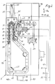
- a numerically controlled lathe 1 is composed of a machine bed 2, a headstock 3, a tailstock 4, a turning support 5 and a switching and control unit 6.
- the headstock 3 has a main spindle 7 with a face plate 9.
- the rotary movement of the face plate 8 generates a motor 9 which drives the main spindle 7 via a belt (10) and a planetary gear 11.
- a workpiece 13 picked up by the face plate 8 and a center point 12 of the tailstock 4 is located on the lathe 1.
- the axis of rotation of the lathe 1 is designated 14.
- the rotary support 5 has a bed slide 16 which can be displaced on the machine bed 2 in the longitudinal feed direction (double arrow 15).
- the longitudinal feed movement of the bed slide 16 generates a motor 17.
- the bed slide 16 carries a face slide 18 which can be displaced in the direction of face advance (double arrow 17 a ).
- the plan feed movement of the cross slide 18 generates a motor 19.
- a tool carrier 20 with a tool holder 21 belongs to the cross slide 18.
- a tool magazine 22, a measuring device 23 and a tool transport device 24 are arranged on the cross slide 18.
- the tool magazine 22 is designed with a revolving chain 26 driven by a motor 25.
- the measuring device 23 contains a probe 27 and a cross slide 28.
- the cross slide 20 has a tool holder 29 which is designed like the tool holder 21 of the tool carrier 20.
- the measuring device 23 is used to measure each tool 30, 31, 32, 33, 34, 35, 36, 37, 38, 39, 40, 41, 42 on its cutting edge.
- the cross slide 28 is driven by two motors 43, 44.
- the tool transport device 24 is designed for the transport of each tool 30 to 42 in a triangular area 45, which is formed by the tool magazine 22 and the tool holders 21, 29.
- the motors 9, 17, 19, 25, 43, 44, the probe 27 and the tool transport device 24 are each connected via a line 46, 47, 48, 49, 50, 51, 52, 53 to the switching device fed by a power supply 54 and control unit 6 connected.
- the lathe 1 allows a measurement of the cutting edge of the tool 31 and a measurement value processing in the numerical control during a partial machining of the workpiece 13 with the tool 30.
- a gripper 55 of the tool transport device 24 successively transports the tool 30 from the tool holder 21 of the tool holder 20 to an empty support member 56 of the circulating chain 26 and the measured tool 31 from the tool holder 29 of the cross slide 28 to the tool holder 21 of the tool holder 20. Then a further partial machining of the workpiece 13 is carried out with the tool 31.
Landscapes
- Engineering & Computer Science (AREA)
- Mechanical Engineering (AREA)
- Physics & Mathematics (AREA)
- Manufacturing & Machinery (AREA)
- General Physics & Mathematics (AREA)
- Automation & Control Theory (AREA)
- Human Computer Interaction (AREA)
- Turning (AREA)
- Electrical Discharge Machining, Electrochemical Machining, And Combined Machining (AREA)
- Electrophonic Musical Instruments (AREA)
- Exchange Systems With Centralized Control (AREA)
- Liquid Crystal Substances (AREA)
- Iron Core Of Rotating Electric Machines (AREA)
Abstract
Description
Die Erfindung bezieht sich auf eine numerisch gesteuerte Drehmaschine mit einer Werkzeugmeßeinrichtung, einem in Längsvorschubrichtung verschiebbaren Drehsupport, der einen in Planvorschubrichtung verschiebbaren Planschlitten mit einer Werkzeugaufnahme enthält, mit einem Werkzeugmagazin, mehreren Werkzeugen, einer Werkzeugtransportvorrichtung und einem Meßtaster einer Meßvorrichtung, wobei der Meßtaster jedes Werkzeug an seiner Schneide vermißt.The invention relates to a numerically controlled lathe with a tool measuring device, a rotary support which can be displaced in the longitudinal feed direction and which contains a plan slide which can be displaced in the plan feed direction with a tool holder, with a tool magazine, a plurality of tools, a tool transport device and a probe of a measuring device, the probe of each tool missing on its cutting edge.
Bei einer aus der DE-Z tz für Metallbearbeitung, 79. Jahrg. 1985, Heft 7/85, S. 29, 30, 32 bis 35, bekannten Drehmaschine der vorgenannten Art wird ein von der Werkzeugaufnahme des Planschlittens aufgenommenes Werkzeug an seiner Schneide vermessen mit einem Meßtaster, der an dem Spindelstock befestigt ist.In a lathe of the aforementioned type known from DE-Z tz for metalworking, 79th year 1985, number 7/85,
Eine derartige Drehmaschine hat den Nachteil, daß die Vermessung der Schneide eines Werkzeuges zwangsläufig zu einer Unterbrechung der Werkstückbearbeitung führt. Hiermit verbunden ist ein ungünstiger Nutzungsgrad der Drehmaschine, da die Meßzeit voll in die Bearbeitungszeit eingeht.Such a lathe has the disadvantage that the measurement of the cutting edge of a tool inevitably leads to an interruption in the machining of the workpiece. This is associated with an unfavorable degree of utilization of the lathe, since the measuring time is fully incorporated into the machining time.
Der Erfindung liegt die Aufgabe zugrunde, eine Drehmaschine der eingangs genannten Art so auszubilden, daß eine Unterbrechung der Werkstückbearbeitung während der Vermessung der Schneide eines Werkzeuges vermieden wird.The invention has for its object to provide a lathe of the type mentioned in such a way that an interruption in workpiece machining is avoided while measuring the cutting edge of a tool.
Erfindungsgemäß wird diese Aufgabe dadurch gelöst, daß zur automatischen Werkzeugvermessung während der Werkstückbearbeitung das Werkzeugmagazin, die Werkzeugtransportvorrichtung, der Meßtaster und ein mit einer zusätzlichen Werkzeugaufnahme versehener Kreuzschlitten auf dem Planschlitten angeordnet sind, daß die Werkzeugtransportvorrichtung für den Transport eines jeden Werkzeugs zwischen dem Werkzeugmagazin und den beiden Werkzeugaufnahmen ausgelegt ist und daß die Meßvorrichtung den Meßtaster und den Kreuzschlitten enthält.According to the invention, this object is achieved in that the tool magazine, the tool transport device, the probe and a cross slide provided with an additional tool holder are arranged on the cross slide for the automatic tool measurement during the workpiece machining, that the tool transport device for the transport of each tool between the tool magazine and the is designed both tool holders and that the measuring device contains the probe and the cross slide.
Zum Antrieb des Kreuzschlittens sind zwei Motoren vorgesehen.Two motors are provided to drive the cross slide.
Im folgenden wird die Erfindung anhand einer Zeichnung, in der ein Ausführungsbeispiel schematisch dargestellt ist, näher beschrieben.The invention is based on a drawing in which an embodiment is shown schematically, described in more detail.
Es zeigt
- Fig. 1
- eine numerisch gesteuerte Drehmaschine mit einem Maschinenbett, einem Spindelstock, einem Reitstock, einem Drehsupport und einem von dem Spindel- und dem Reitstock aufgenommenen Werkstück im Grundriß,
- Fig. 2
- den Drehsupport mit einem Werkzeugmagazin, mehreren Werkzeugen, einer Meßvorrichtung und einer Werkzeugtransportvorrichtung im Grundriß in vergrößertem Maßstab,
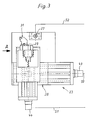
- Fig. 3
- die Meßvorrichtung im Grundriß in einem anderen vergrößerten Maßstab,
- Fig. 4
- eine Ansicht der Meßvorrichtung in Richtung des Pfeiles A in Fig. 3 in vergrößertem Maßstab.
- Fig. 1
- a numerically controlled lathe with a machine bed, a headstock, a tailstock, a turning support and a workpiece picked up by the headstock and the tailstock,
- Fig. 2
- the turning support with a tool magazine, several tools, a measuring device and a tool transport device in plan view on an enlarged scale,
- Fig. 3
- the measuring device in plan in another enlarged scale,
- Fig. 4
- a view of the measuring device in the direction of arrow A in Fig. 3 on an enlarged scale.
Eine numerisch gesteuerte Drehmaschine 1 setzt sich zusammen aus einem Maschinenbett 2, einem Spindelstock 3, einem Reitstock 4, einem Drehsupport 5 sowie einer Schalt- und Steuereinheit 6.A numerically controlled
Der Spindelstock 3 besitzt eine Hauptspindel 7 mit einer Planscheibe 9.The
Die Drehbewegung der Planscheibe 8 erzeugt ein Motor 9, der über ein Riemen- (10) und ein Planetengetriebe 11 die Hauptspindel 7 antreibt.The rotary movement of the
Auf der Drehmaschine 1 befindet sich ein von der Planscheibe 8 und einer Körnerspitze 12 des Reitstockes 4 aufgenommenes Werkstück 13.A
Die Drehachse der Drehmaschine 1 ist mit 14 bezeichnet.The axis of rotation of the
Der Drehsupport 5 weist einen auf dem Maschinenbett 2 in Längsvorschubrichtung (Doppelpfeil 15) verschiebbaren Bettschlitten 16 auf.The
Die Längsvorschubbewegung des Bettschlittens 16 erzeugt ein Motor 17.The longitudinal feed movement of the
Der Bettschlitten 16 trägt einen in Planvorschubrichtung (Doppelpfeil 17a) verschiebbaren Planschlitten 18.The
Die Planvorschubbewegung des Planschlittens 18 erzeugt ein Motor 19.The plan feed movement of the
Zu dem Planschlitten 18 gehört ein Werkzeugträger 20 mit einer Werkzeugaufnahme 21.A
Auf dem Planschlitten 18 sind ein Werkzeugmagazin 22, eine Meßvorrichtung 23 und eine Werkzeugtransportvorrichtung 24 angeordnet.A
Das Werkzeugmagazin 22 ist ausgeführt mit einer von einem Motor 25 angetriebenen Umlaufkette 26.The
Die Meßvorrichtung 23 enthält einen Meßtaster 27 und einen Kreuzschlitten 28.The
Der Kreuzschlitten 20 hat eine Werkzeugaufnahme 29, die wie die Werkzeugaufnahme 21 des Werkzeugträgers 20 ausgebildet ist.The
Die Meßvorrichtung 23 dient der Vermessung eines jeden Werkzeuges 30, 31, 32, 33, 34, 35, 36, 37, 38, 39, 40, 41, 42 an seiner Schneide.The
Angetrieben wird der Kreuzschlitten 28 von zwei Motoren 43, 44.The
Die Werkzeugtransportvorrichtung 24 ist ausgelegt für den Transport eines jeden Werkzeuges 30 bis 42 in einem Dreiecksbereich 45, der von dem Werkzeugmagazin 22 und den Werkzeugaufnahmen 21, 29 gebildet wird.The
Die Motoren 9, 17, 19, 25, 43, 44, der Meßtaster 27 und die Werkzeugtransportvorrichtung 24 sind über je eine Leitung 46, 47, 48, 49, 50, 51, 52, 53 an die von einem Stromnetz 54 gespeiste Schalt- und Steuereinheit 6 angeschlossen.The
Die Drehmaschine 1 erlaubt während einer Teilbearbeitung des Werkstückes 13 mit dem Werkzeug 30 eine Vermessung der Schneide des Werkzeuges 31 und eine Meßwertverarbeitung in der numerischen Steuerung.The
Sobald diese Teilbearbeitung abgeschlossen ist, transportiert ein Greifer 55 der Werkzeugtransportvorrichtung 24 nacheinander das Werkzeug 30 aus der Werkzeugaufnahme 21 des Werkzeugträgers 20 zu einem leeren Tragglied 56 der Umlaufkette 26 und das vermessene Werkzeug 31 von der Werkzeugaufnahme 29 des Kreuzschlittens 28 zu der Werkzeugaufnahme 21 des Werkzeugträgers 20. Danach wird eine weitere Teilbearbeitung des Werkstückes 13 mit dem Werkzeug 31 durchgeführt.As soon as this partial machining has been completed, a
Claims (2)
- Numerically controlled lathe having a tool measuring device, a lathe support rest (5) which is displaceable in the longitudinal feed direction (15) and which comprises a cross-slide rest (18) which is displaceable in the transverse feed direction (17a) and which has a tool receiving device (21), and a tool storage device (22), a plurality of tools (30 to 42), a tool transportation device (24) and a measuring calliper (27) of a measuring device (23), wherein the measuring calliper (27) measures each tool (30 to 42) on its cutter, characterised in that in order to automate the taking of the measurement of the tool during the finishing work on the workpiece, the tool storage device (22), the tool transportation device (24), the measuring calliper (27) and a cross slide (28) provided with an additional tool receiving device (29) are arranged on the cross-slide rest (18), further that the tool transportation device (24) is designed for transporting one of the tools (30 to 42) between the tool storage device (22) and the two tool receiving devices (21, 29) and further the measuring device (23) comprises the measuring calliper (27) and the cross slide (28).
- A numerically controlled lathe according to claim 1, characterised in that two motors (43,44) are provided for the purpose of driving the cross slide (28).
Priority Applications (1)
| Application Number | Priority Date | Filing Date | Title |
|---|---|---|---|
| AT89116344T ATE87525T1 (en) | 1988-10-21 | 1989-09-05 | NUMERICALLY CONTROLLED LATHE. |
Applications Claiming Priority (2)
| Application Number | Priority Date | Filing Date | Title |
|---|---|---|---|
| DE3835830A DE3835830C1 (en) | 1988-10-21 | 1988-10-21 | |
| DE3835830 | 1988-10-21 |
Publications (3)
| Publication Number | Publication Date |
|---|---|
| EP0364716A2 EP0364716A2 (en) | 1990-04-25 |
| EP0364716A3 EP0364716A3 (en) | 1991-03-20 |
| EP0364716B1 true EP0364716B1 (en) | 1993-03-31 |
Family
ID=6365590
Family Applications (1)
| Application Number | Title | Priority Date | Filing Date |
|---|---|---|---|
| EP89116344A Expired - Lifetime EP0364716B1 (en) | 1988-10-21 | 1989-09-05 | Digitally controlled lathe |
Country Status (5)
| Country | Link |
|---|---|
| EP (1) | EP0364716B1 (en) |
| AT (1) | ATE87525T1 (en) |
| DE (2) | DE3835830C1 (en) |
| ES (1) | ES2016234T3 (en) |
| GR (1) | GR900300152T1 (en) |
Families Citing this family (3)
| Publication number | Priority date | Publication date | Assignee | Title |
|---|---|---|---|---|
| JP2853755B2 (en) | 1992-12-02 | 1999-02-03 | 三菱電機株式会社 | Numerical control processing equipment |
| DE4406272C2 (en) * | 1994-02-25 | 1997-02-27 | Boehringer Werkzeugmaschinen | Machine tool for turning broaching, turning-turning broaching or turning and method for machining rotationally symmetrical workpieces |
| CN104259492B (en) * | 2014-09-22 | 2016-09-21 | 扬州力创机床有限公司 | A kind of lathe carriage |
Family Cites Families (4)
| Publication number | Priority date | Publication date | Assignee | Title |
|---|---|---|---|---|
| GB1195632A (en) * | 1968-01-25 | 1970-06-17 | Vero Prec Engineering Ltd | Improvements in Numerically Controlled Machine Tools |
| DE3216892A1 (en) * | 1982-05-06 | 1983-11-10 | Index-Werke Kg Hahn & Tessky, 7300 Esslingen | MULTI-SPINDLE REVOLVER TURNING MACHINE |
| JPS6234741A (en) * | 1985-08-06 | 1987-02-14 | Mazda Motor Corp | Tool replacing device in machining center |
| FR2599654B1 (en) * | 1986-06-06 | 1988-09-09 | Bucaille Bernard | MACHINING CENTER |
-
1988
- 1988-10-21 DE DE3835830A patent/DE3835830C1/de not_active Expired
-
1989
- 1989-09-05 ES ES198989116344T patent/ES2016234T3/en not_active Expired - Lifetime
- 1989-09-05 DE DE8989116344T patent/DE58903951D1/en not_active Expired - Fee Related
- 1989-09-05 EP EP89116344A patent/EP0364716B1/en not_active Expired - Lifetime
- 1989-09-05 AT AT89116344T patent/ATE87525T1/en not_active IP Right Cessation
-
1991
- 1991-09-27 GR GR90300152T patent/GR900300152T1/en unknown
Also Published As
| Publication number | Publication date |
|---|---|
| ES2016234A4 (en) | 1990-11-01 |
| EP0364716A3 (en) | 1991-03-20 |
| EP0364716A2 (en) | 1990-04-25 |
| ATE87525T1 (en) | 1993-04-15 |
| DE3835830C1 (en) | 1989-11-30 |
| GR900300152T1 (en) | 1991-09-27 |
| DE58903951D1 (en) | 1993-05-06 |
| ES2016234T3 (en) | 1993-10-01 |
Similar Documents
| Publication | Publication Date | Title |
|---|---|---|
| DE3416660C2 (en) | ||
| DE19521846B4 (en) | Numerically controlled processing machine | |
| DE19533320C2 (en) | Rotary transfer machine | |
| CH665586A5 (en) | MACHINE TOOL. | |
| DE2944540A1 (en) | TOOL CHANGING DEVICE FOR MACHINE TOOLS | |
| DE2033026C3 (en) | NC-controlled machining center for workpieces to be machined by turning from both sides as well as by milling and / or drilling | |
| DE2739534C2 (en) | Tool changing device | |
| DE9321647U1 (en) | Machining cell composed of assemblies | |
| US4454645A (en) | Multiple station drilling apparatus | |
| DE2760477C2 (en) | Method for grinding a flat surface and an adjoining cylindrical longitudinal surface of a workpiece | |
| DE3420531C2 (en) | Automatic lathe | |
| DE2427148A1 (en) | LATHE | |
| EP0185011B1 (en) | Tool holder | |
| DE3824602A1 (en) | Machine for machining cubic and rotationally symmetric workpieces | |
| DE10307977C5 (en) | Method and device for processing differential housings | |
| DE3320598C2 (en) | Machine tool with a device for removing machining residues | |
| EP0364716B1 (en) | Digitally controlled lathe | |
| DE2804584A1 (en) | Machine tool with multiple working stations - has fixed and retractable machining units at stations connected to common power unit | |
| DE1502031B2 (en) | Multi-spindle automatic lathe | |
| DE1945595A1 (en) | Machine complex | |
| DE3202723A1 (en) | Machine tool for machining spherical workpieces of large dimensions | |
| EP0410044B1 (en) | Lathe with three spindles for workpieces | |
| DE3529481A1 (en) | Machine for the static and rotary machining of workpieces | |
| DE3530982A1 (en) | Two-spindle numerically controlled lathe | |
| EP1285725B1 (en) | Lathe for the machining on all sides and systematic placement of workpieces |
Legal Events
| Date | Code | Title | Description |
|---|---|---|---|
| PUAI | Public reference made under article 153(3) epc to a published international application that has entered the european phase |
Free format text: ORIGINAL CODE: 0009012 |
|
| AK | Designated contracting states |
Kind code of ref document: A2 Designated state(s): AT BE CH DE ES FR GB GR IT LI LU NL SE |
|
| ITCL | It: translation for ep claims filed |
Representative=s name: RICCARDI SERGIO & CO. |
|
| EL | Fr: translation of claims filed | ||
| TCNL | Nl: translation of patent claims filed | ||
| GBC | Gb: translation of claims filed (gb section 78(7)/1977) | ||
| PUAL | Search report despatched |
Free format text: ORIGINAL CODE: 0009013 |
|
| AK | Designated contracting states |
Kind code of ref document: A3 Designated state(s): AT BE CH DE ES FR GB GR IT LI LU NL SE |
|
| RHK1 | Main classification (correction) |
Ipc: B23Q 3/155 |
|
| 17P | Request for examination filed |
Effective date: 19910426 |
|
| 17Q | First examination report despatched |
Effective date: 19920127 |
|
| GRAA | (expected) grant |
Free format text: ORIGINAL CODE: 0009210 |
|
| AK | Designated contracting states |
Kind code of ref document: B1 Designated state(s): AT BE CH DE ES FR GB GR IT LI LU NL SE |
|
| PG25 | Lapsed in a contracting state [announced via postgrant information from national office to epo] |
Ref country code: GR Free format text: LAPSE BECAUSE OF FAILURE TO SUBMIT A TRANSLATION OF THE DESCRIPTION OR TO PAY THE FEE WITHIN THE PRESCRIBED TIME-LIMIT Effective date: 19930331 |
|
| REF | Corresponds to: |
Ref document number: 87525 Country of ref document: AT Date of ref document: 19930415 Kind code of ref document: T |
|
| REF | Corresponds to: |
Ref document number: 58903951 Country of ref document: DE Date of ref document: 19930506 |
|
| GBT | Gb: translation of ep patent filed (gb section 77(6)(a)/1977) |
Effective date: 19930414 |
|
| ET | Fr: translation filed | ||
| ITF | It: translation for a ep patent filed |
Owner name: UFFICIO BREVETTI RICCARDI & C. |
|
| REG | Reference to a national code |
Ref country code: GR Ref legal event code: FG4A Free format text: 3008015 |
|
| PG25 | Lapsed in a contracting state [announced via postgrant information from national office to epo] |
Ref country code: AT Effective date: 19930905 |
|
| PG25 | Lapsed in a contracting state [announced via postgrant information from national office to epo] |
Ref country code: SE Effective date: 19930906 |
|
| PG25 | Lapsed in a contracting state [announced via postgrant information from national office to epo] |
Ref country code: LU Free format text: LAPSE BECAUSE OF NON-PAYMENT OF DUE FEES Effective date: 19930930 |
|
| REG | Reference to a national code |
Ref country code: ES Ref legal event code: FG2A Ref document number: 2016234 Country of ref document: ES Kind code of ref document: T3 |
|
| PLBE | No opposition filed within time limit |
Free format text: ORIGINAL CODE: 0009261 |
|
| STAA | Information on the status of an ep patent application or granted ep patent |
Free format text: STATUS: NO OPPOSITION FILED WITHIN TIME LIMIT |
|
| 26N | No opposition filed | ||
| PG25 | Lapsed in a contracting state [announced via postgrant information from national office to epo] |
Ref country code: NL Effective date: 19940401 |
|
| NLV4 | Nl: lapsed or anulled due to non-payment of the annual fee | ||
| PGFP | Annual fee paid to national office [announced via postgrant information from national office to epo] |
Ref country code: GB Payment date: 19940815 Year of fee payment: 6 Ref country code: CH Payment date: 19940815 Year of fee payment: 6 |
|
| PGFP | Annual fee paid to national office [announced via postgrant information from national office to epo] |
Ref country code: FR Payment date: 19940819 Year of fee payment: 6 |
|
| PGFP | Annual fee paid to national office [announced via postgrant information from national office to epo] |
Ref country code: BE Payment date: 19940825 Year of fee payment: 6 |
|
| PGFP | Annual fee paid to national office [announced via postgrant information from national office to epo] |
Ref country code: ES Payment date: 19940915 Year of fee payment: 6 |
|
| REG | Reference to a national code |
Ref country code: GR Ref legal event code: MM2A Free format text: 3008015 |
|
| EUG | Se: european patent has lapsed |
Ref document number: 89116344.6 Effective date: 19940410 |
|
| PGFP | Annual fee paid to national office [announced via postgrant information from national office to epo] |
Ref country code: DE Payment date: 19950825 Year of fee payment: 7 |
|
| PG25 | Lapsed in a contracting state [announced via postgrant information from national office to epo] |
Ref country code: GB Effective date: 19950905 |
|
| PG25 | Lapsed in a contracting state [announced via postgrant information from national office to epo] |
Ref country code: ES Free format text: LAPSE BECAUSE OF EXPIRATION OF PROTECTION Effective date: 19950906 |
|
| PG25 | Lapsed in a contracting state [announced via postgrant information from national office to epo] |
Ref country code: LI Effective date: 19950930 Ref country code: CH Effective date: 19950930 Ref country code: BE Effective date: 19950930 |
|
| BERE | Be: lapsed |
Owner name: HOESCH MASCHINENFABRIK DEUTSCHLAND A.G. Effective date: 19950930 |
|
| GBPC | Gb: european patent ceased through non-payment of renewal fee |
Effective date: 19950905 |
|
| REG | Reference to a national code |
Ref country code: CH Ref legal event code: PL |
|
| PG25 | Lapsed in a contracting state [announced via postgrant information from national office to epo] |
Ref country code: FR Effective date: 19960531 |
|
| REG | Reference to a national code |
Ref country code: FR Ref legal event code: ST |
|
| PG25 | Lapsed in a contracting state [announced via postgrant information from national office to epo] |
Ref country code: DE Effective date: 19970603 |
|
| REG | Reference to a national code |
Ref country code: ES Ref legal event code: FD2A Effective date: 19990601 |
|
| PG25 | Lapsed in a contracting state [announced via postgrant information from national office to epo] |
Ref country code: IT Free format text: LAPSE BECAUSE OF NON-PAYMENT OF DUE FEES;WARNING: LAPSES OF ITALIAN PATENTS WITH EFFECTIVE DATE BEFORE 2007 MAY HAVE OCCURRED AT ANY TIME BEFORE 2007. THE CORRECT EFFECTIVE DATE MAY BE DIFFERENT FROM THE ONE RECORDED. Effective date: 20050905 |