EP0364206A1 - Post-mix beverage dispenser unit - Google Patents
Post-mix beverage dispenser unit Download PDFInfo
- Publication number
- EP0364206A1 EP0364206A1 EP89310336A EP89310336A EP0364206A1 EP 0364206 A1 EP0364206 A1 EP 0364206A1 EP 89310336 A EP89310336 A EP 89310336A EP 89310336 A EP89310336 A EP 89310336A EP 0364206 A1 EP0364206 A1 EP 0364206A1
- Authority
- EP
- European Patent Office
- Prior art keywords
- syrup
- carbonator
- post
- valve
- pipe
- Prior art date
- Legal status (The legal status is an assumption and is not a legal conclusion. Google has not performed a legal analysis and makes no representation as to the accuracy of the status listed.)
- Granted
Links
Images

Classifications
-
- B—PERFORMING OPERATIONS; TRANSPORTING
- B67—OPENING, CLOSING OR CLEANING BOTTLES, JARS OR SIMILAR CONTAINERS; LIQUID HANDLING
- B67D—DISPENSING, DELIVERING OR TRANSFERRING LIQUIDS, NOT OTHERWISE PROVIDED FOR
- B67D7/00—Apparatus or devices for transferring liquids from bulk storage containers or reservoirs into vehicles or into portable containers, e.g. for retail sale purposes
- B67D7/06—Details or accessories
-
- B—PERFORMING OPERATIONS; TRANSPORTING
- B67—OPENING, CLOSING OR CLEANING BOTTLES, JARS OR SIMILAR CONTAINERS; LIQUID HANDLING
- B67D—DISPENSING, DELIVERING OR TRANSFERRING LIQUIDS, NOT OTHERWISE PROVIDED FOR
- B67D1/00—Apparatus or devices for dispensing beverages on draught
- B67D1/0042—Details of specific parts of the dispensers
- B67D1/0057—Carbonators
- B67D1/0069—Details
- B67D1/0074—Automatic carbonation control
-
- B—PERFORMING OPERATIONS; TRANSPORTING
- B67—OPENING, CLOSING OR CLEANING BOTTLES, JARS OR SIMILAR CONTAINERS; LIQUID HANDLING
- B67D—DISPENSING, DELIVERING OR TRANSFERRING LIQUIDS, NOT OTHERWISE PROVIDED FOR
- B67D1/00—Apparatus or devices for dispensing beverages on draught
- B67D1/0015—Apparatus or devices for dispensing beverages on draught the beverage being prepared by mixing at least two liquid components
- B67D1/0021—Apparatus or devices for dispensing beverages on draught the beverage being prepared by mixing at least two liquid components the components being mixed at the time of dispensing, i.e. post-mix dispensers
-
- B—PERFORMING OPERATIONS; TRANSPORTING
- B67—OPENING, CLOSING OR CLEANING BOTTLES, JARS OR SIMILAR CONTAINERS; LIQUID HANDLING
- B67D—DISPENSING, DELIVERING OR TRANSFERRING LIQUIDS, NOT OTHERWISE PROVIDED FOR
- B67D1/00—Apparatus or devices for dispensing beverages on draught
- B67D1/0042—Details of specific parts of the dispensers
- B67D1/0057—Carbonators
- B67D1/0061—Carbonators with cooling means
- B67D1/0066—Carbonators with cooling means outside the carbonator
- B67D1/0068—Cooling bath
-
- B—PERFORMING OPERATIONS; TRANSPORTING
- B67—OPENING, CLOSING OR CLEANING BOTTLES, JARS OR SIMILAR CONTAINERS; LIQUID HANDLING
- B67D—DISPENSING, DELIVERING OR TRANSFERRING LIQUIDS, NOT OTHERWISE PROVIDED FOR
- B67D1/00—Apparatus or devices for dispensing beverages on draught
- B67D1/08—Details
-
- B—PERFORMING OPERATIONS; TRANSPORTING
- B67—OPENING, CLOSING OR CLEANING BOTTLES, JARS OR SIMILAR CONTAINERS; LIQUID HANDLING
- B67D—DISPENSING, DELIVERING OR TRANSFERRING LIQUIDS, NOT OTHERWISE PROVIDED FOR
- B67D1/00—Apparatus or devices for dispensing beverages on draught
- B67D1/08—Details
- B67D1/0801—Details of beverage containers, e.g. casks, kegs
- B67D2001/0812—Bottles, cartridges or similar containers
-
- B—PERFORMING OPERATIONS; TRANSPORTING
- B67—OPENING, CLOSING OR CLEANING BOTTLES, JARS OR SIMILAR CONTAINERS; LIQUID HANDLING
- B67D—DISPENSING, DELIVERING OR TRANSFERRING LIQUIDS, NOT OTHERWISE PROVIDED FOR
- B67D2210/00—Indexing scheme relating to aspects and details of apparatus or devices for dispensing beverages on draught or for controlling flow of liquids under gravity from storage containers for dispensing purposes
- B67D2210/00028—Constructional details
- B67D2210/00031—Housing
-
- B—PERFORMING OPERATIONS; TRANSPORTING
- B67—OPENING, CLOSING OR CLEANING BOTTLES, JARS OR SIMILAR CONTAINERS; LIQUID HANDLING
- B67D—DISPENSING, DELIVERING OR TRANSFERRING LIQUIDS, NOT OTHERWISE PROVIDED FOR
- B67D2210/00—Indexing scheme relating to aspects and details of apparatus or devices for dispensing beverages on draught or for controlling flow of liquids under gravity from storage containers for dispensing purposes
- B67D2210/00146—Component storage means
- B67D2210/00149—Fixed containers to be filled in situ
Definitions
- the present invention relates to compact post-mix beverage dispensers which are portable and suitable for use in small offices or small dispensing volume locations, and more particularly, to a control device for controlling opening and closing operation of an electromagnetic valve which is disposed on a conduit connected between a CO2 cylinder and a syrup package.
- a post-mix beverage dispenser generally includes a syrup package having a flow control tube therein which is vented to the atmosphere, as shown in U.S. Patent No. 4,493,441 which is incorporated by reference.
- a hermetic package as a syrup package and to use the pressure of the CO2 from a CO2 cylinder to vent the syrup, as shown in EP-A-336730 (to be published on 11-10-89).
- the invention provides a post-mix dispensing system comprising an openable housing; compressed gas supply means; syrup dispensing means located generally within the housing and comprising a syrup reservoir having a syrup dispensing outlet and a compressed gas inlet for passing compressed gas from the gas supply means to the interior of the reservoir to facilitate or urge dispensing of syrup from it; and valve means for controlling passage of gas from the gas supply means to the gas inlet; characterised in that means are provided for detecting when said openable housing is open and actuating said valve means in response thereto to prevent said passage of gas.
- a preferred type of embodiment includes a cabinet housing which has at least a first access panel and a second access panel next thereto.
- a portable tank for storing potable water is detachable from the cabinet housing.
- a carbonator produces carbonated water by mixing cooled water from the portable tank with CO2.
- a cooling reservoir cools potable water which is supplied from the portable tank to the carbonator.
- the CO2 tank supplies CO2 to the carbonator.
- the syrup package dispenses a selected syrup.
- a first pipe is partially disposed in the cooling reservoir for linking the portable tank with the carbonator.
- a second pipe links the CO2 tank with the carbonator.
- a valve controls the flow of carbonated water from the carbonator.
- a third pipe links the carbonator with the valve.
- a fourth pipe links the second pipe to the syrup packages for supplying CO2 from the CO2 tank to the syrup packages to supply syrup from the syrup package to the valve.
- a control valve is disposed on the fourth pipe to open and close the communication between the CO2 tank and the syrup package in accordance with detected signals from a detecting device arranged to detect whether the first and second access panels are in their open or closed configuration.
- FIGS 1-3 show a portable post-mix beverage dispenser unit in accordance with one embodiment of this invention.
- the unit includes a cabinet 20 having a front access panel 201, top access panel 202, right side access panel 203, left side access panel 204, rear side access panel 205, bottom access panel 206 and additional access panel 207.
- Front access panel 201 carries a permanent magnet 201a attached thereon adjacent the top access panel 202.
- the top access panel 202 includes reed switch 202a attached thereon adjacent the permanent magnet 201a on front access panel 201 so that reed switch 202a is turned on when front access panel 201 is located on cabinet 20.
- Permanent magnet 201a and reed switch 202a form a detecting device 60 to detect whether front access panel 201 is located on cabinet 20 or not.
- Pouring station 21 is located below front access panel 201 and includes a drain plate 211 for receiving cups and for draining liquid spilled from the cups through a plurality of slits.
- Dispensing portion 212 is located between panel 201 and pouring station 21 and includes valve levers 213 extending downwardly in front.
- a cooling reservoir 22 is disposed in one upper corner of cabinet 20 and is covered by an insulating material.
- a carbonator 23, part of a cooling pipe 24, an agitator 25, and an ice sensor 26 are all disposed within cooling reservoir 22. Reservoir 22 stores cool water which is used for cooling potable water introduced to carbonator 23 through cooling pipe 24.
- a portable tank 27 is removably disposed in an upper left side of cabinet 20 and is used to store and supply potable water, both to be carbonated and to be mixed directly with the syrup.
- Control box 28, CO2 cylinder or tank 29, and a plurality of syrup packages S1, S2 and S3 located above and connected to dispensing portion 212, are disposed in an upper part of cabinet 20.
- Pump 30, compressor 31 and condenser 54 are disposed in a lower part of cabinet 20.
- Portable tank 27 is linked to pump 30 through sealing coupler 32 and first conduit 33. Sealing coupler 32 connects one end of first conduit 33 to portable tank 27 such that first conduit 33 can be disconnected therefrom without leakage of water.
- First conduit 33 is further linked with pump 30, and on the other side of pump 30 is linked to cooling pipe 24.
- Cooling pipe 24 has a rectangular serpentine portion 241 disposed in cooling reservoir 22.
- the other end of cooling pipe 24 is linked to second conduit 34 and to third conduit 35 through three-way electromagnetic valve 36.
- Second conduit 34 has a check valve 37 and extends to the interior of carbonator 23 located in cooling reservoir 22.
- Third conduit 35 is divided into three sub-conduits 35a, 35b and 35c, each sub-conduit coupled with a respective valve V1, V2 or V3 through respective flow control valves 38 disposed in dispensing portion 212.
- CO2 cylinder 29 is linked to the interior of carbonator 23 through fourth conduit 39.
- Check valve 40 and reducing valve 41 including pressure gauge 411 are disposed in fourth conduit 39 between cylinder tank 29 and carbonator 23.
- Carbonated water is produced in carbonator 23 by mixing cooled water from portable tank 27 with CO2 from CO2 cylinder 29.
- a fifth conduit 42 is linked to fourth conduit 39 at a location between reducing valve 41 and check valve 40.
- Fifth conduit 42 includes a reducing valve 43 and an electromagnetic valve 44. After the location of electromagnetic valve 44, fifth conduit 42 splits into three subconduits 42a, 42b and 42c, each one having a respective check valve 45.
- Subconduits 42a, 42b and 42c are linked to syrup packages S1, S2 and S3 respectively, and are further linked with valves V1, V2 and V3 respectively through respective flow control valves 46.
- Reducing valve 43 reduces the pressure of CO2 within fifth conduit 42 to a level of about 0.4 Kg/Cm2.
- the carbonator 23 contains cooled carbonated water.
- a sixth conduit 47 extends from near the bottom of carbonator 23, and is divided into three subconduits 47a, 47b and 47c at the other end.
- Subconduits 47a, 47b and 47c are coupled with valves V1, V2 and V3 respectively, through respective flow control valves 48.
- Valves V1, V2 and V3 are connected at their other ends to nozzles 49, 50 and 51, respectively, to dispense mixed beverages into respective cups 52.
- Evaporator 53 is disposed along the outer surface of the inner wall of cooling reservoir 22, and cools the water in cooling reservoir 22.
- Evaporator 53 forms part of a refrigeration circuit also including at least compressor 31 and condenser 54 located externally of cooling reservoir 22 within cabinet 20. The water in reservoir 22 is cooled by evaporator 53 until it is at a temperature of about 0 o C.
- Electromagnetic valve 44 is connected to control device 60, and opens and closes communication of fifth conduit 42 between reducing valve 43 and check valve 45 in accordance with instruction from detecting device 60.
- a user places a cup on drain plate 211 below a selected one of nozzle 49, 50 or 51 corresponding to a selected beverage.
- the user then pushes one of valve levers 213 which corresponds to the selected nozzle, simultaneously operating pump 30 and three way electromagnetic valve 36.
- Pump 30 pumps water from portable tank 27 through first conduit 33 and into serpentine portion 241 of cooling pipe 24, where it is cooled by the cooling water in reservoir 22. Thereafter, the water flows through three-way electromagnetic valve 36 into carbonator 23 where it is mixed with CO2 from CO2 cylinder 29 to carbonate the water.
- Float switch 55 controls the volume of carbonated water in carbonator 23. If the level of carbonated water is below a predetermined level, pump 30 operated and more potable water is supplied to carbonator 23 along with CO2 to raise the level of carbonated water back to the predetermined level.
- the water supplied to carbonator 23 is in the form of mist.
- CO2 cylinder 29 and syrup packages S1, S2 and S3 are detachable, when the contents of the tank or a syrup package is exhausted, the tank or package is removed and replaced with a fresh supply.
- front access panel 201 is removed from cabinet 20.
- the permanent magnet 201a is therefore separated from the reed switch 202a attached on top access panel 202. Therefore, reed switch 202a is turned off, thereby to stop supplying solenoid 44a of electromagnetic valve 44 with electric current from power source 61, as shown in Figure 6.
- Electromagnetic valve 44 thus closes the communication betwen fifth conduit 42 and respective subconduits 42a, 42b and 42c.
- the supply of CO2 to respective syrup packages S1, S2 and S3 is stopped at electromagnetic valve 44. Therefore, even though one or more syrup packages S1, S2 and S3 are removed from corresponding subconduits 42a, 42b and 42c, the CO2 in CO2 cylinder 29 is prevented from venting to the atmosphere.
Abstract
Description
- The present invention relates to compact post-mix beverage dispensers which are portable and suitable for use in small offices or small dispensing volume locations, and more particularly, to a control device for controlling opening and closing operation of an electromagnetic valve which is disposed on a conduit connected between a CO₂ cylinder and a syrup package.
- A post-mix beverage dispenser generally includes a syrup package having a flow control tube therein which is vented to the atmosphere, as shown in U.S. Patent No. 4,493,441 which is incorporated by reference. However, since there are some problems with respect to sanitation and inconstant flow rate of syrup in the above dispenser, it has been proposed to use a hermetic package as a syrup package and to use the pressure of the CO₂ from a CO₂ cylinder to vent the syrup, as shown in EP-A-336730 (to be published on 11-10-89).
- However, when the package is replaced with another new one after syrup is exhausted, a valve has to be switched to quit venting the CO₂ by a manual operation.
- It would therefore be desirable to provide a portable post-mix dispenser unit of which a syrup bottle can be easily replaced.
- The invention provides a post-mix dispensing system comprising an openable housing; compressed gas supply means; syrup dispensing means located generally within the housing and comprising a syrup reservoir having a syrup dispensing outlet and a compressed gas inlet for passing compressed gas from the gas supply means to the interior of the reservoir to facilitate or urge dispensing of syrup from it; and valve means for controlling passage of gas from the gas supply means to the gas inlet; characterised in that means are provided for detecting when said openable housing is open and actuating said valve means in response thereto to prevent said passage of gas.
- A preferred type of embodiment includes a cabinet housing which has at least a first access panel and a second access panel next thereto. A portable tank for storing potable water is detachable from the cabinet housing. A carbonator produces carbonated water by mixing cooled water from the portable tank with CO₂. A cooling reservoir cools potable water which is supplied from the portable tank to the carbonator. The CO₂ tank supplies CO₂ to the carbonator. The syrup package dispenses a selected syrup. A first pipe is partially disposed in the cooling reservoir for linking the portable tank with the carbonator. A second pipe links the CO₂ tank with the carbonator. A valve controls the flow of carbonated water from the carbonator. A third pipe links the carbonator with the valve. A fourth pipe links the second pipe to the syrup packages for supplying CO₂ from the CO₂ tank to the syrup packages to supply syrup from the syrup package to the valve. A control valve is disposed on the fourth pipe to open and close the communication between the CO₂ tank and the syrup package in accordance with detected signals from a detecting device arranged to detect whether the first and second access panels are in their open or closed configuration.
- An embodiment of the invention will be described in greater detail with reference to the accompanying drawings in which:
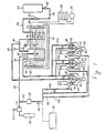
- Figure 1 is a schematic diagram of the mechanical refrigeration system of the portable post-mix beverage dispenser unit in accordance with one embodiment of this invention;
- Figure 2 is a front elevation view of a portable post-mix beverage dispenser unit as shown in Figure 1;
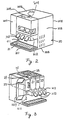
- Figure 3 is a front perspective view of a portable post-mix beverage dispenser unit as shown in Figure 1 with access panel and the top access panel removed to illustrate a compartment for the portable tank and the syrup supply compartment;
- Figure 4 is a cross-sectional view showing the connection between a syrup package and a receiving portion;
- Figure 5 is a schematic diagram of showing a part of the portable post-mix beverage dispenser unit as shown in Figure 1; and
- Figure 6 is an electrical circuit for driving an electromagnetic valve.
- Figures 1-3 show a portable post-mix beverage dispenser unit in accordance with one embodiment of this invention. The unit includes a cabinet 20 having a
front access panel 201,top access panel 202, rightside access panel 203, leftside access panel 204, rearside access panel 205, bottom access panel 206 andadditional access panel 207.Front access panel 201 carries a permanent magnet 201a attached thereon adjacent thetop access panel 202. Thetop access panel 202 includes reed switch 202a attached thereon adjacent the permanent magnet 201a onfront access panel 201 so that reed switch 202a is turned on whenfront access panel 201 is located on cabinet 20. Permanent magnet 201a and reed switch 202a form a detecting device 60 to detect whetherfront access panel 201 is located on cabinet 20 or not. Pouring station 21 is located belowfront access panel 201 and includes adrain plate 211 for receiving cups and for draining liquid spilled from the cups through a plurality of slits. Dispensingportion 212 is located betweenpanel 201 and pouring station 21 and includesvalve levers 213 extending downwardly in front. A cooling reservoir 22 is disposed in one upper corner of cabinet 20 and is covered by an insulating material. A carbonator 23, part of acooling pipe 24, an agitator 25, and anice sensor 26 are all disposed within cooling reservoir 22. Reservoir 22 stores cool water which is used for cooling potable water introduced to carbonator 23 throughcooling pipe 24. - A
portable tank 27 is removably disposed in an upper left side of cabinet 20 and is used to store and supply potable water, both to be carbonated and to be mixed directly with the syrup.Control box 28, CO₂ cylinder ortank 29, and a plurality of syrup packages S1, S2 and S3 located above and connected to dispensingportion 212, are disposed in an upper part of cabinet 20.Pump 30,compressor 31 andcondenser 54 are disposed in a lower part of cabinet 20.Portable tank 27 is linked topump 30 through sealing coupler 32 and first conduit 33. Sealing coupler 32 connects one end of first conduit 33 toportable tank 27 such that first conduit 33 can be disconnected therefrom without leakage of water. First conduit 33 is further linked withpump 30, and on the other side ofpump 30 is linked tocooling pipe 24.Cooling pipe 24 has arectangular serpentine portion 241 disposed in cooling reservoir 22. The other end ofcooling pipe 24 is linked tosecond conduit 34 and tothird conduit 35 through three-wayelectromagnetic valve 36.Second conduit 34 has acheck valve 37 and extends to the interior of carbonator 23 located in cooling reservoir 22.Third conduit 35 is divided into three sub-conduits 35a, 35b and 35c, each sub-conduit coupled with a respective valve V1, V2 or V3 through respectiveflow control valves 38 disposed in dispensingportion 212. -
CO₂ cylinder 29 is linked to the interior of carbonator 23 throughfourth conduit 39.Check valve 40 and reducingvalve 41 includingpressure gauge 411 are disposed infourth conduit 39 betweencylinder tank 29 and carbonator 23. Carbonated water is produced in carbonator 23 by mixing cooled water fromportable tank 27 with CO₂ fromCO₂ cylinder 29. - A
fifth conduit 42 is linked tofourth conduit 39 at a location between reducingvalve 41 andcheck valve 40.Fifth conduit 42 includes a reducingvalve 43 and anelectromagnetic valve 44. After the location ofelectromagnetic valve 44,fifth conduit 42 splits into threesubconduits respective check valve 45.Subconduits flow control valves 46. Reducingvalve 43 reduces the pressure of CO₂ withinfifth conduit 42 to a level of about 0.4 Kg/Cm2. - The carbonator 23 contains cooled carbonated water. A sixth conduit 47 extends from near the bottom of carbonator 23, and is divided into three
subconduits 47a, 47b and 47c at the other end.Subconduits 47a, 47b and 47c are coupled with valves V1, V2 and V3 respectively, through respectiveflow control valves 48. Valves V1, V2 and V3 are connected at their other ends tonozzles respective cups 52. - Evaporator 53 is disposed along the outer surface of the inner wall of cooling reservoir 22, and cools the water in cooling reservoir 22. Evaporator 53 forms part of a refrigeration circuit also including at least
compressor 31 andcondenser 54 located externally of cooling reservoir 22 within cabinet 20. The water in reservoir 22 is cooled by evaporator 53 until it is at a temperature of about 0oC. -
Electromagnetic valve 44 is connected to control device 60, and opens and closes communication offifth conduit 42 between reducingvalve 43 andcheck valve 45 in accordance with instruction from detecting device 60. - In operation, a user places a cup on
drain plate 211 below a selected one ofnozzle valve levers 213 which corresponds to the selected nozzle, simultaneously operatingpump 30 and three wayelectromagnetic valve 36.Pump 30 pumps water fromportable tank 27 through first conduit 33 and intoserpentine portion 241 ofcooling pipe 24, where it is cooled by the cooling water in reservoir 22. Thereafter, the water flows through three-wayelectromagnetic valve 36 into carbonator 23 where it is mixed with CO₂ fromCO₂ cylinder 29 to carbonate the water.Float switch 55 controls the volume of carbonated water in carbonator 23. If the level of carbonated water is below a predetermined level, pump 30 operated and more potable water is supplied to carbonator 23 along with CO₂ to raise the level of carbonated water back to the predetermined level. The water supplied to carbonator 23 is in the form of mist. - Carbonated water mixed in carbonator 23 flows through sixth conduit 47, and through the appropriate subconduit to respective
flow control valve 48. Additionally, potable water is sent directly to oneflow control valve 38 in dispensingportion 212 throughthird conduit 35 and the appropriate subconduit fromelectromagnetic valve 36. That is, water flows fromserpentine portion 241 without passing through carbonator 23. Finally, syrup flows from one of the appropriate syrup packages S1, S2 and S3 to respectiveflow control valves 46 due to the pressure of the CO₂ inconduit 45 and the appropriate subconduit. Since the CO₂ inconduit 45, and e.g.,subconduit 42a is supplied to the interior of syrup package S1 as shown in Figures 4 and 5 and the pressure of the CO₂ is constant, the flow rate of syrup from syrup package S1 to flowcontrol valve 46 also becomes constant. The volume of carbonated water, potable water and syrup are controlled atflow control valves nozzle cup 52. - Since
CO₂ cylinder 29 and syrup packages S1, S2 and S3 are detachable, when the contents of the tank or a syrup package is exhausted, the tank or package is removed and replaced with a fresh supply. For this,front access panel 201 is removed from cabinet 20. The permanent magnet 201a is therefore separated from the reed switch 202a attached ontop access panel 202. Therefore, reed switch 202a is turned off, thereby to stop supplying solenoid 44a ofelectromagnetic valve 44 with electric current frompower source 61, as shown in Figure 6.Electromagnetic valve 44 thus closes the communication betwenfifth conduit 42 andrespective subconduits electromagnetic valve 44. Therefore, even though one or more syrup packages S1, S2 and S3 are removed from correspondingsubconduits CO₂ cylinder 29 is prevented from venting to the atmosphere. - After replacement with a fresh supply, when
front access panel 201 is disposed on dispensingportion 212, permanent magnet 201a is adjacent to reed switch 202a. Solenoid 44a ofelectromagnetic valve 44 is thus connected topower source 61. Accordingly,electromagnetic valve 44 opens the communication betweenfifth conduit 42 andrespective subconduits - This invention has been described in connection with a preferred embodiment. The preferred embodiment, however, is merely for example only and the invention is not restricted thereto. It can be easily understood by those skilled in the art that variations and modifications can be easily made within the scope of this invention as defined by the appended claims.
Claims (12)
Applications Claiming Priority (2)
| Application Number | Priority Date | Filing Date | Title |
|---|---|---|---|
| JP1988131731U JPH0252800U (en) | 1988-10-11 | 1988-10-11 | |
| JP131731/88U | 1988-10-11 |
Publications (2)
| Publication Number | Publication Date |
|---|---|
| EP0364206A1 true EP0364206A1 (en) | 1990-04-18 |
| EP0364206B1 EP0364206B1 (en) | 1993-03-31 |
Family
ID=15064879
Family Applications (1)
| Application Number | Title | Priority Date | Filing Date |
|---|---|---|---|
| EP89310336A Expired - Lifetime EP0364206B1 (en) | 1988-10-11 | 1989-10-10 | Post-mix beverage dispenser unit |
Country Status (5)
| Country | Link |
|---|---|
| US (1) | US5086951A (en) |
| EP (1) | EP0364206B1 (en) |
| JP (1) | JPH0252800U (en) |
| KR (1) | KR970007236B1 (en) |
| DE (1) | DE68905746T2 (en) |
Cited By (9)
| Publication number | Priority date | Publication date | Assignee | Title |
|---|---|---|---|---|
| DE19526215A1 (en) * | 1994-08-22 | 1996-02-29 | Unifontes Ag | Cold drinks dispensing machine |
| US5647512A (en) * | 1994-03-04 | 1997-07-15 | Spal Industria Brasileira De Bebidas S/A | Soda dispensing machine |
| EP1764148A1 (en) * | 2005-09-14 | 2007-03-21 | Jäger, Urs | Device for making mixed beverages, and pressurized container therefore |
| WO2014144873A1 (en) * | 2013-03-15 | 2014-09-18 | The Coca-Cola Comapny | Efficiently and easily opening and closing a canister valve |
| US9216887B2 (en) | 2013-03-15 | 2015-12-22 | The Coca-Cola Company | Efficiently and easily opening and closing a canister valve |
| EP3000780A1 (en) * | 2014-09-26 | 2016-03-30 | Anheuser-Busch InBev S.A. | Beverage dispensing assembly comprising an ingedient container receiving means and a gas pressure regulator |
| EP3643989A1 (en) * | 2014-10-20 | 2020-04-29 | Bedford Systems LLC | Beverage machine with thermoelectric cooler, heat pipe and heat sink arrangement |
| CN114599601A (en) * | 2019-11-01 | 2022-06-07 | 朝日集团控股株式会社 | Dispensing head and beverage dispenser |
| CN114599601B (en) * | 2019-11-01 | 2024-05-03 | 朝日集团控股株式会社 | Injection head and beverage supplier |
Families Citing this family (15)
| Publication number | Priority date | Publication date | Assignee | Title |
|---|---|---|---|---|
| US5249710A (en) * | 1992-07-02 | 1993-10-05 | Imi Cornelius Inc. | Beverage dispenser having cold plate with evaporative cooling |
| DE4228775A1 (en) * | 1992-08-28 | 1994-03-03 | Bosch Siemens Hausgeraete | Device for preparing and dispensing soft drinks |
| US5341957A (en) * | 1993-01-08 | 1994-08-30 | Sizemore Sean S | Cup-type vending system and method for dispensing beverages |
| US5651482A (en) * | 1993-01-08 | 1997-07-29 | Sizemore; Sean S. | Syrup delivery kit for vending system |
| US5333759A (en) * | 1993-01-14 | 1994-08-02 | Lancer Corporation | Modular dispensing tower |
| US5531254A (en) * | 1994-02-22 | 1996-07-02 | Rosenbach; Arnie | Portable hand activated carbonator |
| US5556006A (en) * | 1994-04-05 | 1996-09-17 | Fuji Electric Co., Ltd. | Drink supply apparatus |
| US5765726A (en) * | 1995-09-27 | 1998-06-16 | Imi Wilshire Inc. | Combined carbonated and non-carbonated beverage dispenser |
| AU7032801A (en) * | 2000-10-09 | 2002-04-11 | Samsung Gwangju Electronics Co., Ltd. | Ice cream vending machine |
| US20110182652A1 (en) * | 2010-01-22 | 2011-07-28 | Hannah Chung | Wearable Sanitizing Gel Dispenser, Kit, and Associated Methods |
| US20110181417A1 (en) * | 2010-01-25 | 2011-07-28 | Lancer Partnership, Ltd | Method and apparatus for beverage dispensing |
| US20140263406A1 (en) * | 2013-03-14 | 2014-09-18 | The Coca-Cola Company | Beverage Dispenser with Integrated Carbonator and a Potable Water/Ice Slurry Refrigeration System |
| US20160229677A1 (en) * | 2013-09-24 | 2016-08-11 | Nestec S.A. | Solenoid valve for a beverage dispensing device |
| EP3000779A1 (en) * | 2014-09-26 | 2016-03-30 | Anheuser-Busch InBev S.A. | Beverage dispensing device comprising at least two pod or capsule receiving means |
| US10743563B2 (en) * | 2015-10-02 | 2020-08-18 | The Vollrath Company, L.L.C. | Frozen beverage dispenser |
Citations (6)
| Publication number | Priority date | Publication date | Assignee | Title |
|---|---|---|---|---|
| US3638392A (en) * | 1970-02-20 | 1972-02-01 | Harry Logue Welker Jr | Automatics slush dispensing machine |
| GB1414982A (en) * | 1972-01-25 | 1975-11-26 | Granley Products London Ltd | Device responsive to the opening of a door |
| EP0102527A2 (en) * | 1982-08-02 | 1984-03-14 | The Coca-Cola Company | Beverage dispenser |
| GB2152011A (en) * | 1983-11-16 | 1985-07-31 | Coca Cola Co | Post-mix beverage dispenser with cooled water and syrup |
| EP0181450A1 (en) * | 1984-11-16 | 1986-05-21 | The Coca-Cola Company | Beverage quality security apparatus for post-mix beverage dispenser |
| EP0320262A1 (en) * | 1987-12-08 | 1989-06-14 | Sanden Corporation | Portable post-mix dispenser unit |
Family Cites Families (9)
| Publication number | Priority date | Publication date | Assignee | Title |
|---|---|---|---|---|
| US2894377A (en) * | 1956-12-03 | 1959-07-14 | Jr Horace E Shiklers | Beverage dispensing apparatus |
| US3240395A (en) * | 1963-01-22 | 1966-03-15 | Fred M Carver | Self-contained portable dispensing system |
| US4148334A (en) * | 1975-09-05 | 1979-04-10 | Fluid Device Corporation | Liquid level control sytem |
| US4304736A (en) * | 1980-01-29 | 1981-12-08 | The Coca-Cola Company | Method of and apparatus for making and dispensing a carbonated beverage utilizing propellant carbon dioxide gas for carbonating |
| US4440318A (en) * | 1980-03-11 | 1984-04-03 | Irving Berger | Beverage dispenser |
| US4688701A (en) * | 1981-06-26 | 1987-08-25 | The Coca-Cola Company | Self-contained portable post-mix beverage dispenser apparatus having access for manually loading syrup CO2 and water |
| US4493441A (en) * | 1981-11-12 | 1985-01-15 | The Coca-Cola Company | Portable post-mix beverage dispenser unit |
| US4921139A (en) * | 1984-10-22 | 1990-05-01 | The Coca-Cola Company | Refrigeration system for a beverage dispenser |
| JPS6146686U (en) * | 1984-08-31 | 1986-03-28 | サンデン株式会社 | beverage vending machine |
-
1988
- 1988-10-11 JP JP1988131731U patent/JPH0252800U/ja active Pending
-
1989
- 1989-10-10 EP EP89310336A patent/EP0364206B1/en not_active Expired - Lifetime
- 1989-10-10 DE DE89310336T patent/DE68905746T2/en not_active Expired - Fee Related
- 1989-10-11 US US07/421,587 patent/US5086951A/en not_active Expired - Fee Related
- 1989-10-11 KR KR1019890014557A patent/KR970007236B1/en not_active IP Right Cessation
Patent Citations (6)
| Publication number | Priority date | Publication date | Assignee | Title |
|---|---|---|---|---|
| US3638392A (en) * | 1970-02-20 | 1972-02-01 | Harry Logue Welker Jr | Automatics slush dispensing machine |
| GB1414982A (en) * | 1972-01-25 | 1975-11-26 | Granley Products London Ltd | Device responsive to the opening of a door |
| EP0102527A2 (en) * | 1982-08-02 | 1984-03-14 | The Coca-Cola Company | Beverage dispenser |
| GB2152011A (en) * | 1983-11-16 | 1985-07-31 | Coca Cola Co | Post-mix beverage dispenser with cooled water and syrup |
| EP0181450A1 (en) * | 1984-11-16 | 1986-05-21 | The Coca-Cola Company | Beverage quality security apparatus for post-mix beverage dispenser |
| EP0320262A1 (en) * | 1987-12-08 | 1989-06-14 | Sanden Corporation | Portable post-mix dispenser unit |
Cited By (15)
| Publication number | Priority date | Publication date | Assignee | Title |
|---|---|---|---|---|
| US5647512A (en) * | 1994-03-04 | 1997-07-15 | Spal Industria Brasileira De Bebidas S/A | Soda dispensing machine |
| DE19526215A1 (en) * | 1994-08-22 | 1996-02-29 | Unifontes Ag | Cold drinks dispensing machine |
| EP1764148A1 (en) * | 2005-09-14 | 2007-03-21 | Jäger, Urs | Device for making mixed beverages, and pressurized container therefore |
| WO2007030966A2 (en) * | 2005-09-14 | 2007-03-22 | Urs Jaeger | Device for production of mixed drinks and pressurised container for the same |
| WO2007030966A3 (en) * | 2005-09-14 | 2007-05-18 | Urs Jaeger | Device for production of mixed drinks and pressurised container for the same |
| US9216887B2 (en) | 2013-03-15 | 2015-12-22 | The Coca-Cola Company | Efficiently and easily opening and closing a canister valve |
| WO2014144873A1 (en) * | 2013-03-15 | 2014-09-18 | The Coca-Cola Comapny | Efficiently and easily opening and closing a canister valve |
| US9518691B2 (en) | 2013-03-15 | 2016-12-13 | The Coca-Cola Company | Efficiently and easily opening and closing a canister valve |
| US9651188B2 (en) | 2013-03-15 | 2017-05-16 | The Coca-Cola Company | Efficiently and easily opening and closing a canister valve |
| EP3000780A1 (en) * | 2014-09-26 | 2016-03-30 | Anheuser-Busch InBev S.A. | Beverage dispensing assembly comprising an ingedient container receiving means and a gas pressure regulator |
| WO2016046378A1 (en) * | 2014-09-26 | 2016-03-31 | Anheuser-Busch Inbev S.A. | Beverage dispensing assembly comprising an ingredient container receiving means and a gas pressure regulator and method of dispensing a beverage with such assembly |
| CN107074518A (en) * | 2014-09-26 | 2017-08-18 | 安海斯-布希英博股份有限公司 | The method received the beverage distribution component of the gentle body pressure regulator of device including component container and beverage is distributed using this component |
| EP3643989A1 (en) * | 2014-10-20 | 2020-04-29 | Bedford Systems LLC | Beverage machine with thermoelectric cooler, heat pipe and heat sink arrangement |
| CN114599601A (en) * | 2019-11-01 | 2022-06-07 | 朝日集团控股株式会社 | Dispensing head and beverage dispenser |
| CN114599601B (en) * | 2019-11-01 | 2024-05-03 | 朝日集团控股株式会社 | Injection head and beverage supplier |
Also Published As
| Publication number | Publication date |
|---|---|
| KR900006225A (en) | 1990-05-07 |
| US5086951A (en) | 1992-02-11 |
| JPH0252800U (en) | 1990-04-16 |
| DE68905746D1 (en) | 1993-05-06 |
| DE68905746T2 (en) | 1993-09-30 |
| KR970007236B1 (en) | 1997-05-07 |
| EP0364206B1 (en) | 1993-03-31 |
Similar Documents
| Publication | Publication Date | Title |
|---|---|---|
| EP0364206B1 (en) | Post-mix beverage dispenser unit | |
| US4960228A (en) | Portable post-mix beverage dispenser unit | |
| EP0299767B1 (en) | Premix dispensing system | |
| US4493441A (en) | Portable post-mix beverage dispenser unit | |
| CA1145303A (en) | Post-mix beverage dispensing system syrup package, valving system and carbonator therefor | |
| EP2576422B1 (en) | System and method for rapid reconfiguration of post-mix beverage dispenser | |
| US4687120A (en) | Method and apparatus for dispensing cold beverage | |
| US5139708A (en) | Dual chamber carbonator for dispensing drinks | |
| US5842603A (en) | Postmix juice dispenser | |
| JP2000512959A (en) | Post-mix beverage dispenser | |
| US3206069A (en) | Apparatus and method for carbonating and dispensing beverages | |
| AU5832490A (en) | Apparatus for making or dispensing drinks | |
| CA2324200A1 (en) | Juice dispenser with removable cooled cabinet | |
| US5556006A (en) | Drink supply apparatus | |
| US6732885B2 (en) | Beverage supply system | |
| EP0080253B1 (en) | Post-mix beverage dispenser | |
| EP0319348A2 (en) | Convertible beverage dispenser | |
| EP0947518A1 (en) | Automatic drinks vending machine | |
| GB2133086A (en) | Method and apparatus for dispensing cold beverage | |
| JPH08156997A (en) | Drink dispenser | |
| WO2004020325A2 (en) | Beverage supply system | |
| GB2160503A (en) | Beverage dispensing apparatus; ice dispensing | |
| JP3684310B2 (en) | Beverage dispenser equipment | |
| JP3432021B2 (en) | Beverage dispenser | |
| JP2000109191A (en) | Drink liquid supply device |
Legal Events
| Date | Code | Title | Description |
|---|---|---|---|
| PUAI | Public reference made under article 153(3) epc to a published international application that has entered the european phase |
Free format text: ORIGINAL CODE: 0009012 |
|
| AK | Designated contracting states |
Kind code of ref document: A1 Designated state(s): DE GB IT |
|
| 17P | Request for examination filed |
Effective date: 19900623 |
|
| 17Q | First examination report despatched |
Effective date: 19920518 |
|
| GRAA | (expected) grant |
Free format text: ORIGINAL CODE: 0009210 |
|
| AK | Designated contracting states |
Kind code of ref document: B1 Designated state(s): DE GB IT |
|
| REF | Corresponds to: |
Ref document number: 68905746 Country of ref document: DE Date of ref document: 19930506 |
|
| ITF | It: translation for a ep patent filed |
Owner name: MODIANO & ASSOCIATI S.R.L. |
|
| PLBE | No opposition filed within time limit |
Free format text: ORIGINAL CODE: 0009261 |
|
| STAA | Information on the status of an ep patent application or granted ep patent |
Free format text: STATUS: NO OPPOSITION FILED WITHIN TIME LIMIT |
|
| 26N | No opposition filed | ||
| PGFP | Annual fee paid to national office [announced via postgrant information from national office to epo] |
Ref country code: GB Payment date: 19951002 Year of fee payment: 7 |
|
| PGFP | Annual fee paid to national office [announced via postgrant information from national office to epo] |
Ref country code: DE Payment date: 19951012 Year of fee payment: 7 |
|
| PG25 | Lapsed in a contracting state [announced via postgrant information from national office to epo] |
Ref country code: GB Effective date: 19961010 |
|
| GBPC | Gb: european patent ceased through non-payment of renewal fee |
Effective date: 19961010 |
|
| PG25 | Lapsed in a contracting state [announced via postgrant information from national office to epo] |
Ref country code: DE Effective date: 19970701 |
|
| PG25 | Lapsed in a contracting state [announced via postgrant information from national office to epo] |
Ref country code: IT Free format text: LAPSE BECAUSE OF NON-PAYMENT OF DUE FEES Effective date: 20051010 |