EP0363290A1 - Crank for a fishing reel - Google Patents
Crank for a fishing reel Download PDFInfo
- Publication number
- EP0363290A1 EP0363290A1 EP19890420376 EP89420376A EP0363290A1 EP 0363290 A1 EP0363290 A1 EP 0363290A1 EP 19890420376 EP19890420376 EP 19890420376 EP 89420376 A EP89420376 A EP 89420376A EP 0363290 A1 EP0363290 A1 EP 0363290A1
- Authority
- EP
- European Patent Office
- Prior art keywords
- handle
- arm
- axial portion
- shoulder
- crank
- Prior art date
- Legal status (The legal status is an assumption and is not a legal conclusion. Google has not performed a legal analysis and makes no representation as to the accuracy of the status listed.)
- Granted
Links
- 230000002093 peripheral effect Effects 0.000 claims description 10
- 230000035939 shock Effects 0.000 claims description 8
- 230000000694 effects Effects 0.000 claims description 5
- 238000006073 displacement reaction Methods 0.000 claims description 4
- 229920001971 elastomer Polymers 0.000 claims description 4
- 239000000806 elastomer Substances 0.000 claims description 4
- 230000035515 penetration Effects 0.000 claims description 4
- 238000010521 absorption reaction Methods 0.000 claims description 3
- 230000000717 retained effect Effects 0.000 claims description 3
- 230000001464 adherent effect Effects 0.000 claims description 2
- 238000004804 winding Methods 0.000 claims description 2
- 210000000056 organ Anatomy 0.000 claims 1
- 230000000149 penetrating effect Effects 0.000 abstract description 2
- 210000002105 tongue Anatomy 0.000 description 5
- 239000000463 material Substances 0.000 description 3
- 230000006866 deterioration Effects 0.000 description 2
- 238000011084 recovery Methods 0.000 description 2
- 238000005096 rolling process Methods 0.000 description 2
- 239000004677 Nylon Substances 0.000 description 1
- 230000007547 defect Effects 0.000 description 1
- 239000013013 elastic material Substances 0.000 description 1
- 238000004519 manufacturing process Methods 0.000 description 1
- 229920001778 nylon Polymers 0.000 description 1
- 239000011241 protective layer Substances 0.000 description 1
- 238000007789 sealing Methods 0.000 description 1
Images

Classifications
-
- A—HUMAN NECESSITIES
- A01—AGRICULTURE; FORESTRY; ANIMAL HUSBANDRY; HUNTING; TRAPPING; FISHING
- A01K—ANIMAL HUSBANDRY; AVICULTURE; APICULTURE; PISCICULTURE; FISHING; REARING OR BREEDING ANIMALS, NOT OTHERWISE PROVIDED FOR; NEW BREEDS OF ANIMALS
- A01K89/00—Reels
- A01K89/006—Hand crank features
-
- G—PHYSICS
- G05—CONTROLLING; REGULATING
- G05G—CONTROL DEVICES OR SYSTEMS INSOFAR AS CHARACTERISED BY MECHANICAL FEATURES ONLY
- G05G1/00—Controlling members, e.g. knobs or handles; Assemblies or arrangements thereof; Indicating position of controlling members
- G05G1/08—Controlling members for hand actuation by rotary movement, e.g. hand wheels
- G05G1/085—Crank handles
-
- Y—GENERAL TAGGING OF NEW TECHNOLOGICAL DEVELOPMENTS; GENERAL TAGGING OF CROSS-SECTIONAL TECHNOLOGIES SPANNING OVER SEVERAL SECTIONS OF THE IPC; TECHNICAL SUBJECTS COVERED BY FORMER USPC CROSS-REFERENCE ART COLLECTIONS [XRACs] AND DIGESTS
- Y10—TECHNICAL SUBJECTS COVERED BY FORMER USPC
- Y10T—TECHNICAL SUBJECTS COVERED BY FORMER US CLASSIFICATION
- Y10T74/00—Machine element or mechanism
- Y10T74/20—Control lever and linkage systems
- Y10T74/20576—Elements
- Y10T74/20732—Handles
- Y10T74/20744—Hand crank
Definitions
- the present invention relates to fishing reels comprising a fishing line recovery mechanism.
- the nylon fishing line is wound on an axial reel, i.e. a reel whose axis is substantially parallel to the longitudinal axis of the fishing rod .
- the wire is gradually wound on the spool by a recuperator animated by a rotation movement of longitudinal axis around the spool and driven by a crank whose end forms a handle.
- the crank has a radial arm, a first end of which carries the main rotation shaft for crank connection on the reel body, and a second end of which carries a handle rotatably mounted on the arm.
- the main crank rotation shaft is substantially perpendicular to the main longitudinal axis of the reel, or longitudinal axis of the fishing rod.
- the handle is rotatable around a screw forming an axial rotation shaft parallel to the main crank rotation shaft. As a result, the handle occupies a highly prominent position on the side of the fishing rod and reel, which makes it easily accessible and easy to handle.
- the handle is formed by a rigid body, of generally flattened parallelepiped shape, provided with a through bore in which is inserted with little play a screw the head of which bears on the external face of the handle body and the end of the rod of which is screwed to the end of the radial crank arm.
- the handle has a bearing face cooperating by sliding with little play with the end of the crank arm.
- the fishing reel crank By its strongly prominent position, the fishing reel crank, and in particular its handle, are liable to undergo relatively violent shocks when using the fishing gear. These violent and repeated shocks most often lead to twisting or a break in the screw connecting the handle to the crank arm. Shocks also lead to deterioration of the external handle surface, which surface must be in an appropriate state to avoid slipping of the user's fingers. This results in unacceptable deterioration of the handles and the crank arms.
- annular groove existing between the crank and the handle leads to specific problems appearing due to the use of reels with a fishing line, a wire generally of small section: during certain phases of use of the material, the fishing line coming out of the spool tends to wind in the groove between the handle and the crank arm, and to get caught in this groove. This risk of jamming and rolling up constitutes a serious and unacceptable drawback.
- the object of the present invention is in particular to avoid the drawbacks mentioned above, by providing means making it possible to absorb the shocks suffered by the handles and the crank arm in a fishing reel.
- Such shock absorption limits the stresses undergone by the connecting screw between the crank handle and the arm, and the stresses undergone by the crank arm itself and by the handle itself.
- Another advantage of the present invention lies in the fact that the handle itself is protected by an interchangeable member forming its surface surface, so that any damage to the crank grip surface can be canceled by changing the surface element , without having to change the entire crank.
- the reel according to the invention is provided with a particular connection between the handle and the crank arm, this connection making it possible to eliminate the presence of the annular groove in which the wire is wound. fishing in known reels.
- the fishing reel comprises a crank comprising in known manner a handle and a crank arm, the arm comprising an axial portion forming a handle rotation shaft passing through a handle bore :
- the handle comprises a rigid body pierced with the through bore which opens onto the end face handle moth; the rigid body is covered with an elastomer hood simultaneously covering the peripheral faces and the end face of the rigid body.
- the handle has mechanical shock absorption properties, it has a deformable and gripping gripping surface, and the hood also prevents the penetration of foreign bodies into the handle through bore.
- the peripheral surface of the rigid handle body has asperities cooperating with the internal surface of the hood to prevent untimely tearing of said hood.
- the hood is fitted under tension on the rigid body and is retained on the body by the effect of its elasticity, so that it is easily interchangeable.
- the second end of the crank arm comprises an external axial portion extended by the handle, and of SE cross section less than the handle section SP, the arm comprising a shoulder limiting the relative axial displacement of the handle towards the arm;
- the external axial portion of the arm is extended by an axial portion of the arm internal to the handle, of section SI being connected by its first end at the end of the external axial portion, said shoulder limiting the relative axial displacement of the handle in direction of the arm is formed by the second end of the internal axial portion;
- the internal axial portion is housed in a handle end bore;
- the section SE of external axial portion is less than or equal to the section SI of internal axial portion.
- FIGs 1 and 2 are intended to better understand the problems mentioned above, which appear in known fishing reels.
- FIGS. 1 - I illustrate a form of known fishing reel crank, comprising a radial arm 1 of which a first end 2 carries the main rotation shaft 3 of crank, and whose second end 4 carries a handle 5 rotatably mounted on the arm according to a handle axial rotation shaft.
- the main rotation shaft 3 of the crank develops in a direction I - I generally perpendicular to the longitudinal direction of reel of reel and fishing rod, and is connected to the usual bodies for winding the fishing line on the reel of reel .
- the main rotation shaft 3 of the crank therefore pivots in the reel body, not shown in the figures, in a manner known per se.
- the handle 5 is rotatable about an axis II - II generally parallel to the direction I - I of the main crank rotation shaft, or axial direction.
- the handle 5 is generally connected to the radial arm 1 by a shouldered screw 6: the handle 5 consists of a rigid body 7 pierced right through by an axial bore 8; the shouldered screw 6 passes through the bore 8 with little play, and its head 9 bears against a first end facet 10 of the rigid crank body 7; the end 11 of the screw rod 6 is screwed into a corresponding threaded bore of the second end 4 of radial arm 1; the intermediate shoulder 12 of the screw 6 bears against a facet 13 of the radial arm 1. Sufficient clearance is provided to allow a slight axial translation of the handle body 7 on the shouldered screw rod 6, between the head 9 and the facet of radial arm 13.
- FIGS. 1 and 2 show the appearance of an annular peripheral groove 14 between the rigid handle body and the second end 4 of radial arm 1.
- the fishing line in certain phases use of the material, risk of rolling up and getting stuck in the throat 14.
- the reel according to the invention also includes the main elements of the known reel cranks shown in FIGS. 1 and 2, main elements which have been used with the same reference numbers, and in particular: radial arm 1, main crank rotation shaft 3, handle 5, rigid body 7, connecting screw 6.
- the rigid body 7 of the handle is internal, and is covered with an elastomer hood 15 simultaneously covering the peripheral faces 16 and the end face 17 of the rigid body 7.
- the hood 15 of elastic material forms a protective layer which absorbs shock.
- hood 15 which covers the peripheral face 16 of the rigid body 7, by itself forms the gripping surface of the crank.
- said gripping surface is deformable and adherent, which facilitates its handling and makes it particularly pleasant.
- the hood 15 also opposes the penetration of foreign bodies into the handle bore 8, because it forms a continuous and sealed wall covering the end zone occupied by the screw head 9.
- the peripheral surface 16 of the rigid body 7 of the handle advantageously has roughness such as the end protrusion 18 and the opposite protrusion 19, cooperating with the internal surface of the hood 15 to prevent untimely tearing of said hood.
- the hood is fitted under tension on the rigid body 7, and is retained on the body by the effect of its elasticity.
- the hood 15 is thus easily interchangeable. It has, on its peripheral external face, asperities schematically represented by axial lines 20 in FIG. 4, which increase the adhesion between the handle and the user's fingers. At the end of a fishing season, if said roughness 20 is worn, it is possible to easily remedy this defect by changing the hood 15.
- the connection between the handle 5 and the radial arm 1 takes place according to a new and advantageous structure.
- the second end 4 of the radial arm 1 has an external axial portion 21, extending parallel to the crank axis II - II, which external axial portion 21 is extended by the handle.
- the external axial portion 21 has a cross section SE less than the handle section SP.
- the external axial portion 21 of the arm is extended by an internal axial portion of the arm 22, of section SI, and which is connected by its first end to the end of the external axial portion 21.
- the second end 23 of the internal axial portion 22 forms a limiting shoulder the axial displacement of the handle 5 in the direction of the radial arm 1.
- the internal axial portion 22 is housed in a bore 24 at the end of the handle.
- the section SE of external axial portion 21 is less than or equal to the section SI of internal axial portion 22 of the arm.
- the shoulder formed by the second end 23 of internal axial portion which limits the axial movement of the handle in the direction of the radial arm, occupies an intermediate position inside the handle, that is to say a position not visible and not accessible by the fishing line. As a result, the fishing line does not risk being wound up and getting caught between said shoulder 23 and the handle.
- connection between the handle 5 and the radial arm 1 is also ensured by an axial screw 6, the head 9 of which limits the axial movement of the handle away from the arm 1, and the end 11 is screwed into a threaded bore of the second end 4 of the radial arm.
- the screw 6 does not have an intermediate shoulder, but cooperates with a shouldered sleeve 25.
- the sleeve 25 comprises a tubular body, crossed by the screw rod 6, the first end of which bears on the screw head 9, the second end of which comprises a sleeve shoulder 26 forming a bearing surface against the second end 23 of the axial portion 22 of the radial arm 1.
- the sleeve 25 limits the screwing of the screw 6 into the bore threaded radial arm.
- the sleeve 25 bears on the one hand on the head 9 of the screw and on the other hand on the shoulder 23 of the end of the radial arm 1. In this embodiment, a small clearance is left to allow a slight axial movement of the rigid body 7 of the handle on the sleeve 25, between the head 9 of the screw and the shoulder 26 of the sleeve.
- the internal axial portion 22 of the radial arm, or portion penetrating into the handle bore 24, must have a length equal to several times the diameter of the fishing line.
- the external axial portion 21 of the radial arm must have a length equal to several times the diameter of the fishing line. This prevents jamming of the fishing line between the handle and the radial arm.
- connection structure between the handle 5 and the radial arm 1 as shown in FIG. 3 leads to a substantial increase in the length of the portion of the radial arm 1 into which the screw 6 penetrates.
- This part is in fact made up of: firstly by the external axial portion 21 of the radial arm, and also by the internal axial portion 22 of the radial arm. This results in a significant increase in the mechanical strength of this connection.
- connection between the handle 5 and the radial arm 1 has the same elements as in the embodiment of Figure 3, but further comprises elastic means interposed between the portion axial of the arm and the handle, to push the handle in abutment against the base of the screw head 9, opposite the radial arm.
- the elastic means comprise an elastomeric O-ring 30, housed between the second end 23 of the internal axial portion 22 of the arm forming the shoulder, and between the rigid body 7 of the handle.
- the tightening of the screw 6 causes a slight crushing of the O-ring 30, which thus acts as an elastic member pushing the handle 5 against the screw head 9.
- the O-ring 30 simultaneously acts as a seal d sealing, limiting the penetration of foreign bodies into the handle, inside the bore 8.
- the O-ring 30 is disposed at the periphery of the shoulder 26 of the sleeve 25, so that said shoulder 26 ensures the centering of the O-ring 30 and limits its crushing.
- the elastic means comprise one or more axial tongues, for example four tongues 31, 32, 33 and 34, protruding from the internal face of the end wall 35 of the hood 15, and shaped to rest elastically on the screw head 9.
- the elastic tabs 31 - 34 ensure a backlash in a preferential direction, avoiding the bell effect.
- the additional deformation generated absorbs energy.
- the handle rotation shaft consists of a hollow shaft 40, embedded at its first end 41 in the crank arm 1, and having at its second end a blind hole 42 tapped in which is screwed a screw 6 with a smooth domed head 9.
- the connecting surfaces between the axial portion 21 of the radial arm and the handle body are similar to those of the previous embodiments, that is to say that they comprise an external axial portion 21, an internal axial portion 22, a second end 23 of internal axial portion forming a shoulder limiting the axial movement of the handle 5 in the direction of the radial arm 1.
- the base 43 of the screw head 9 limits the axial movement of the handle 5 away from the arm 1.
- the axial clearance of the handle 5 between the base 43 of the screw head 9 and the shoulder 23 is adjusted by means of a washer 44 of appropriate thickness inserted between the base 43 of the screw head 9 and the face corresponding front 45 of the rigid body 7 of the handle.
- An elastic tongue 31, possibly associated with other similar elastic tongues, protrudes from the internal face of the end wall 35 of the hood 15 covering the peripheral faces and the end face of the rigid body 7.
- the elastic tongue 31 comes wear on the domed end face of the head 9 smooth with a screw, to push the handle 5 away from the arm 1. This variant also ensures backlash in the preferential direction, avoiding the effect of the bell, and allows precise adjustment of the axial clearance by an appropriate choice of the washer 44.
Landscapes
- Life Sciences & Earth Sciences (AREA)
- Environmental Sciences (AREA)
- Animal Husbandry (AREA)
- Biodiversity & Conservation Biology (AREA)
Abstract
Description
La présente invention concerne les moulinets de pêche comportant un mécanisme de récupération du fil de pêche.The present invention relates to fishing reels comprising a fishing line recovery mechanism.
Dans la plupart des moulinets actuellement utilisés sur des cannes à pêche, le fil de pêche en nylon est bobiné sur une bobine axiale, c'est à dire une bobine dont l'axe est sensiblement parallèle à l'axe longitudinal de la canne à pêche. Lors des manoeuvres de récupération de fil, le fil est enroulé progressivement sur la bobine par un récupérateur animé d'un mouvement de rotation d'axe longitudinal autour de la bobine et entraîné par une manivelle dont l'extrémité forme poignée. Pour être facilement accessible et manipulable, la manivelle comporte un bras radial dont une première extrémité porte l'arbre de rotation principal de liaison de manivelle sur le corps de moulinet, et dont une seconde extrémité porte une poignée montée rotative sur le bras. L'arbre de rotation principal de manivelle est sensiblement perpendiculaire à l'axe longitudinal principal de moulinet, ou axe longitudinal de la canne à pêche. La poignée est rotative autour d'une vis formant arbre de rotation axial parallèle à l'arbre de rotation principal de manivelle. Il en résulte que la poignée occupe une position fortement proéminente sur le côté de la canne à pêche et du moulinet, ce qui la rend facilement accessible et manipulable.In most of the reels currently used on fishing rods, the nylon fishing line is wound on an axial reel, i.e. a reel whose axis is substantially parallel to the longitudinal axis of the fishing rod . During wire recovery maneuvers, the wire is gradually wound on the spool by a recuperator animated by a rotation movement of longitudinal axis around the spool and driven by a crank whose end forms a handle. To be easily accessible and easy to handle, the crank has a radial arm, a first end of which carries the main rotation shaft for crank connection on the reel body, and a second end of which carries a handle rotatably mounted on the arm. The main crank rotation shaft is substantially perpendicular to the main longitudinal axis of the reel, or longitudinal axis of the fishing rod. The handle is rotatable around a screw forming an axial rotation shaft parallel to the main crank rotation shaft. As a result, the handle occupies a highly prominent position on the side of the fishing rod and reel, which makes it easily accessible and easy to handle.
Dans les moulinets connus, tels que le moulinet représenté dans le document FR-A-2 487 637, la poignée est formée d'un corps rigide, de forme générale parallélépipédique applatie, muni d'un alésage traversant dans lequel est insérée à faible jeu une vis dont la tête porte sur la face externe du corps de poignée et dont l'extrémité de tige est vissée à l'extrémité du bras radial de manivelle. La poignée comporte une face d'appui coopérant par glissement à faible jeu avec l'extrémité du bras de manivelle. Pour permettre une rotation aisée et douce de la manivelle, pour limiter les frottements, et pour avoir une fabrication économique, un jeu suffisant doit être laissé entre la poignée et l'extrémité correspondante du bras de manivelle. Il en résulte l'apparition d'une gorge à l'interface entre la poignée et le bras de manivelle.In known reels, such as the reel shown in document FR-A-2 487 637, the handle is formed by a rigid body, of generally flattened parallelepiped shape, provided with a through bore in which is inserted with little play a screw the head of which bears on the external face of the handle body and the end of the rod of which is screwed to the end of the radial crank arm. The handle has a bearing face cooperating by sliding with little play with the end of the crank arm. To allow an easy and smooth rotation of the crank, to limit friction, and to have an economical manufacture, sufficient play must be left between the handle and the corresponding end of the crank arm. This results in the appearance of a groove at the interface between the handle and the crank arm.
Par sa position fortement proéminente, la manivelle de moulinet de pêche, et notamment sa poignée, sont susceptibles de subir des chocs relativement violents lors de l'utilisation du matériel de pêche. Ces chocs violents et répétés conduisent le plus souvent à une torsion ou à une rupture de la vis reliant la poignée au bras de manivelle. Les chocs conduisent également à détériorer la surface externe de poignée, surface qui doit être dans un état approprié pour éviter le glissement des doigts de l'utilisateur. Il en résulte une détérioration inacceptable des poignées et des bras de manivelle.By its strongly prominent position, the fishing reel crank, and in particular its handle, are liable to undergo relatively violent shocks when using the fishing gear. These violent and repeated shocks most often lead to twisting or a break in the screw connecting the handle to the crank arm. Shocks also lead to deterioration of the external handle surface, which surface must be in an appropriate state to avoid slipping of the user's fingers. This results in unacceptable deterioration of the handles and the crank arms.
Par ailleurs, la gorge annulaire existant entre la manivelle et la poignée conduit à des problèmes spécifiques apparaissant du fait de l'utilisation des moulinets avec un fil à pêche, fil généralement de faible section : lors de certaines phases d'utilisation du matériel, le fil à pêche sortant de la bobine tend à s'enrouler dans la gorge entre la poignée et le bras de manivelle, et à se coincer dans cette gorge. Ce risque de coincement et d'enroulement constitue un inconvénient grave et inacceptable.Furthermore, the annular groove existing between the crank and the handle leads to specific problems appearing due to the use of reels with a fishing line, a wire generally of small section: during certain phases of use of the material, the fishing line coming out of the spool tends to wind in the groove between the handle and the crank arm, and to get caught in this groove. This risk of jamming and rolling up constitutes a serious and unacceptable drawback.
La présente invention a notamment pour objet d'éviter les inconvénients mentionnés ci-dessus, en prévoyant des moyens permettant d'absorber les chocs subits par les poignées et bras de manivelle dans un moulinet de pêche. Une telle absorbtion de chocs limite les contraintes subies par la vis de liaison entre la poignée de manivelle et le bras, et les contraintes subies par le bras de manivelle lui-même et par la poignée elle-même.The object of the present invention is in particular to avoid the drawbacks mentioned above, by providing means making it possible to absorb the shocks suffered by the handles and the crank arm in a fishing reel. Such shock absorption limits the stresses undergone by the connecting screw between the crank handle and the arm, and the stresses undergone by the crank arm itself and by the handle itself.
Un autre avantage de la présente invention réside dans le fait que la poignée elle-même est protégée par un organe interchangeable formant sa surface superficielle, de sorte que les dégradations éventuelles de la surface de préhension de manivelle peuvent être annulées en changeant l'élément superficiel, sans avoir à changer la manivelle toute entière.Another advantage of the present invention lies in the fact that the handle itself is protected by an interchangeable member forming its surface surface, so that any damage to the crank grip surface can be canceled by changing the surface element , without having to change the entire crank.
Selon un mode de réalisation avantageux, le moulinet selon l'invention est muni d'une liaison particulière entre la poignée et le bras de manivelle, cette liaison permettant d'éliminer la présence de la gorge annulaire dans laquelle vient s'enrouler le fil de pêche dans les moulinets connus.According to an advantageous embodiment, the reel according to the invention is provided with a particular connection between the handle and the crank arm, this connection making it possible to eliminate the presence of the annular groove in which the wire is wound. fishing in known reels.
Pour atteindre ces objets ainsi que d'autres, le moulinet de pêche selon la présente invention comprend une manivelle comportant de façon connue une poignée et un bras de manivelle, le bras comportant une portion axiale formant arbre de rotation de poignée traversant un alésage de poignée : selon l'invention, la poignée comporte un corps rigide percé de l'alésage traversant qui débouche sur la face d'extré mité de poignée ; le corps rigide est recouvert d'une capote en élastomère recouvrant simultanément les faces périphériques et la face d'extrémité du corps rigide. De cette manière, la poignée a des propriétés d'amortissement mécanique aux chocs, elle présente une surface de préhension déformable et adhérante, et la capote s'oppose en outre à la pénétration de corps étrangers dans l'alésage traversant de poignée.To achieve these and other objects, the fishing reel according to the present invention comprises a crank comprising in known manner a handle and a crank arm, the arm comprising an axial portion forming a handle rotation shaft passing through a handle bore : according to the invention, the handle comprises a rigid body pierced with the through bore which opens onto the end face handle moth; the rigid body is covered with an elastomer hood simultaneously covering the peripheral faces and the end face of the rigid body. In this way, the handle has mechanical shock absorption properties, it has a deformable and gripping gripping surface, and the hood also prevents the penetration of foreign bodies into the handle through bore.
Selon un mode de réalisation, la surface périphérique du corps rigide de poignée comporte des aspérités coopérant avec la surface interne de capote pour éviter l'arrachement intempestif de ladite capote. La capote est adaptée sous tension sur le corps rigide et est retenue sur le corps par l'effet de son élasticité, de sorte qu'elle est facilement interchangeable.According to one embodiment, the peripheral surface of the rigid handle body has asperities cooperating with the internal surface of the hood to prevent untimely tearing of said hood. The hood is fitted under tension on the rigid body and is retained on the body by the effect of its elasticity, so that it is easily interchangeable.
Selon un mode de réalisation avantageux, la seconde extrémité de bras de manivelle comporte une portion axiale externe prolongée par la poignée, et de section transversale SE inférieure à la section SP de poignée, le bras comportant un épaulement limitant le déplacement relatif axial de la poignée en direction du bras ; selon l'invention, la portion axiale externe de bras est prolongée par une portion de bras axiale interne à la poignée, de section SI se raccordant par sa première extrémité en bout de portion axiale externe ledit épaulement limitant le déplacement relatif axial de la poignée en direction du bras est formé par la seconde extrémité de portion axiale interne ; la portion axiale interne est logée dans un alésage d'extrémité de poignée ; la section SE de portion axiale externe est inférieure ou égale à la section SI de portion axiale interne. De cette manière, l'épaulement de bras occupe une position intermédiaire à l'intérieur de la poignée, de sorte que le fil à pêche ne risque pas de s'enrouler et de se coincer entre l'épaulement de bras et la poignée.According to an advantageous embodiment, the second end of the crank arm comprises an external axial portion extended by the handle, and of SE cross section less than the handle section SP, the arm comprising a shoulder limiting the relative axial displacement of the handle towards the arm; according to the invention, the external axial portion of the arm is extended by an axial portion of the arm internal to the handle, of section SI being connected by its first end at the end of the external axial portion, said shoulder limiting the relative axial displacement of the handle in direction of the arm is formed by the second end of the internal axial portion; the internal axial portion is housed in a handle end bore; the section SE of external axial portion is less than or equal to the section SI of internal axial portion. In this way, the arm shoulder occupies an intermediate position inside the handle, so that the fishing line does not risk being wound up and getting caught between the arm shoulder and the handle.
D'autres objets, caractéristiques et avantages de la présente invention, ressortiront de la description suivante de modes de réalisation particuliers, faite en relation avec les figures jointes, parmi lesquelles :
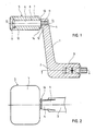
- - la figure 1 représente en vue de face en coupe une manivelle de moulinet de pêche connue ;
- - la figure 2 représente la manivelle de la figure 1 en vue de dessus ;
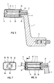
- - la figure 3 représente en vue de face en coupe une manivelle de moulinet selon la présente invention, dans un premier mode de réalisation ;
- - la figure 4 représente la manivelle de la figure 3 en vue de dessus ;
- - la figure 5 représente en vue de face en coupe une manivelle de moulinet de pêche selon la présente invention dans un second mode de réalisation ;
- - la figure 6 représente en vue de face en coupe une manivelle de moulinet de pêche selon la présente invention dans un troisième mode de réalisation ;
- - la figure 7 est une coupe transversale de la poignée selon le plan A de la figure 6 ; et
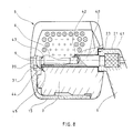
- - la figure 8 représente en vue de dessus en coupe une manivelle de moulinet de pêche selon l'invention dans un quatrième mode de réalisation.
- - Figure 1 shows a sectional front view of a known fishing reel crank;
- - Figure 2 shows the crank of Figure 1 in top view;
- - Figure 3 shows a sectional front view of a crank reel according to the present invention, in a first embodiment;
- - Figure 4 shows the crank of Figure 3 in top view;
- - Figure 5 shows a sectional front view of a fishing reel crank according to the present invention in a second embodiment;
- - Figure 6 shows a sectional front view of a fishing reel crank according to the present invention in a third embodiment;
- - Figure 7 is a cross section of the handle along the plane A of Figure 6; and
- - Figure 8 shows a top view in section of a fishing reel crank according to the invention in a fourth embodiment.
Les figures 1 et 2 sont destinées à mieux faire comprendre les problèmes mentionnés précédemment, qui apparaissent dans les moulinets de pêche connus.Figures 1 and 2 are intended to better understand the problems mentioned above, which appear in known fishing reels.
Ces figures illustrent une forme de manivelle de moulinet de pêche connue, comportant un bras radial 1 dont une première extrémité 2 porte l'arbre de rotation principal 3 de manivelle, et dont la seconde extrémité 4 porte une poignée 5 montée rotative sur le bras selon un arbre de rotation axial de poignée. L'arbre de rotation principal 3 de manivelle se développe selon une direction I - I généralement perpendiculaire à la direction longitudinale de bobine de moulinet et de canne à pêche, et est relié aux organes habituels de bobinage du fil à pêche sur la bobine de moulinet. L'arbre de rotation principal 3 de manivelle tourillonne donc dans le corps de moulinet, non représenté sur les figures, de manière connue en soi.These figures illustrate a form of known fishing reel crank, comprising a
La poignée 5 est rotative autour d'un axe II - II généralement parallèle à la direction I - I de l'arbre de rotation principal de manivelle, ou direction axiale.The
La poignée 5 est généralement reliée au bras radial 1 par une vis épaulée 6 : la poignée 5 est constituée d'un corps rigide 7 percé de part en part par un alésage axial 8 ; la vis épaulée 6 traverse à faible jeu l'alésage 8, et sa tête 9 porte contre une première facette d'extrémité 10 du corps rigide 7 de manivelle ; l'extrémité 11 de la tige de vis 6 est vissée dans un alésage taraudé correspondant de la seconde extrémité 4 de bras radial 1 ; l'épaulement intermédiaire 12 de la vis 6 porte contre une facette 13 de bras radial 1. Un jeu suffisant est ménagé pour permettre une légère translation axiale du corps 7 de poignée sur la tige de vis épaulée 6, entre la tête 9 et la facette de bras radial 13. On a représenté, sur les figures 1 et 2, l'apparition d'une gorge annulaire périphérique 14 entre le corps rigide de poignée et la seconde extrémité 4 de bras radial 1. Le fil de pêche, dans certaines phases d'utilisation du matériel, risque de s'enrouler et de se coincer dans la gorge 14.The
Dans le mode de réalisation représenté sur les figures 3 et 4, le moulinet selon l'invention comporte également les éléments principaux des manivelles de moulinet connues représentées sur les figures 1 et 2, éléments principaux qui ont été repris avec les mêmes références numériques, et notamment : bras radial 1, arbre de rotation principal de manivelle 3, poignée 5, corps rigide 7, vis de liaison 6.In the embodiment shown in FIGS. 3 and 4, the reel according to the invention also includes the main elements of the known reel cranks shown in FIGS. 1 and 2, main elements which have been used with the same reference numbers, and in particular:
Toutefois, dans ce mode de réalisation, le corps rigide 7 de poignée est interne, et est recouvert d'une capote 15 en élastomère recouvrant simultanément les faces périphériques 16 et la face d'extrémité 17 du corps rigide 7. Lors des chutes, la capote 15 en matériau élastique forme une couche protectrice amortissant les chocs.However, in this embodiment, the
On comprend que la capote 15, qui recouvre la face périphérique 16 du corps rigide 7, forme par elle-même la surface de préhension de la manivelle. Il en résulte que ladite surface de préhension est déformable et adhérente, ce qui facilite sa manipulation et la rend particulièrement agréable. La capote 15 s'oppose en outre à la pénétration de corps étrangers dans l'alésage 8 de poignée, car elle forme une paroi continue et étanche recouvrant la zone d'extrémité occupée par la tête 9 de vis.It is understood that the
La surface périphérique 16 du corps rigide 7 de poignée comporte avantageusement des aspérités telles que l'excroissance d'extrémité 18 et l'excroissance opposée 19, coopérant avec la surface interne de capote 15 pour éviter l'arrachement intempestif de ladite capote. La capote est adaptée sous tension sur le corps rigide 7, et est retenue sur le corps par l'effet de son élasticité. La capote 15 est ainsi facilement interchangeable. Elle comporte, sur sa face externe périphérique, des aspérités schématiquement représentées par des lignes axiales 20 sur la figure 4, qui augmentent l'adhérence entre la poignée et les doigts de l'utilisateur. A la fin d'une saison de pêche, si lesdites aspérités 20 sont usées, il est possible de remédier facilement à ce défaut en changeant la capote 15.The
Selon ce mode de réalisation représenté sur les figures 3 et 4, la liaison entre la poignée 5 et le bras radial 1 s'effectue selon une structure nouvelle et avantageuse. La seconde extrémité 4 de bras radial 1 comporte une portion axiale externe 21, s'étendant parallèlement à l'axe II - II de manivelle, laquelle portion axiale externe 21 est prolongée par la poignée. La portion axiale externe 21 présente une section transversale SE inférieure à la section SP de poignée. La portion axiale externe 21 de bras est prolongée par une portion axiale interne de bras 22, de section SI, et se raccordant par sa première extrémité en bout de portion axiale externe 21. La seconde extrémité 23 de portion axiale interne 22 forme un épaulement limitant le déplacement axial de la poignée 5 en direction du bras radial 1. La portion axiale interne 22 est logée dans un alésage 24 d'extrémité de poignée. La section SE de portion axiale externe 21 est inférieure ou égale à la section SI de portion axiale interne 22 de bras. De cette manière, l'épaulement formé par la seconde extrémité 23 de portion axiale interne, qui limite le déplacement axial de poignée en direction du bras radial, occupe une position intermédiaire à l'intérieur de la poignée, c'est-à-dire une position non apparente et non accessible par le fil de pêche. Il en résulte que le fil de pêche ne rique pas de s'enrouler et de se coincer entre ledit épaulement 23 et la poignée.According to this embodiment shown in Figures 3 and 4, the connection between the
Dans le mode de réalisation représenté, la liaison entre la poignée 5 et le bras radial 1 est également assurée par une vis axiale 6, dont la tête 9 limite le déplacement axial de la poignée à l'écart du bras 1, et dont l'extrémité 11 est vissée dans un alésage taraudé de la seconde extrémité 4 de bras radial. Dans ce mode de réalisation, la vis 6 ne comporte pas d'épaulement intermédiaire, mais coopère avec une douille épaulée 25. La douille 25 comprend un corps tubulaire, traversé par la tige de vis 6, dont la première extrémité est en appui sur la tête 9 de vis, et dont la seconde extrémité comporte un épaulement de douille 26 formant surface d'appui contre la seconde extrémité 23 de la portion axiale 22 de bras radial 1. La douille 25 limite le vissage de la vis 6 dans l'alésage taraudé du bras radial. La présence de l'épaulement de douille 26, définissant une surface d'appui plus importante, limite l'écrasement de la matière formant l'extrémité de bras radial lors du serrage de la vis 6, et contribue à la résistance aux chocs. Ainsi, la douille 25 est en appui d'une part sur la tête 9 de vis et d'autre part sur l'épaulement 23 d'extrémité de bras radial 1. Dans ce mode de réalisation, on laisse un faible jeu pour permettre un léger déplacement axial du corps rigide 7 de poignée sur la douille 25, entre la tête 9 de vis et l'épaulement 26 de douille.In the embodiment shown, the connection between the
De préférence, la portion axiale interne 22 de bras radial, ou portion pénétrant dans l'alésage 24 de poignée, doit avoir une longueur égale à plusieurs fois le diamètre du fil de pêche.Preferably, the internal
De même, de préférence, la portion axiale externe 21 de bras radial doit avoir une longueur égale à plusieurs fois le diamètre du fil de pêche. On évite ainsi les coincements du fil de pêche entre la poignée et le bras radial.Likewise, preferably, the external
On remarquera que la structure de liaison entre la poignée 5 et le bras radial 1 telle que représentée sur la figure 3 conduit à augmenter sensiblement la longueur de la portion de bras radial 1 dans laquelle pénètre la vis 6. Cette partie est en effet constituée d'une part par la portion axiale externe 21 de bras radial, et également par la portion axiale interne 22 du bras radial. Il en résulte une augmentation sensible de la résistance mécanique de cette liaison.It will be noted that the connection structure between the
Dans les modes de réalisations représentés sur les figures 5 à 7, la liaison entre la poignée 5 et le bras radial 1 comporte les mêmes éléments que dans le mode de réalisation de la figure 3, mais comporte en outre des moyens élastiques interposés entre la portion axiale de bras et la poignée, pour repousser la poignée en appui contre la base de la tête 9 de vis, à l'opposé du bras radial.In the embodiments shown in Figures 5 to 7, the connection between the
Dans le mode de réalisation de la figure 5, les moyens élastiques comprennent un anneau torique 30 en élastomère, logé entre la seconde extrémité 23 de portion axiale interne 22 de bras formant épaulement, et entre le corps rigide 7 de poignée. Le serrage de la vis 6 provoque un léger écrasement de l'anneau torique 30, qui fait ainsi office d'organe élastique repoussant la poignée 5 contre la tête de vis 9. On remarquera que l'anneau torique 30 fait simultanément office de joint d'étanchéité, limitant la pénétration d'organes étrangers dans la poignée, à l'intérieur de l'alésage 8. De préférence, l'anneau torique 30 est disposé en périphérie de l'épaulement 26 de la douille 25, de sorte que ledit épaulement 26 assure le centrage de l'anneau torique 30 et limite son écrasement.In the embodiment of Figure 5, the elastic means comprise an elastomeric O-
Dans le mode de réalisation des figures 6 et 7, les moyens élastiques comprennent une ou plusieurs languettes axiales, par exemple quatre languettes 31, 32, 33 et 34, dépassant de la face interne de paroi d'extrémité 35 de la capote 15, et conformées pour s'appuyer élastiquement sur la tête 9 de vis. Les languettes élastiques 31 - 34 assurent un rattrapage de jeu dans un sens préférentiel, évitant l'effet de grelot. De plus, en cas de choc latéral, la déformation supplémentaire engendrée absorbe l'énergie.In the embodiment of FIGS. 6 and 7, the elastic means comprise one or more axial tongues, for example four
Dans la variante représentée sur la figure 8, l'arbre de rotation de poignée est constitué d'un arbre creux 40, noyé à sa première extrémité 41 dans le bras 1 de manivelle, et comportant à sa seconde extrémité un trou borgne 42 taraudé dans lequel vient se visser une vis 6 à tête 9 lisse bombée. Les surfaces de liaison entre la portion axiale 21 du bras radial et le corps de poignée sont similaires à celles des modes de réalisation précédents, c'est-à-dire qu'elles comportent une portion axiale externe 21, une portion axiale interne 22, une seconde extrémité 23 de portion axiale interne formant épaulement limitant le déplacement axial de la poignée 5 en direction du bras radial 1. La base 43 de la tête 9 de vis limite le déplacement axial de la poignée 5 à l'écart du bras 1. Le jeu axial de la poignée 5 entre la base 43 de la tête 9 de vis et l'épaulement 23 est ajusté par le moyen d'une rondelle 44 d'épaisseur appropriée insérée entre la base 43 de la tête 9 de vis et la face frontale correspondante 45 du corps rigide 7 de poignée. Une languette élastique 31, éventuellement associée à d'autres languettes élastiques similaires, dépasse de la face interne de paroi d'extrémité 35 de la capote 15 recouvrant les faces périphériques et la face d'extrémité du corps rigide 7. La languette élastique 31 vient porter sur la face d'extrémité bombée de la tête 9 lisse de vis, pour repousser la poignée 5 à l'écart du bras 1. Cette variante assure également le rattrapage de jeu dans le sens préférentiel, évitant l'effet de grelot, et permet un reglage précis du jeu axial par un choix approprié de la rondelle 44.In the variant shown in Figure 8, the handle rotation shaft consists of a
La présente invention n'est pas limitée aux modes de réalisation qui ont été explicitement décrits, mais elle en inclut les diverses variantes et généralisations contenues dans le domaine des revendications ci-après.The present invention is not limited to the embodiments which have been explicitly described, but it includes the various variants and generalizations thereof contained in the field of claims below.
Claims (10)
- la poignée (5) comporte un corps rigide interne (7) percé de l'alésage traversant (8) qui débouche sur ses faces d'extrémité,
- le corps rigide (7) est recouvert d'une capote (15) en élastomère recouvrant simultanément les faces périphériques (16) et la face d'extrémité (17) du corps rigide (7),
de sorte que la poignée (5) présente des propriétés d'amortissement mécanique aux chocs, présente une surface de préhension déformable et adhérente, la capote (15) s'opposant en outre à la pénétration de corps étrangers dans l'alésage (8) traversant de poignée.1 - Fishing reel comprising a crank for actuating the fishing line winding members, the crank comprising a radial arm (1) of which a first end (2) carries the main rotation shaft (3) for connecting crank on the reel body, and a second end (4) of which carries a handle (5) rotatably mounted on the arm according to an axial rotation shaft (6) parallel to the main rotation shaft (3) of the crank, the radial arm (1) comprising an axial portion (6) forming a handle rotation shaft and inserted into a through bore (8) of the handle, characterized in that:
the handle (5) comprises an internal rigid body (7) pierced with the through bore (8) which opens on its end faces,
the rigid body (7) is covered with an elastomer hood (15) simultaneously covering the peripheral faces (16) and the end face (17) of the rigid body (7),
so that the handle (5) has mechanical shock absorption properties, has a deformable and adherent gripping surface, the hood (15) further opposing the penetration of foreign bodies into the bore (8) through handle.
- la seconde extrémité (4) de bras radial comporte une portion axiale externe (21) prolongée par la poignée (5), et de section transversale (SE) inférieure à la section (SP) de poignée, le bras radial (1) comportant un épaulement (23) limitant le déplacement relatif axial de la poignée en direction du bras,
- la portion axiale externe (21) de bras est prolongée par une portion axiale interne (22) de bras, de section (SI), se raccordant par sa première extrémité en bout de la portion axiale externe (21),
- l'épaulement (23) est formé par la second extrémité de portion axiale interne (22) de bras,
- la portion axiale interne (22) de bras est logée dans un alésage (24) d'extrémité de poignée,
- la section (SE) de portion axiale externe (21) est inférieure ou égale à la section (SI) de portion axiale interne (22) de bras,
de sorte que l'épaulement de bras (23) occupe une position intermédiaire à l'intérieur de la poignée, et que le fil de pêche ne risque pas de s'enrouler et de se coincer entre l'épaulement de bras (23) et la poignée (5).3 - Reel according to one of claims 1 or 2, characterized in that:
- The second end (4) of the radial arm has an external axial portion (21) extended by the handle (5), and of cross section (SE) less than the handle section (SP), the radial arm (1) comprising a shoulder (23) limiting the relative axial displacement of the handle in the direction of the arm,
the external axial portion (21) of the arm is extended by an internal axial portion (22) of the arm, of section (SI), which is connected by its first end to the end of the external axial portion (21),
the shoulder (23) is formed by the second end of the internal axial portion (22) of the arm,
the internal axial portion (22) of the arm is housed in a bore (24) at the end of the handle,
the section (SE) of the external axial portion (21) is less than or equal to the section (SI) of the internal axial portion (22) of the arm,
so that the arm shoulder (23) occupies an intermediate position inside the handle, and the fishing line is not likely to wind up and become trapped between the arm shoulder (23) and the handle (5).
Applications Claiming Priority (2)
| Application Number | Priority Date | Filing Date | Title |
|---|---|---|---|
| FR8813453A FR2637458B1 (en) | 1988-10-07 | 1988-10-07 | FISHING REEL HANDLE |
| FR8813453 | 1988-10-07 |
Publications (2)
| Publication Number | Publication Date |
|---|---|
| EP0363290A1 true EP0363290A1 (en) | 1990-04-11 |
| EP0363290B1 EP0363290B1 (en) | 1992-11-19 |
Family
ID=9370967
Family Applications (1)
| Application Number | Title | Priority Date | Filing Date |
|---|---|---|---|
| EP89420376A Expired - Lifetime EP0363290B1 (en) | 1988-10-07 | 1989-10-04 | Crank for a fishing reel |
Country Status (3)
| Country | Link |
|---|---|
| US (1) | US5150853A (en) |
| EP (1) | EP0363290B1 (en) |
| FR (1) | FR2637458B1 (en) |
Cited By (2)
| Publication number | Priority date | Publication date | Assignee | Title |
|---|---|---|---|---|
| US5150853A (en) * | 1988-10-07 | 1992-09-29 | Jean Bernard | Crank-handle for a fishing reel |
| US5328122A (en) * | 1991-08-23 | 1994-07-12 | Daiwa Seiko, Inc. | Handle for fishing reel |
Families Citing this family (15)
| Publication number | Priority date | Publication date | Assignee | Title |
|---|---|---|---|---|
| US5255573A (en) * | 1992-01-22 | 1993-10-26 | Harken, Inc. | Winch handle |
| EP0575929B1 (en) * | 1992-06-25 | 1997-05-21 | D.A.M. DEUTSCHE ANGELGERÄTE MANUFAKTUR HELLMUTH KUNTZE GMBH & CO. KG | Handle for or on a crank for a fishing reel |
| US5660344A (en) * | 1994-04-28 | 1997-08-26 | Testa; Thomas J. | Fishing reel handle |
| US5513544A (en) * | 1994-07-07 | 1996-05-07 | J. W. Winco, Inc. | Locking, retracting mechanism for crank handles |
| JP3457145B2 (en) * | 1996-08-08 | 2003-10-14 | ダイワ精工株式会社 | Fishing reel |
| JP3504463B2 (en) * | 1997-07-10 | 2004-03-08 | ダイワ精工株式会社 | Fishing reel handle |
| JP4015957B2 (en) * | 2003-01-20 | 2007-11-28 | 株式会社シマノ | Spinning reel handle assembly |
| US9661833B2 (en) | 2009-04-10 | 2017-05-30 | Ben Huang | Multi-layered grip |
| JP2010273629A (en) * | 2009-05-29 | 2010-12-09 | Shimano Components Malaysia Sdn Bhd | Handle assembly of fishing reel |
| ITMI20140074U1 (en) * | 2014-02-26 | 2015-08-26 | Elesa Spa | IMPROVED HANDLE. |
| EP3493871A4 (en) * | 2016-08-05 | 2020-04-08 | Merit Medical Systems, Inc. | Crank mechanism for balloon inflation device |
| US11160958B2 (en) | 2017-02-24 | 2021-11-02 | Merit Medical Systems, Inc. | Medical inflation systems and methods |
| US10653124B2 (en) * | 2017-05-03 | 2020-05-19 | Winn Incorporated | Reel component and method of manufacturing same |
| JP6956602B2 (en) * | 2017-11-13 | 2021-11-02 | 株式会社シマノ | Handle knob of fishing reel and reel for fishing |
| USD958337S1 (en) | 2019-07-26 | 2022-07-19 | Merit Medical Systems, Inc. | Medical inflation device |
Citations (1)
| Publication number | Priority date | Publication date | Assignee | Title |
|---|---|---|---|---|
| FR2487637A1 (en) * | 1980-07-31 | 1982-02-05 | Mitchell Sa | Fishing line reel with rotatable drum - has friction brake actuated by member with compressible shoe acting against part fixed to frame |
Family Cites Families (11)
| Publication number | Priority date | Publication date | Assignee | Title |
|---|---|---|---|---|
| US2438287A (en) * | 1946-01-03 | 1948-03-23 | Hypnarowski Adam | Fishing reel |
| US3989204A (en) * | 1968-01-05 | 1976-11-02 | Carpano & Pons S.A. | Fly fishing reel |
| US3806060A (en) * | 1971-09-15 | 1974-04-23 | C Valentine | Fishing reel with planetary drive |
| SE369825B (en) * | 1973-05-11 | 1974-09-23 | Abu Ab | |
| FR2278257A1 (en) * | 1974-06-05 | 1976-02-13 | Mitchell Sa | Handle for fishing reel - has hand grip pivotal about axis perpendicular to support arm axis |
| US4155517A (en) * | 1977-01-24 | 1979-05-22 | Ryobi Limited | Fishing spinning reels |
| US4138075A (en) * | 1977-09-08 | 1979-02-06 | Korten Chauncey F | Combination knob for fishing reels |
| US4220054A (en) * | 1979-02-02 | 1980-09-02 | Kuhlman Diecasting Company | Crank handle assembly |
| JPS6180664U (en) * | 1984-11-02 | 1986-05-29 | ||
| US4830306A (en) * | 1986-08-25 | 1989-05-16 | Ryobi Ltd. | Fishing reel leg with soft cover |
| FR2637458B1 (en) * | 1988-10-07 | 1991-01-04 | Mitchell Sports | FISHING REEL HANDLE |
-
1988
- 1988-10-07 FR FR8813453A patent/FR2637458B1/en not_active Expired - Lifetime
-
1989
- 1989-10-03 US US07/416,518 patent/US5150853A/en not_active Expired - Fee Related
- 1989-10-04 EP EP89420376A patent/EP0363290B1/en not_active Expired - Lifetime
Patent Citations (1)
| Publication number | Priority date | Publication date | Assignee | Title |
|---|---|---|---|---|
| FR2487637A1 (en) * | 1980-07-31 | 1982-02-05 | Mitchell Sa | Fishing line reel with rotatable drum - has friction brake actuated by member with compressible shoe acting against part fixed to frame |
Cited By (3)
| Publication number | Priority date | Publication date | Assignee | Title |
|---|---|---|---|---|
| US5150853A (en) * | 1988-10-07 | 1992-09-29 | Jean Bernard | Crank-handle for a fishing reel |
| US5328122A (en) * | 1991-08-23 | 1994-07-12 | Daiwa Seiko, Inc. | Handle for fishing reel |
| US5429317A (en) * | 1991-08-23 | 1995-07-04 | Daiwa Seiko, Inc. | Handle for fishing reel |
Also Published As
| Publication number | Publication date |
|---|---|
| FR2637458A1 (en) | 1990-04-13 |
| FR2637458B1 (en) | 1991-01-04 |
| US5150853A (en) | 1992-09-29 |
| EP0363290B1 (en) | 1992-11-19 |
Similar Documents
| Publication | Publication Date | Title |
|---|---|---|
| EP0363290B1 (en) | Crank for a fishing reel | |
| EP0860112B1 (en) | Watertight fishing reel | |
| EP0703376A2 (en) | Bicycle hub with freewheel | |
| EP0631072A1 (en) | Seal for rotating shaft | |
| CA2664721C (en) | Actuator having main rod and auxiliary rod | |
| EP0976598B1 (en) | Check valve for fuel tank | |
| EP0466994A1 (en) | Device for forming seal between two components whilst allowing a relative rotation of the components | |
| EP2110719B1 (en) | Shock absorber for an oscillating mass | |
| CH636415A5 (en) | BOLT AND NUT ASSEMBLY AVOIDING LOOSING. | |
| EP0479228B1 (en) | Throttle valve to limit the gas flow snap variations in a duct | |
| FR2816016A1 (en) | TORQUE LIMITER | |
| EP0285830B1 (en) | Fishing device | |
| EP0179726B1 (en) | Releasable spool for fishing reels | |
| EP0981478B1 (en) | Rotor blade, in particular for helicopter antitorque tail rotor | |
| EP0862732B1 (en) | Bourdon tube pressure gauge | |
| FR2765454A1 (en) | REAR BRAKE FISHING REEL WITH INTERCHANGEABLE WIRE RESERVE | |
| FR2669320A1 (en) | MECHANICAL CORKSCREW. | |
| EP1059466B1 (en) | Engine mount with non-elastic wire movement limiter | |
| FR2622768A1 (en) | ASSEMBLY FOR FIXING A LINE TO A FISHING ROD END | |
| EP1659459B1 (en) | Protection device for the access to the winding mechanism of a pocket watch | |
| FR2479374A1 (en) | Seal for ball or roller bearing - has intermediate lip with divided contact region arranged between inner and outer lips | |
| EP0202156A1 (en) | Anular sealing device, especially for valves or taps | |
| FR2714703A3 (en) | Screw and nut with ball bearing threaded interconnection | |
| EP0369904A1 (en) | Fishing reel being under control of a bail arm | |
| FR2689256A1 (en) | Watch crown. |
Legal Events
| Date | Code | Title | Description |
|---|---|---|---|
| PUAI | Public reference made under article 153(3) epc to a published international application that has entered the european phase |
Free format text: ORIGINAL CODE: 0009012 |
|
| AK | Designated contracting states |
Kind code of ref document: A1 Designated state(s): FR GB IT |
|
| 17P | Request for examination filed |
Effective date: 19900709 |
|
| RAP3 | Party data changed (applicant data changed or rights of an application transferred) |
Owner name: MITCHELL SPORTS |
|
| 17Q | First examination report despatched |
Effective date: 19920330 |
|
| GRAA | (expected) grant |
Free format text: ORIGINAL CODE: 0009210 |
|
| AK | Designated contracting states |
Kind code of ref document: B1 Designated state(s): FR GB IT |
|
| PG25 | Lapsed in a contracting state [announced via postgrant information from national office to epo] |
Ref country code: IT Free format text: LAPSE BECAUSE OF FAILURE TO SUBMIT A TRANSLATION OF THE DESCRIPTION OR TO PAY THE FEE WITHIN THE PRE;WARNING: LAPSES OF ITALIAN PATENTS WITH EFFECTIVE DATE BEFORE 2007 MAY HAVE OCCURRED AT ANY TIME BEFORE 2007. THE CORRECT EFFECTIVE DATE MAY BE DIFFERENT FROM THE ONE RECORDED.SCRIBED TIME-LIMIT Effective date: 19921119 |
|
| GBT | Gb: translation of ep patent filed (gb section 77(6)(a)/1977) |
Effective date: 19930113 |
|
| PLBE | No opposition filed within time limit |
Free format text: ORIGINAL CODE: 0009261 |
|
| STAA | Information on the status of an ep patent application or granted ep patent |
Free format text: STATUS: NO OPPOSITION FILED WITHIN TIME LIMIT |
|
| PG25 | Lapsed in a contracting state [announced via postgrant information from national office to epo] |
Ref country code: GB Effective date: 19931004 |
|
| 26N | No opposition filed | ||
| GBPC | Gb: european patent ceased through non-payment of renewal fee |
Effective date: 19931004 |
|
| PG25 | Lapsed in a contracting state [announced via postgrant information from national office to epo] |
Ref country code: FR Effective date: 19940630 |
|
| REG | Reference to a national code |
Ref country code: FR Ref legal event code: ST |