EP0363244B1 - Sytème de contrôle actif selon trois axes de l'attitude d'un satellite géostationnaire - Google Patents
Sytème de contrôle actif selon trois axes de l'attitude d'un satellite géostationnaire Download PDFInfo
- Publication number
- EP0363244B1 EP0363244B1 EP89402568A EP89402568A EP0363244B1 EP 0363244 B1 EP0363244 B1 EP 0363244B1 EP 89402568 A EP89402568 A EP 89402568A EP 89402568 A EP89402568 A EP 89402568A EP 0363244 B1 EP0363244 B1 EP 0363244B1
- Authority
- EP
- European Patent Office
- Prior art keywords
- detectors
- satellite
- axis
- mode
- detector
- Prior art date
- Legal status (The legal status is an assumption and is not a legal conclusion. Google has not performed a legal analysis and makes no representation as to the accuracy of the status listed.)
- Expired - Lifetime
Links
- 238000000034 method Methods 0.000 title description 10
- 238000012937 correction Methods 0.000 claims description 28
- 235000019892 Stellar Nutrition 0.000 claims description 26
- 238000012545 processing Methods 0.000 claims description 20
- 238000005259 measurement Methods 0.000 claims description 14
- 230000004083 survival effect Effects 0.000 claims description 9
- 238000007781 pre-processing Methods 0.000 claims description 4
- 230000006641 stabilisation Effects 0.000 description 4
- 230000008901 benefit Effects 0.000 description 3
- 238000010586 diagram Methods 0.000 description 3
- 230000005855 radiation Effects 0.000 description 3
- 238000011105 stabilization Methods 0.000 description 3
- 238000012546 transfer Methods 0.000 description 3
- 238000004364 calculation method Methods 0.000 description 2
- 230000015556 catabolic process Effects 0.000 description 2
- 238000012423 maintenance Methods 0.000 description 2
- 230000014759 maintenance of location Effects 0.000 description 2
- 230000003071 parasitic effect Effects 0.000 description 2
- 230000008569 process Effects 0.000 description 2
- 239000003380 propellant Substances 0.000 description 2
- 241000287107 Passer Species 0.000 description 1
- 241001282135 Poromitra oscitans Species 0.000 description 1
- 206010048232 Yawning Diseases 0.000 description 1
- 230000003247 decreasing effect Effects 0.000 description 1
- 238000009795 derivation Methods 0.000 description 1
- 238000001514 detection method Methods 0.000 description 1
- 235000021183 entrée Nutrition 0.000 description 1
- 238000010304 firing Methods 0.000 description 1
- 230000006872 improvement Effects 0.000 description 1
- 230000003287 optical effect Effects 0.000 description 1
- 238000011084 recovery Methods 0.000 description 1
- 230000008685 targeting Effects 0.000 description 1
Images


Classifications
-
- B—PERFORMING OPERATIONS; TRANSPORTING
- B64—AIRCRAFT; AVIATION; COSMONAUTICS
- B64G—COSMONAUTICS; VEHICLES OR EQUIPMENT THEREFOR
- B64G1/00—Cosmonautic vehicles
- B64G1/22—Parts of, or equipment specially adapted for fitting in or to, cosmonautic vehicles
- B64G1/24—Guiding or controlling apparatus, e.g. for attitude control
- B64G1/36—Guiding or controlling apparatus, e.g. for attitude control using sensors, e.g. sun-sensors, horizon sensors
-
- B—PERFORMING OPERATIONS; TRANSPORTING
- B64—AIRCRAFT; AVIATION; COSMONAUTICS
- B64G—COSMONAUTICS; VEHICLES OR EQUIPMENT THEREFOR
- B64G1/00—Cosmonautic vehicles
- B64G1/22—Parts of, or equipment specially adapted for fitting in or to, cosmonautic vehicles
- B64G1/24—Guiding or controlling apparatus, e.g. for attitude control
- B64G1/244—Spacecraft control systems
-
- G—PHYSICS
- G09—EDUCATION; CRYPTOGRAPHY; DISPLAY; ADVERTISING; SEALS
- G09B—EDUCATIONAL OR DEMONSTRATION APPLIANCES; APPLIANCES FOR TEACHING, OR COMMUNICATING WITH, THE BLIND, DEAF OR MUTE; MODELS; PLANETARIA; GLOBES; MAPS; DIAGRAMS
- G09B9/00—Simulators for teaching or training purposes
- G09B9/02—Simulators for teaching or training purposes for teaching control of vehicles or other craft
- G09B9/52—Simulators for teaching or training purposes for teaching control of vehicles or other craft for teaching control of an outer space vehicle
-
- B—PERFORMING OPERATIONS; TRANSPORTING
- B64—AIRCRAFT; AVIATION; COSMONAUTICS
- B64G—COSMONAUTICS; VEHICLES OR EQUIPMENT THEREFOR
- B64G1/00—Cosmonautic vehicles
- B64G1/22—Parts of, or equipment specially adapted for fitting in or to, cosmonautic vehicles
- B64G1/24—Guiding or controlling apparatus, e.g. for attitude control
- B64G1/36—Guiding or controlling apparatus, e.g. for attitude control using sensors, e.g. sun-sensors, horizon sensors
- B64G1/361—Guiding or controlling apparatus, e.g. for attitude control using sensors, e.g. sun-sensors, horizon sensors using star sensors
-
- B—PERFORMING OPERATIONS; TRANSPORTING
- B64—AIRCRAFT; AVIATION; COSMONAUTICS
- B64G—COSMONAUTICS; VEHICLES OR EQUIPMENT THEREFOR
- B64G1/00—Cosmonautic vehicles
- B64G1/22—Parts of, or equipment specially adapted for fitting in or to, cosmonautic vehicles
- B64G1/24—Guiding or controlling apparatus, e.g. for attitude control
- B64G1/36—Guiding or controlling apparatus, e.g. for attitude control using sensors, e.g. sun-sensors, horizon sensors
- B64G1/363—Guiding or controlling apparatus, e.g. for attitude control using sensors, e.g. sun-sensors, horizon sensors using sun sensors
-
- B—PERFORMING OPERATIONS; TRANSPORTING
- B64—AIRCRAFT; AVIATION; COSMONAUTICS
- B64G—COSMONAUTICS; VEHICLES OR EQUIPMENT THEREFOR
- B64G1/00—Cosmonautic vehicles
- B64G1/22—Parts of, or equipment specially adapted for fitting in or to, cosmonautic vehicles
- B64G1/24—Guiding or controlling apparatus, e.g. for attitude control
- B64G1/36—Guiding or controlling apparatus, e.g. for attitude control using sensors, e.g. sun-sensors, horizon sensors
- B64G1/365—Guiding or controlling apparatus, e.g. for attitude control using sensors, e.g. sun-sensors, horizon sensors using horizon or Earth sensors
-
- B—PERFORMING OPERATIONS; TRANSPORTING
- B64—AIRCRAFT; AVIATION; COSMONAUTICS
- B64G—COSMONAUTICS; VEHICLES OR EQUIPMENT THEREFOR
- B64G1/00—Cosmonautic vehicles
- B64G1/22—Parts of, or equipment specially adapted for fitting in or to, cosmonautic vehicles
- B64G1/24—Guiding or controlling apparatus, e.g. for attitude control
- B64G1/36—Guiding or controlling apparatus, e.g. for attitude control using sensors, e.g. sun-sensors, horizon sensors
- B64G1/369—Guiding or controlling apparatus, e.g. for attitude control using sensors, e.g. sun-sensors, horizon sensors using gyroscopes as attitude sensors
Definitions
- the invention relates to controlling the attitude of a geostationary satellite stabilized along three axes.
- such a satellite is associated with a direct orthonormal reference frame (X, Y, Z) whose X axis (or West-East axis) is in principle tangent to the orbit, and Z, or geocentric axis, is directed towards Earth.
- the third axis, Y, or North-South axis, is perpendicular to the X and Z axes.
- the stabilization of the satellite according to these three axes supposes a control of the three types of drifts: the pitch around the North-South axis Y, the roll around the axis X, East-West, and the yaw around the axis geocentric Z.
- the classic architecture of a geostationary satellite includes a terrestrial detector (in practice of the infrared type), suitable for measuring pitch and roll, possibly combined with one or more solar detector (s). .
- the yaw angle is passively controlled using an inertia wheel with an axis of rotation perpendicular to the geocentric axis, in practice parallel to the Y axis.
- any parasitic torques due to misalignment of the orbit correction nozzles with respect to the axes of the satellite, are three orders of magnitude greater than the solar torques undergone in normal mode, and the gyroscopic rigidity associated with the flywheels passively controlling the yaw may be insufficient.
- the precision of the yaw control is critical when holding on to the post because the amplitude of the orbit correction maneuvers along the North-South axis is three orders of magnitude greater than that of the correction maneuvers d orbit along the East-West axis, so that a small error on the yaw angle, for example a few 1/10 of a degree, during North-South maneuvers induces parasitic maneuvers relative to the axis East-West which can be of the same order of magnitude as the normal orbit correction maneuvers to be carried out around this East-West axis. This can significantly disturb the retention of the satellite.
- the return to a 3-axis stabilization on the orbit can only start in a configuration in which the Sun, the Earth and the satellite are not aligned, the directions Satellite-Earth and Satellite-Sun preferably being perpendicular (at 6 a.m. and 6 p.m.), which can lead to maintenance in survival mode (and interruptions of the satellite mission) for several hours: this appears increasingly incompatible with the constraints of the missions that we want to entrust to the satellites.
- the invention aims to overcome the aforementioned drawbacks by active attitude control along the three axes.
- Document FR-2 522 614 of the C.N.E.S. describes a stellar pointing method well, but it is associated with a specific type of platform entirely different from a conventional geostationary platform. It supposes the division of the platform into two modules (payload module and service module), each of them being stabilized in a different way.
- the service module is inertially stabilized, the payload module pointing towards the Earth.
- document FR-2 532 911 from CNES describes a process for the apogee maneuver of a geostationary satellite which uses a stellar detector according to a process which however requires an unusual arrangement of the satellite having serious drawbacks: the nozzle apogee is inclined at an angle equal to the declination of the maneuver. All the impulses to be given must therefore be carried out with the same orientation (which is not the case in practice). In addition, the inclination given to the nozzle only allows the disturbing torques to be balanced for a given coefficient of filling of the propellant tanks. As they empty the couples disruptors increase.
- a star detector is a fairly heavy element (3 to 10 Kg), for which there is generally a need for redundancy for security reasons, which results in a significant penalty from the point of view of on-board weight; taking into account the short duration of use of this detector compared to the lifetime of the satellite, the disadvantage of its mass is often considered decisive and it is often abandoned to integrate it into an attitude control system.
- the invention aims to overcome these drawbacks by allowing active attitude control along the three axes, which is both precise and permanent while minimizing the complexity (mass and risk of breakdowns) of the attitude control system. associated.
- the system therefore uses, for a satellite with an otherwise conventional configuration (in particular from the point of view of nozzles and wheels), a terrestrial detector, a star detector targeting the Polar Star, the sensitive axis of which is parallel to the Y axis of the satellite and oriented towards the North, possibly combined with three solar detectors with large field of view.
- FIG. 1 schematically represents a satellite 1 describing an orbit 2 around the Earth.
- satellite 1 is associated with a reference frame XYZ whose axis X is tangent to orbit 2, and oriented in the direction in which the orbit is traversed (from West to East), and the Z axis is directed towards the Earth; the third Y axis is parallel to a North-South direction.
- the satellite has a platform carrying solar panels 3, reflectors 4 and propulsion nozzles of any suitable known type.
- the platform of this satellite comprises at least one terrestrial sensor oriented towards the Earth and shown diagrammatically in T1 as well as a plurality of solar detectors distributed in a plane parallel to the plane of the axes X and Z and coming successively opposite from the Sun as the satellite describes its orbit.
- Different configurations are known; by way of example, there are three solar detectors here, S1, S2, and S l'un, arranged one S la on the face facing the Earth and the others, S1 and S3, on the edges opposite this face .
- S1, S2, and S l'un there are three solar detectors here, S1, S2, and S l'un, arranged one S la on the face facing the Earth and the others, S1 and S3, on the edges opposite this face .
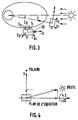
- the platform of this satellite is also provided, here on its north face (opposite the Y axis), with a fixed star detector P, of any suitable type, oriented according to the South-North axis.
- a fixed star detector P of any suitable type, oriented according to the South-North axis. This is for example a detector chosen from the SODERN or GALILEO range.
- detectors are sensitive to different ranges of radiation: terrestrial detectors are sensitive to infrared radiation from the Earth, solar detectors are formed from photoelectric cells and stellar detectors are based on bars or networks. Two-dimensional CCD ("Charge Coupled Device").
- Polar Star The choice of the Polar Star is explained by the fact that it is the only star of its magnitude to always be in the field of vision of a stellar detector fixedly mounted on the North face of a satellite and its recognition does not require sophisticated software.
- the terrestrial T1, solar S1 to S3 and stellar P detectors allow the angular orientation of the Earth, the Sun and the Polar Star to be noted at any time, respectively, in the reference frame linked to the satellite.
- the main originality of the system compared to the prior art lies not only in the presence of the star detector P on the North face but especially in its different implementation procedures adapted to the various types of mode, and therefore in associated processing chains. to these various modes.
- Each of these modes is associated with a particular processing chain, designated in FIG. 2 by the Roman numeral of the mode considered I, II, III or IV.
- Each of the processing chains I to IV comprise a preprocessing module 14, 15, 16 or 17 followed by a control and correction module 18, 19, 20 or 21.
- a yaw reference unit 22 is connected to each of the preprocessing modules 14 to 17 and is adapted to estimate at any time the position of the satellite in a predetermined inertial frame.
- This unit 22 contains a model for the evolution of the position of the Polar, and is connected to a telemetry unit 23 so that the parameters of this model are periodically refreshed as a function of information received from the ground.
- the modules 18 to 20 receive, in addition to the signals produced by the corresponding pre-processing modules 14 to 16, speed signals emitted, either by a module 24 for modeling the dynamics of the satellite receiving the signals from the detectors, or by gyrometers 25 .
- the output signal of the module 17 is transmitted to the telemetry unit for sending to the ground while the input of the control and correction module 21 is connected to this same telemetry unit for reception of correction orders calculated on the ground.
- the error signals from the terrestrial detector can be used directly without pretreatment in modules 14 to 17.
- this type of control law C i k i . ⁇ i + h i . ⁇ i is used for each of the axes to be controlled X, Y, and Z, in each of the modules 18 to 20, with coefficients h i and k i being predetermined for each axis and for each mode.
- the architecture of the detectors proposed by the invention offers increased security.
- the measurement of the yaw angle is imperative; it is supplied directly by the star detector.
- Another law of calculation determines the correction couples, with the same form as previously but with different parameters (the correction couples can be 2 to 3 orders of magnitude greater than those of the normal mode, and can go up to 10 ⁇ 2 Nm).
- the advantage of the method compared to the state of the art is that it makes it possible to avoid the use of a lace-up integrating gyroscope (hence gaining reliability, simplicity of implementation and precision without calibration) or the use of solar detectors for the yaw, which introduces constraints on the possible hours of operation and induces a penalty for consumption of additional propellants.
Landscapes
- Engineering & Computer Science (AREA)
- Remote Sensing (AREA)
- Aviation & Aerospace Engineering (AREA)
- Combustion & Propulsion (AREA)
- Radar, Positioning & Navigation (AREA)
- Chemical & Material Sciences (AREA)
- Theoretical Computer Science (AREA)
- Automation & Control Theory (AREA)
- Business, Economics & Management (AREA)
- Physics & Mathematics (AREA)
- Educational Administration (AREA)
- Educational Technology (AREA)
- General Physics & Mathematics (AREA)
- Control Of Position, Course, Altitude, Or Attitude Of Moving Bodies (AREA)
- Navigation (AREA)
Applications Claiming Priority (2)
| Application Number | Priority Date | Filing Date | Title |
|---|---|---|---|
| FR8813122 | 1988-10-06 | ||
| FR8813122A FR2637565B1 (fr) | 1988-10-06 | 1988-10-06 | Systeme de controle actif selon trois axes de l'attitude d'un satellite geostationnaire |
Publications (2)
| Publication Number | Publication Date |
|---|---|
| EP0363244A1 EP0363244A1 (fr) | 1990-04-11 |
| EP0363244B1 true EP0363244B1 (fr) | 1993-03-10 |
Family
ID=9370754
Family Applications (1)
| Application Number | Title | Priority Date | Filing Date |
|---|---|---|---|
| EP89402568A Expired - Lifetime EP0363244B1 (fr) | 1988-10-06 | 1989-09-19 | Sytème de contrôle actif selon trois axes de l'attitude d'un satellite géostationnaire |
Country Status (6)
| Country | Link |
|---|---|
| US (1) | US5054719A (ja) |
| EP (1) | EP0363244B1 (ja) |
| JP (1) | JP2844090B2 (ja) |
| CA (1) | CA2000215C (ja) |
| DE (1) | DE68905285T2 (ja) |
| FR (1) | FR2637565B1 (ja) |
Families Citing this family (30)
| Publication number | Priority date | Publication date | Assignee | Title |
|---|---|---|---|---|
| US5100084A (en) * | 1990-04-16 | 1992-03-31 | Space Systems/Loral, Inc. | Method and apparatus for inclined orbit attitude control for momentum bias spacecraft |
| WO1992003339A1 (en) * | 1990-08-22 | 1992-03-05 | Microcosm, Inc. | Satellite orbit maintenance system |
| FR2670746B1 (fr) * | 1990-12-21 | 1993-04-16 | Aerospatiale | Systeme de controle d'attitude pour satellite 3-axes,; notamment pour satellite d'observation. |
| US5349532A (en) * | 1992-04-28 | 1994-09-20 | Space Systems/Loral | Spacecraft attitude control and momentum unloading using gimballed and throttled thrusters |
| FR2691426B1 (fr) * | 1992-05-19 | 1997-09-19 | Aerospatiale | Procede et dispositif d'acquisition de la terre via la polaire pour satellite stabilise 3-axes en orbite de faible inclinaison. |
| FR2697651B1 (fr) * | 1992-10-29 | 1995-02-03 | Aerospatiale | Procédé et appareil de calibration des gyromètres d'un satellite stabilisé 3-axes. |
| US5562266A (en) * | 1992-10-29 | 1996-10-08 | Aerospatiale Societe Nationale Industrielle | Rate gyro calibration method and apparatus for a three-axis stabilized satellite |
| FR2699701B1 (fr) * | 1992-12-17 | 1995-03-24 | Aerospatiale | Procédé de contrôle d'attitude d'un satellite pointé vers un objet céleste et satellite adapté à sa mise en Óoeuvre. |
| US5452869A (en) * | 1992-12-18 | 1995-09-26 | Hughes Aircraft Company | On-board three-axes attitude determination and control system |
| RU2033949C1 (ru) * | 1993-02-09 | 1995-04-30 | Севастиян Дмитриевич Гнатюк | Автономная бортовая система управления космического аппарата "гасад" |
| US5412574A (en) * | 1993-05-14 | 1995-05-02 | Hughes Aircraft Company | Method of attitude determination using earth and star sensors |
| US5791598A (en) * | 1996-01-16 | 1998-08-11 | Globalstar L.P. and Daimler-Benz Aerospace AG | Dynamic bias for orbital yaw steering |
| FR2757824B1 (fr) * | 1996-12-31 | 1999-03-26 | Europ Propulsion | Procede et systeme de lancement de satellites sur des orbites non coplanaires en utilisant l'assistance gravitationnelle lunaire |
| US6285928B1 (en) | 2000-01-06 | 2001-09-04 | Space Systems/Loral, Inc. | Onboard attitude control using reaction wheels |
| US6439507B1 (en) * | 2000-05-05 | 2002-08-27 | Space Systems/Loral, Inc. | Closed-loop spacecraft orbit control |
| US6570528B1 (en) | 2001-11-09 | 2003-05-27 | The Boeing Company | Antenna system for multiple orbits and multiple areas |
| US20110005316A1 (en) * | 2005-07-12 | 2011-01-13 | Centro De Investigacon De Rotagcion Y Torque S.L | Acceleration systems for moving devices |
| US7454272B1 (en) * | 2005-08-25 | 2008-11-18 | Raytheon Company | Geostationary stationkeeping method |
| RU2454631C1 (ru) * | 2010-10-28 | 2012-06-27 | Государственное образовательное учреждение высшего профессионального образования Военно-космическая академия имени А.Ф. Можайского | Способ автономной навигации и ориентации космических аппаратов на основе виртуальных измерений зенитных расстояний звезд |
| RU2527632C2 (ru) * | 2012-12-27 | 2014-09-10 | Федеральное Государственное Автономное Образовательное Учреждение Высшего Профессионального Образования "Московский Физико-Технический Институт (Государственный Университет)" | Способ наземной имитации полета космических аппаратов в космосе |
| MX355863B (es) * | 2014-03-12 | 2018-05-03 | Nissan Motor | Dispositivo de operación de vehículo. |
| RU2558647C1 (ru) * | 2014-04-15 | 2015-08-10 | Открытое акционерное общество "Раменское приборостроительное конструкторское бюро" | Навигационный комплекс, использующий естественные и искусственные поля земли |
| DE102014211175A1 (de) | 2014-06-11 | 2015-12-17 | Continental Teves Ag & Co. Ohg | Verfahren und System zur Initialisierung eines Sensorfusionssystems |
| DE102014211164A1 (de) | 2014-06-11 | 2015-12-17 | Continental Teves Ag & Co. Ohg | Verfahren und System zur Anpassung eines Navigationssystems |
| US9746562B2 (en) * | 2014-06-30 | 2017-08-29 | The Boeing Company | Portable ground based augmentation system |
| FR3028031B1 (fr) * | 2014-10-29 | 2019-09-20 | Safran Electronics & Defense | Procede d'estimation d'un etat de navigation contraint en observabilite |
| EP3304234A4 (en) * | 2015-06-02 | 2019-01-16 | The Charles Stark Draper Laboratory, Inc. | SYSTEMS FOR QUICK PANS AND CALM FOR SMALL SATELLITES |
| FR3043455B1 (fr) * | 2015-11-10 | 2017-12-01 | Sagem Defense Securite | Procede d'elaboration d'une navigation et procede d'orientation d'un organe de visee a partir de cette navigation |
| RU2624408C2 (ru) * | 2015-12-01 | 2017-07-03 | Федеральное государственное казенное военное образовательное учреждение высшего профессионального образования "Военно-космическая академия имени А.Ф. Можайского" Министерства обороны Российской Федерации | Способ автономного оценивания изменений орбиты визируемого космического аппарата |
| RU2623667C1 (ru) * | 2016-04-18 | 2017-06-28 | Федеральное государственное бюджетное учреждение "Центральный научно-исследовательский институт Войск воздушно-космической обороны Минобороны России" (ФГБУ "ЦНИИ ВВКО Минобороны России") | Способ навигационных астрономических измерений координат местоположения подвижного объекта и устройство для его реализации |
Family Cites Families (12)
| Publication number | Priority date | Publication date | Assignee | Title |
|---|---|---|---|---|
| US3427453A (en) * | 1966-05-25 | 1969-02-11 | Rca Corp | System for switching the attitude reference of a satellite from a first celestial body to a second celestial body |
| US3996804A (en) * | 1975-02-19 | 1976-12-14 | Hughes Aircraft Company | Method for remotely determining the dynamic imbalance of and for changing the spin rate and center of gravity of a spinning body |
| DE2642061C2 (de) * | 1976-09-18 | 1983-11-24 | Messerschmitt-Bölkow-Blohm GmbH, 8000 München | Lageregelungs- und Bahnänderungsverfahren für einen dreiachsenstabilisierbaren Satelliten, insbesondere für einen geostationären Satelliten und Einrichtung zur Durchführung des Verfahrens |
| US4161780A (en) * | 1978-06-23 | 1979-07-17 | The United States Of America As Represented By The Secretary Of The Navy | Spin rate timing system |
| US4617634A (en) * | 1983-06-28 | 1986-10-14 | Mitsubishi Denki Kabushiki Kaisha | Artificial satellite attitude control system |
| JPS6171300A (ja) * | 1984-09-13 | 1986-04-12 | 三菱電機株式会社 | 人工衛星の姿勢角計算装置 |
| US4728061A (en) * | 1985-03-20 | 1988-03-01 | Space Industries, Inc. | Spacecraft operable in two alternative flight modes |
| FR2583873B1 (fr) * | 1985-06-20 | 1987-09-11 | Matra | Procede et dispositif d'injection de satellite sur orbite geostationnaire avec stabilisation suivant les trois axes |
| JP2518212B2 (ja) * | 1986-06-26 | 1996-07-24 | 日本電気株式会社 | 人工衛星の軌道制御方式 |
| FR2601159B1 (fr) * | 1986-07-04 | 1988-09-16 | Europ Agence Spatiale | Procedure de repointage rapide des satellites a pointage terrestre, et notamment des satellites geostationnaires de telecommunication a stabilisation par volant d'inertie |
| US4749157A (en) * | 1986-08-18 | 1988-06-07 | Hughes Aircraft Company | Spacecraft accelerometer auto-alignment |
| US4767084A (en) * | 1986-09-18 | 1988-08-30 | Ford Aerospace & Communications Corporation | Autonomous stationkeeping for three-axis stabilized spacecraft |
-
1988
- 1988-10-06 FR FR8813122A patent/FR2637565B1/fr not_active Expired - Fee Related
-
1989
- 1989-09-19 DE DE8989402568T patent/DE68905285T2/de not_active Expired - Lifetime
- 1989-09-19 EP EP89402568A patent/EP0363244B1/fr not_active Expired - Lifetime
- 1989-10-05 CA CA002000215A patent/CA2000215C/en not_active Expired - Fee Related
- 1989-10-05 JP JP1261231A patent/JP2844090B2/ja not_active Expired - Lifetime
- 1989-10-05 US US07/417,759 patent/US5054719A/en not_active Expired - Lifetime
Also Published As
| Publication number | Publication date |
|---|---|
| CA2000215A1 (en) | 1990-04-06 |
| JP2844090B2 (ja) | 1999-01-06 |
| FR2637565B1 (fr) | 1991-01-11 |
| FR2637565A1 (fr) | 1990-04-13 |
| EP0363244A1 (fr) | 1990-04-11 |
| DE68905285D1 (de) | 1993-04-15 |
| JPH02157913A (ja) | 1990-06-18 |
| CA2000215C (en) | 1993-12-21 |
| US5054719A (en) | 1991-10-08 |
| DE68905285T2 (de) | 1993-07-15 |
Similar Documents
| Publication | Publication Date | Title |
|---|---|---|
| EP0363244B1 (fr) | Sytème de contrôle actif selon trois axes de l'attitude d'un satellite géostationnaire | |
| EP0363243B1 (fr) | Procédé et système de contrôle autonome d'orbite d'un satellite géostationnaire | |
| EP0493143B1 (fr) | Système de contrôle d'attitude pour satellite stabilisé 3-axes, notamment pour satellite d'observation | |
| EP0603058B1 (fr) | Procédé de contrÔle d'attitude d'un satellite pointé vers un objet céleste et satellite adapté à sa mise en oeuvre | |
| EP2181923B1 (fr) | Procédé et système de désaturation des roues d'inertie d'un engin spatial | |
| EP0571239A1 (fr) | Procédé et dispositif d'acquisition de la Terre via la Polaire pour satellite stabilisé 3-axes en orbite de faible inclinaison | |
| EP0209429B1 (fr) | Procédé et dispositif d'injection de satellite sur orbite géostationnaire avec stabilisation suivant les trois axes | |
| EP0493228B1 (fr) | Procédé de réacquisition d'attitude par reconnaissance d'étoile pour satellite stabilisé 3-axes | |
| EP0199648B1 (fr) | Procédé et dispositif d'amortissement de nutation de satellite par commande d'orientation de masses présentant un produit d'inertie variable | |
| FR2689855A1 (fr) | Agencement et procédé pour le maintien coordonné en position d'un essaim de satellites géostationnaires. | |
| EP3921235B1 (fr) | Procédé de contrôle d'attitude d'un satellite en mode survie sans connaissance a priori de l'heure locale de l'orbite du satellite | |
| CA1267949A (fr) | Procedure de repointage rapide des satellites a pointage terrestre, et notamment des satellites geostationnaires de telecommunication a stabilisation par volant d'inertie | |
| EP0341130B1 (fr) | Procédé de basculement du moment d'inertie d'un corps rotatif libre dans l'espace jusqu'en une direction donnée | |
| EP0678732B1 (fr) | Procédé et appareil de calibration des gyromètres d'un satellite stabilisé 3-axes | |
| FR2859782A1 (fr) | Systemes d'armes | |
| FR2531547A1 (fr) | Systeme de controle d'attitude d'un satellite geostationnaire | |
| EP1635485B1 (fr) | Procédé de transmission optique entre un terminal embarqué sur un engin spatial et un terminal distant, et engin spatial adapté pour un tel procédé | |
| EP1569847B1 (fr) | Procede de pilotage solaire de vehicule spatial | |
| EP4183066B1 (fr) | Procédé d'émission de données par un engin spatial comportant un module d'émission laser | |
| FR3137190A1 (fr) | Manœuvre de satellites sans detecteurs de variation | |
| FR2532911A1 (fr) | Procede pour la correction d'orbite d'un satellite artificiel et dispositif correspondant | |
| JPS61163100A (ja) | 恒星トラツカ |
Legal Events
| Date | Code | Title | Description |
|---|---|---|---|
| PUAI | Public reference made under article 153(3) epc to a published international application that has entered the european phase |
Free format text: ORIGINAL CODE: 0009012 |
|
| AK | Designated contracting states |
Kind code of ref document: A1 Designated state(s): DE ES GB IT NL SE |
|
| 17P | Request for examination filed |
Effective date: 19900518 |
|
| 17Q | First examination report despatched |
Effective date: 19920508 |
|
| GRAA | (expected) grant |
Free format text: ORIGINAL CODE: 0009210 |
|
| AK | Designated contracting states |
Kind code of ref document: B1 Designated state(s): DE ES GB IT NL SE |
|
| PG25 | Lapsed in a contracting state [announced via postgrant information from national office to epo] |
Ref country code: IT Free format text: LAPSE BECAUSE OF FAILURE TO SUBMIT A TRANSLATION OF THE DESCRIPTION OR TO PAY THE FEE WITHIN THE PRE;WARNING: LAPSES OF ITALIAN PATENTS WITH EFFECTIVE DATE BEFORE 2007 MAY HAVE OCCURRED AT ANY TIME BEFORE 2007. THE CORRECT EFFECTIVE DATE MAY BE DIFFERENT FROM THE ONE RECORDED.SCRIBED TIME-LIMIT Effective date: 19930310 Ref country code: ES Free format text: THE PATENT HAS BEEN ANNULLED BY A DECISION OF A NATIONAL AUTHORITY Effective date: 19930310 Ref country code: NL Effective date: 19930310 Ref country code: SE Effective date: 19930310 |
|
| REF | Corresponds to: |
Ref document number: 68905285 Country of ref document: DE Date of ref document: 19930415 |
|
| GBT | Gb: translation of ep patent filed (gb section 77(6)(a)/1977) |
Effective date: 19930623 |
|
| NLV1 | Nl: lapsed or annulled due to failure to fulfill the requirements of art. 29p and 29m of the patents act | ||
| PLBE | No opposition filed within time limit |
Free format text: ORIGINAL CODE: 0009261 |
|
| STAA | Information on the status of an ep patent application or granted ep patent |
Free format text: STATUS: NO OPPOSITION FILED WITHIN TIME LIMIT |
|
| 26N | No opposition filed | ||
| REG | Reference to a national code |
Ref country code: GB Ref legal event code: IF02 |
|
| PGFP | Annual fee paid to national office [announced via postgrant information from national office to epo] |
Ref country code: GB Payment date: 20020904 Year of fee payment: 14 |
|
| PGFP | Annual fee paid to national office [announced via postgrant information from national office to epo] |
Ref country code: DE Payment date: 20020907 Year of fee payment: 14 |
|
| PG25 | Lapsed in a contracting state [announced via postgrant information from national office to epo] |
Ref country code: GB Free format text: LAPSE BECAUSE OF NON-PAYMENT OF DUE FEES Effective date: 20030919 |
|
| PG25 | Lapsed in a contracting state [announced via postgrant information from national office to epo] |
Ref country code: DE Free format text: LAPSE BECAUSE OF NON-PAYMENT OF DUE FEES Effective date: 20040401 |
|
| GBPC | Gb: european patent ceased through non-payment of renewal fee |
Effective date: 20030919 |