EP0362582A2 - Apparatus for granulating by freezing liquids - Google Patents
Apparatus for granulating by freezing liquids Download PDFInfo
- Publication number
- EP0362582A2 EP0362582A2 EP89116930A EP89116930A EP0362582A2 EP 0362582 A2 EP0362582 A2 EP 0362582A2 EP 89116930 A EP89116930 A EP 89116930A EP 89116930 A EP89116930 A EP 89116930A EP 0362582 A2 EP0362582 A2 EP 0362582A2
- Authority
- EP
- European Patent Office
- Prior art keywords
- drip
- nozzle
- bodies
- disc
- container
- Prior art date
- Legal status (The legal status is an assumption and is not a legal conclusion. Google has not performed a legal analysis and makes no representation as to the accuracy of the status listed.)
- Withdrawn
Links
Images
Classifications
-
- B—PERFORMING OPERATIONS; TRANSPORTING
- B01—PHYSICAL OR CHEMICAL PROCESSES OR APPARATUS IN GENERAL
- B01J—CHEMICAL OR PHYSICAL PROCESSES, e.g. CATALYSIS OR COLLOID CHEMISTRY; THEIR RELEVANT APPARATUS
- B01J2/00—Processes or devices for granulating materials, e.g. fertilisers in general; Rendering particulate materials free flowing in general, e.g. making them hydrophobic
-
- A—HUMAN NECESSITIES
- A23—FOODS OR FOODSTUFFS; TREATMENT THEREOF, NOT COVERED BY OTHER CLASSES
- A23L—FOODS, FOODSTUFFS, OR NON-ALCOHOLIC BEVERAGES, NOT COVERED BY SUBCLASSES A21D OR A23B-A23J; THEIR PREPARATION OR TREATMENT, e.g. COOKING, MODIFICATION OF NUTRITIVE QUALITIES, PHYSICAL TREATMENT; PRESERVATION OF FOODS OR FOODSTUFFS, IN GENERAL
- A23L3/00—Preservation of foods or foodstuffs, in general, e.g. pasteurising, sterilising, specially adapted for foods or foodstuffs
- A23L3/36—Freezing; Subsequent thawing; Cooling
- A23L3/363—Freezing; Subsequent thawing; Cooling the materials not being transported through or in the apparatus with or without shaping, e.g. in form of powder, granules, or flakes
-
- A—HUMAN NECESSITIES
- A23—FOODS OR FOODSTUFFS; TREATMENT THEREOF, NOT COVERED BY OTHER CLASSES
- A23L—FOODS, FOODSTUFFS, OR NON-ALCOHOLIC BEVERAGES, NOT COVERED BY SUBCLASSES A21D OR A23B-A23J; THEIR PREPARATION OR TREATMENT, e.g. COOKING, MODIFICATION OF NUTRITIVE QUALITIES, PHYSICAL TREATMENT; PRESERVATION OF FOODS OR FOODSTUFFS, IN GENERAL
- A23L3/00—Preservation of foods or foodstuffs, in general, e.g. pasteurising, sterilising, specially adapted for foods or foodstuffs
- A23L3/36—Freezing; Subsequent thawing; Cooling
- A23L3/37—Freezing; Subsequent thawing; Cooling with addition of or treatment with chemicals
- A23L3/375—Freezing; Subsequent thawing; Cooling with addition of or treatment with chemicals with direct contact between the food and the chemical, e.g. liquid nitrogen, at cryogenic temperature
-
- F—MECHANICAL ENGINEERING; LIGHTING; HEATING; WEAPONS; BLASTING
- F25—REFRIGERATION OR COOLING; COMBINED HEATING AND REFRIGERATION SYSTEMS; HEAT PUMP SYSTEMS; MANUFACTURE OR STORAGE OF ICE; LIQUEFACTION SOLIDIFICATION OF GASES
- F25C—PRODUCING, WORKING OR HANDLING ICE
- F25C1/00—Producing ice
Definitions
- the invention relates to a device for freeze-pelleting liquids by dropping them into a cooling liquid, which has a low temperature sufficient for freezing the drops, according to the preamble of patent claim 1.
- Freeze-pelletizing is used for the rapid freezing of liquid or viscous substances, for example sensitive liquids with organic components or of solutions and suspensions, such as those that occur in particular in biotechnology, in the food industry and in the chemical-pharmaceutical industry. Freezing sensitive liquids must be done as quickly and evenly as possible to prevent cold damage to the product.
- the freezing process is carried out by draining the liquids into a liquid coolant, e.g. Nitrogen.
- a liquid coolant e.g. Nitrogen.
- a prerequisite for gentle treatment of the products in the coolant is the same drop volume of approximately constant drop shape, so that on the one hand the residence time in the coolant can be as short as possible and still freeze all the drops completely.
- a process control ensures a uniform minimum dwell time of the drops in the coolant. After that, all drops in the coolant should be frozen through, and the freeze granules formed are e.g. automatically pumped out of the coolant.
- a special drip device is intended to ensure the optimal drop shape for the conditions set upon entry into the coolant and a uniform drop size.
- the drops are formed on a drip plate, which for example represents the lower end of a container for the product to be processed.
- the drip plate has nozzle-like openings through which the liquid Product escapes into a gas atmosphere or into a light vacuum under the influence of the static pressure or under the influence of external pressure.
- the drip plate is arranged at a certain critical height above the surface of the coolant below.
- the shape of the drops is influenced on the one hand by the exit edge of the nozzles and on the other hand by the height of the drip plate above the coolant surface. If the drop torn off at the nozzle outlet falls e.g. from too high a height too hard on the coolant surface, the drop shape changes in an uncontrolled manner or the drop is even broken up into several pieces of different sizes. Furthermore, it has been shown that the surface properties of the material are also decisive for the dripping behavior, at least in the region of the nozzle outlet. These properties are based on the surface tension of the product to be processed. It is therefore desirable to set the process parameters individually for the product to be processed and to ensure that these values are adhered to exactly. With previously known devices for freeze pelleting, this is only insufficiently possible.
- the claimed solution allows a very flexible setting and a simple change of the most important process parameters, so that drop size, drop shape and draining height can be set simply and reliably reproducibly to the desired values and thus the frozen product can be produced in the desired quality and uniformity.
- the product yield can thus be markedly improved, which improves the profitability of the process, particularly in the case of highly sensitive products. Useless solders can practically be avoided.
- Nozzle bodies made of a suitable material, with suitable nozzle diameters and drip edges can be used for different product batches. It is even possible to temporarily equip individual sectors of the drip device with different nozzle bodies in order to experimentally determine the optimal nozzle size and shape for new product batches that are unknown in their behavior. In single In this case, preliminary tests on experiment systems operated only for this purpose are not necessary. By briefly changing over, the normal production system can be used before the actual start of production.
- a container 1 into which the liquid or pasty product to be processed is filled.
- a cylindrical container is shown in Fig. 1, the axis of which is AA is designated.
- the filling process takes place using a process control to a certain fill level in the container.
- the fill level is monitored via an entry opening 2.
- the fill level is monitored with a fill level indicator 3, which responds, for example, to an upper and a lower fill level limit value and triggers the refilling process when the lower limit value is reached and switches it off again when the upper fill level is reached.
- the upper part of the container 1 is closed by a cover 4, which contains two adjustment devices for the fine adjustment of process parameters, which will be described later.
- the lid is fixed and screwed to the container 1 with the interposition of a seal 5.
- the container 1 is placed over a flange 6 on the holder of a coolant container 7.
- the lower end of the bottom end of the container 1 is closed by a drip device 8, which essentially consists of two discs 9 and 10 lying flush against one another.
- both disks are arranged centrally to the cylinder axis AA.
- the inner pane 9 is designed as the actual container bottom, against which the outer pane 10 can be rotated about the cylinder axis AA.
- the outer disk 10 is on one Central sleeve 11 attached, for example welded.
- a flange ring 12 attached to the central sleeve bears against the inner disk 9 via an O-ring 13 and presses it under the action of a ring nut 14 against the outer disk 10.
- the mutual opening can change the effective opening cross section of nozzle bodies described later, which are attached in the disks 9 and 10.
- a threaded part 15 is attached, in which a central threaded bolt 29 runs.
- This threaded bolt is guided to the outside in a guide 16 within the cover 4 with the interposition of a seal 17 and is provided with an actuating device 18.
- This can be a handwheel or a controlled motor drive.
- the height of the container bottom consisting of the inner disk 9 and the flush outer disk 10, can be adjusted in a targeted manner. The height adjustment takes place relative to the wall of the container 1 and thus relative to the coolant container 7 located underneath.
- a second adjustment axis 19 extends from the cover 4 parallel to the cylinder axis AA, offset by an amount a radially to the cylinder axis.
- the rotary movement emanating from a second actuating device 20 is applied to an eccentric 21 transmitted at the lower end of the adjustment axis 19.
- the axis of rotation of the eccentric is mounted in the inner disk 9, while the point of application of the eccentric lies in the outer disk.
- the outer disk 10 can thus be adjusted by small angular amounts relative to the inner disk 9 about the central axis AA of the container 1.
- the inner disk 9 is provided with nozzle inlet bodies 22 which have a nozzle bore 23 and a flange-like widening 24 on the side of the outer disk.
- the nozzle inlet bodies 22 in the disk 9 are also used in an easily replaceable manner.
- interchangeable nozzle-like drainer 25 are used in the outer disc 10, which are provided with flange-like widenings 26 on the side of the inner disc 9.
- the flange-like widenings 26 of the drainer interact with the widenings 24 of the nozzle inlet body 22.
- the nozzle bodies are held in the disks by the disks 9 and 10 lying flush against one another.
- the drip body 25 is provided with a drip nozzle bore 27 and in its lowermost region with a specially designed drip edge 28.
- the shape of the drip edge can ver according to the product to be processed be designed differently. The optimal shape can be determined in each case by tests, so that under the prevailing conditions, a uniform and constant tearing of the liquid drop from the nozzle body is ensured. The influence of the surface tension can also be experimentally optimized by choosing different materials for the drainer.
- nozzle inlet bodies are arranged on the inner disc 9 and further draining elements are arranged on the outer disc 10, in the example along a radius around the center of the discs.
- a pair of nozzle inlet bodies and drainer each form an adjustable nozzle, the effective nozzle opening being adjusted jointly for all nozzles with the aid of the eccentric 21, which is adjustable via the second actuating device 19. This allows the flow rate to be set to the desired values.
- the nozzle inlet body 22 and the drainer 25 are preferably made of stainless steel or a suitable plastic compound.
- the choice of material depends on the one hand on the compatibility with the product to be processed and on the other hand on the aforementioned optimal surface properties, which favor the controlled tear-off of the drops.
- the liquid or pasty mass filled into the liquid container 1 to a certain level is pressed through the combined nozzle body at the bottom of the container under the effect of the static internal pressure or by applying a pressure medium to the container.
- a suitable choice of the drip edge shape and by setting the effective nozzle openings and the drip height h (measured from the surface of the cooling liquid bath) it is achieved that the drops forming on the drip edge 28 detach regularly and in a constant drop shape.
- slightly viscous masses e.g. effective nozzle openings in the order of magnitude between 0.7 and 2.0 mm have proven to be expedient.
- the optimal values are determined in preliminary tests, for which the described device is particularly well suited in addition to the production operation.
- different areas for example different sectors, are fitted with drip trays in the outer pane, which have stepped nozzle diameters or different drip edge shapes.
- Different materials for the drains can also be used side by side.
- the various drop shapes are, for example, via a viewing opening 31 in the wall of the coolant container 7 observed, so that the optimal nozzle selection for a new product to be processed can be made in a simple manner for the subsequent production run.
- the determined optimal data for later production runs can be stored in a connected process control unit.
- the container bottom is provided with a heating device 32.
- the area around the draining bodies is thus kept at a temperature which is slightly higher than the solidification temperature of the product to be processed.
- the container 1 can basically have any shape.
- the cylindrical shape is advantageous for the processing of sterile products, especially when using hot air sterilization.
- the hot air is e.g. Introduced almost tangentially into the interior of the container via an appropriately designed hot air inlet 30, which, supported by the cylindrical container wall, results in good swirling of the hot air and all parts of the interior are reached by the hot air.
- the nozzle openings are also captured by the sterilizing hot air flow.
Abstract
Pellets aus gefrorenen Flüssigstoffen lassen sich gewinnen, indem man den Flüssigstoff aus einem Flüssigstoffbehälter (1) durch eine Tropfeinrichtung in Form von Tropfen in eine Kühlflüssigkeit fallen läßt. Die Tropfeinrichtung im Boden des Flüssigstoffbehälters besitzt eine Vielzahl von verstellbaren Durchlauföffnungen. Die Verstellbarkeit wird durch gegeneinander verschiebbare Tropfscheiben (9, 10) erreicht. Zwecks einer einfachen Veränderung von Tropfengröße und Tropfenform beim Eintropfen unterschiedlicher Flüssigstoffe wird die der Kühlflüssigkeit zugewandte Tropfscheibe (10) mit auswechselbaren, düsenartigen Abtropfkörpern (25) bestückt.Pellets of frozen liquids can be obtained by dropping the liquid from a liquid container (1) through a dropping device in the form of drops into a cooling liquid. The drip device in the bottom of the liquid container has a large number of adjustable through-openings. The adjustability is achieved by drip disks (9, 10) which can be moved relative to one another. For the purpose of a simple change of drop size and drop shape when different liquids drop in, the drip disc (10) facing the cooling liquid is equipped with exchangeable, nozzle-like drip bodies (25).
Description
Die Erfindung betrifft eine Vorrichtung zum Gefrier-Pelletieren von Flüssigstoffen durch Eintropfen in eine Kühlflüssigkeit, die eine zum Gefrier-Erstarren der Tropfen ausreichende Tieftemperatur aufweist, gemäss dem Oberbegriff des Patentanspruchs 1.The invention relates to a device for freeze-pelleting liquids by dropping them into a cooling liquid, which has a low temperature sufficient for freezing the drops, according to the preamble of
Das Gefrier-Pelletieren dient dem schnellen Einfrieren von flüssigen oder zähflüssigen Stoffen, z.B. von empfindlichen Flüssigkeiten mit organischen Komponenten oder von Lösungen und Suspensionen, wie sie insbesondere in der Biotechnologie, in der Nahrungsmittelindustrie und in der chemischpharmazeutischen Industrie anfallen. Das Einfrieren empfindlicher Flüssigstoffe muss möglichst schnell und gleichmässig erfolgen, damit Kälteschäden am Produkt vermieden werden.Freeze-pelletizing is used for the rapid freezing of liquid or viscous substances, for example sensitive liquids with organic components or of solutions and suspensions, such as those that occur in particular in biotechnology, in the food industry and in the chemical-pharmaceutical industry. Freezing sensitive liquids must be done as quickly and evenly as possible to prevent cold damage to the product.
Dies trifft besonders für Bakterien-Suspensionen zu. Bei einem zu langsamen Gefrieren könnten Zellwand und Zellgewebe der Bakterien durch zu starke Eiskristallbildung zerstört werden, wodurch die Überlebensrate solcher Zellen auf ein unzuzlässig geringes Mass absinken würde.This is particularly true for bacterial suspensions. If the freezing was too slow, the cell wall and cell tissue of the bacteria could be destroyed by excessive formation of ice crystals, as a result of which the survival rate of such cells would drop to an unduly low level.
Der Einfriervorgang erfolgt durch Abtropfen der Flüssigstoffe in ein flüssiges Kühlmittel, z.B. Stickstoff. Voraussetzung für eine schonende Behandlung der Produkte im Kühlmittel sind gleich grosse Tropfenvolumina in etwa konstanter Tropfenform, so dass einerseits die Verweilzeit im Kühlmittel möglichst kurz sein kann und trotzdem alle Tropfen vollständig durchgefrieren. Eine Prozessregelung sorgt für eine einheitliche minimale Verweilzeit der Tropfen im Kühlmittel. Danach sollen alle Tropfen im Kühlmittel durchgefroren sein, und das entstandene Gefriergranulat wird z.B. automatisch aus dem Kühlmittel gefördert.The freezing process is carried out by draining the liquids into a liquid coolant, e.g. Nitrogen. A prerequisite for gentle treatment of the products in the coolant is the same drop volume of approximately constant drop shape, so that on the one hand the residence time in the coolant can be as short as possible and still freeze all the drops completely. A process control ensures a uniform minimum dwell time of the drops in the coolant. After that, all drops in the coolant should be frozen through, and the freeze granules formed are e.g. automatically pumped out of the coolant.
Gemäss einem früheren Vorschlag soll eine besondere Abtropfvorrichtung die für die gestellten Bedingungen optimale Tropfenform beim Eintritt in das Kühlmittel und eine gleichmässige Tropfengrösse sicherstellen. Nach diesem früheren Vorschlag werden die Tropfen an einer Tropfplatte gebildet, welche zum Beispiel den unteren Abschluss eines Behälters für das zu verarbeitende Produkt darstellt. Die Tropfplatte weist düsenartige Öffnungen auf, durch welche das flüssige Produkt unter der Wirkung des statischen Eigendrucks oder unter Einfluss von Fremddruck in eine Gasatmosphäre oder in ein leichtes Vakuum austritt. Die Tropfplatte ist in einer gewissen kritischen Höhe über der Oberfläche des darunter befindlichen Kühlmittels angeordnet.According to an earlier proposal, a special drip device is intended to ensure the optimal drop shape for the conditions set upon entry into the coolant and a uniform drop size. According to this earlier proposal, the drops are formed on a drip plate, which for example represents the lower end of a container for the product to be processed. The drip plate has nozzle-like openings through which the liquid Product escapes into a gas atmosphere or into a light vacuum under the influence of the static pressure or under the influence of external pressure. The drip plate is arranged at a certain critical height above the surface of the coolant below.
Die Form der Tropfen wird einerseits von der Austrittskante der Düsen und andererseits von der Höhe der Tropfplatte über der Kühlmitteloberfläche beeiflusst. Fällt der am Düsenaustritt abgerissene Tropfen z.B. aus zu grosser Höhe zu hart auf die Kühlmitteloberfläche, ändert sich die Tropfenform unkontrolliert, oder der Tropfen wird sogar in mehrere ungleich grosse Teile zerschlagen. Ferner hat es sich gezeigt, dass auch die Oberflächeneigenschaften des Materials mindestens im Bereich des Düsenauslasses für das Abtropfverhalten mitentscheidend sind. Diese Eigenschaften beruhen auf den Oberflächenspannungen des jeweils zu verarbeitenden Produktes. Es ist daher wünschenswert, die Verfahrensparameter für das jeweils zu verarbeitende Produkt individuell einzustellen und die exakte Einhaltung dieser Werte sicherzustellen. Mit bisher bekannten Vorrichtungen zum Gefrier-Pelletieren ist dies nur unzureichend möglich.The shape of the drops is influenced on the one hand by the exit edge of the nozzles and on the other hand by the height of the drip plate above the coolant surface. If the drop torn off at the nozzle outlet falls e.g. from too high a height too hard on the coolant surface, the drop shape changes in an uncontrolled manner or the drop is even broken up into several pieces of different sizes. Furthermore, it has been shown that the surface properties of the material are also decisive for the dripping behavior, at least in the region of the nozzle outlet. These properties are based on the surface tension of the product to be processed. It is therefore desirable to set the process parameters individually for the product to be processed and to ensure that these values are adhered to exactly. With previously known devices for freeze pelleting, this is only insufficiently possible.
Es ist Aufgabe der vorliegenden Erfindung, eine Vorrichtung der eingangs definierten Art zu schaffen, welche die Herstellung einer möglichst gleichmässigen Produktqualität bei unterschiedlichen Verfahrensparametern erlaubt, so dass die Produktionsausbeute auch bei wechselnden Loten verbessert wird.It is an object of the present invention to provide a device of the type defined at the outset which contributes to the production of the most uniform possible product quality Different process parameters allowed, so that the production yield is improved even with changing solders.
Diese Aufgabe wird erfindungsgemäss durch die in Patentanspruch 1 definierten Merkmale gelöst.According to the invention, this object is achieved by the features defined in
Die beanspruchte Lösung erlaubt eine sehr flexible Einstellung und eine einfache Veränderung der wichtigsten Verfahrensparameter, so dass Tropfengrösse, Tropfenform und Abtropfhöhe einfach und zuverlässig reproduzierbar auf die gewünschten Werte eingestellt werden können und somit das Gefrierprodukt in der gewünschten Qualität und Gleichmässigkeit hergestellt werden kann. Die Produktausbeute lässt sich damit merklich verbessern, wodurch sich die Rentabilität des Verfahrens, insbesondere bei hochempfindlichen Produkten, verbessert. Unbrauchbare Lote lassen sich praktisch vermeiden.The claimed solution allows a very flexible setting and a simple change of the most important process parameters, so that drop size, drop shape and draining height can be set simply and reliably reproducibly to the desired values and thus the frozen product can be produced in the desired quality and uniformity. The product yield can thus be markedly improved, which improves the profitability of the process, particularly in the case of highly sensitive products. Useless solders can practically be avoided.
Für unterschiedliche Produkt-Chargen können Düsenkörper aus geeignetem Material, mit geeigneten Düsendurchmessern und Abtropfkanten eingesetzt werden. Es ist sogar möglich, einzelne Sektoren der Tropfeinrichtung vorübergehend mit unterschiedlichen Düsenkörpern zu bestücken, um für neue und in ihrem Verhalten unbekannte Produkt-Chargen versuchsweise die optimale Düsengrösse und Düsenform zu ermitteln. Im Einzel fall erübrigen sich daher Vorversuche an nur für diesen Zweck betriebenen Experimentieranlagen. Durch kurzzeitige Umstellung lässt sich die normale Produktionsanlage vor der eigentlichen Produktionsaufnahme verwenden.Nozzle bodies made of a suitable material, with suitable nozzle diameters and drip edges can be used for different product batches. It is even possible to temporarily equip individual sectors of the drip device with different nozzle bodies in order to experimentally determine the optimal nozzle size and shape for new product batches that are unknown in their behavior. In single In this case, preliminary tests on experiment systems operated only for this purpose are not necessary. By briefly changing over, the normal production system can be used before the actual start of production.
Weitere Vorteile der Erfindung ergeben sich aus der nachfolgenden Beschreibung, in welcher Einzelheiten der Erfindung anhand bevorzugter Ausführungsbeispiele mit Hilfe der Zeichnungen näher erläutert werden.Further advantages of the invention result from the following description, in which details of the invention are explained in more detail by means of preferred exemplary embodiments with the aid of the drawings.
Es zeigen:
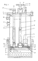
- Fig.1 die schematische Schnittdarstellung eines über einem Kühlflüsigkeitsbad angeordneten Flüssigstoffbehälters mit einer Tropfeinrichtung im unteren Bereich des Behälters,
- Fig.2 das Beispiel einer Tropfscheibe in Aufsicht, und
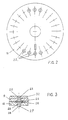
- Fig.3 die Tropfscheibe mit den eingesetzten Düsenkörpern, in vergrösserter Darstellung.
- 1 shows the schematic sectional illustration of a liquid container arranged above a cooling liquid bath with a drip device in the lower region of the container,
- 2 shows the example of a drip disc in supervision, and
- 3 shows the drip disk with the nozzle bodies used, in an enlarged view.
Die Gefriereinrichtung nach Fig. 1 besteht aus einem Behälter 1, in den das zu verarbeitende flüssige oder pastöse Produkt eingefüllt wird. Als Beispiel ist in Fig. 1 ein zylindrischer Behälter dargestellt, dessen Achse mit A-A bezeichnet ist. Der Einfüllvorgang erfolgt unter Einsatz einer Prozesssteuerung auf einen bestimmten Füllstand im Behälter. Eingefüllt wird über eine Eintragsöffnung 2. Der Füllstand wird mit einer Füllstandsanzeige 3 überwacht, die z.B. auf einen oberen und einen unteren Füllstandsgrenzwert anspricht und bei Erreichen des unteren Grenzwertes den Nachfüllvorgang auslöst und ihn bei Erreichen des oberen Füllstandes wieder abstellt.1 consists of a
Der obere Teil des Behälters 1 ist durch einen Deckel 4 abgeschlossen, der zwei an späterer Stelle näher beschriebene Verstelleinrichtungen zur Feineinstellung von Verfahrensparametern enthält. Der Deckel ist fest und unter Zwischenlage einer Dichtung 5 mit dem Behälter 1 verschraubt. Im unteren Teil ist der Behälter 1 über einen Flansch 6 auf die Halterung eines Kühlmittelbehälters 7 aufgesetzt.The upper part of the
Der untere stirnseitige Bodenabschluss des Behälters 1 wird von einer Tropfeinrichtung 8 abgeschlossen, die im wesentlichen aus zwei bündig aneinanderliegenden Scheiben 9 und 10 besteht. Im gewählten Beispiel sind beide Scheiben zentrisch zur Zylinderachse A-A angeordnet. Die behälterinnere Scheibe 9 ist als eigentlicher Behälterboden ausgebildet, gegen welchen die behälteräussere Scheibe 10 um die Zylinderachse A-A verdrehbar ist. Dazu ist die äussere Scheibe 10 an einer Zentralhülse 11 befestigt, z.B. angeschweisst. Ein an der Zentralhülse angebrachter Flanschring 12 liegt über einen O-Ring 13 an der inneren Scheibe 9 an und drückt diese unter der Wirkung einer Ringmutter 14 gegen die äussere Scheibe 10. Durch die gegenseitige Verdrehung lässt sich der wirksame Öffnungsquerschnitt von später beschriebenen Düsenkörpern verändern, welche in den Scheiben 9 und 10 angebracht sind.The lower end of the bottom end of the
In der Zentralhülse 11 ist ein Gewindeteil 15 angebracht, in welchem ein zentraler Gewindebolzen 29 läuft. Dieser Gewindebolzen ist in einer Führung 16 innerhalb des Deckels 4 unter Zwischenlage einer Dichtung 17 nach aussen geführt und mit einer Betätigungsvorrichtung 18 versehen. Dabei kann es sich um ein Handrad oder um einen gesteuerten Motorantrieb handeln. Mit Hilfe dieser Einrichtung lässt sich der Behälterboden, bestehend aus der inneren Scheibe 9 und der bündig anliegenden äusseren Scheibe 10, gezielt in der Höhe verstellen. Die Höhenverstellung erfolgt relativ zur Wand des Behälters 1 und damit relativ zum darunter befindlichen Kühlmittelbehälter 7.In the
Eine zweite Verstellachse 19 verläuft vom Deckel 4 parallel zur Zylinderachse A-A, um einen Betrag a radial zur Zylinderachse versetzt. Die von einer zweiten Betätigungsvorrichtung 20 ausgehende Drehbewegung wird auf einen Exzenter 21 am unteren Ende der Verstellachse 19 übertragen. Die Drehachse des Exzenters ist in der inneren Scheibe 9 gelagert, während der Angriffspunkt des Exzenters in der äusseren Scheibe liegt. Damit lässt sich die äussere Scheibe 10 gegenüber der inneren Scheibe 9 um die Zentralachse A-A des Behälters 1 um kleine Winkelbeträge verstellen.A
Die innere Scheibe 9 ist mit Düseneinlaufkörpern 22 versehen, welche eine Düsenbohrung 23 und auf der Seite der äusseren Scheibe eine flanschartige Verbreiterung 24 aufweisen. Im gezeigten Beispiel sind die Düseneinlaufkörper 22 in der Scheibe 9 ebenfalls leicht auswechselbar eingesetzt.The
Auf ähnliche Art sind in der äusseren Scheibe 10 auswechselbare düsenartige Abtropfkörper 25 eingesetzt, welche mit flanschartigen Verbreiterungen 26 auf der Seite der inneren Scheibe 9 versehen sind. Die flanschartigen Verbreiterungen 26 der Abtropfkörper wirken mit den Verbreiterungen 24 der Düseneinlaufkörper 22 zusammen. Durch die bündig aneinander liegenden Scheiben 9 und 10 werden die Düsenkörper in den Scheiben gehalten.In a similar way, interchangeable nozzle-
Der Abtropfkörper 25 ist mit einer Abtropfdüsenbohrung 27 und in seinem untersten Bereich mit einer besonders ausgestalteten Abtropfkante 28 versehen. Die Form der Abtropfkante kann entsprechend dem zu verarbeitenden Produkt ver schieden gestaltet sein. Die optimale Form lässt sich jeweils durch Versuche ermitteln, so dass unter den jeweils herrschenden Bedingungen ein gleichmässiger und konstanter Abriss des Flüssigkeitstropfens vom Düsenkörper gewährleistet ist. Auch der Einfluss der Oberflächenspannung kann durch unterschiedliche Materialwahl für den Abtropfkörper experimentell optimiert werden.The
Wie aus Fig. 2 ersichtlich ist, sind auf der inneren Scheibe 9 weitere Düseneinlaufkörper und auf der äusseren Scheibe 10 weitere Abtropfkörper, im Beispiel entlang eines Radius um das Zentrum der Scheiben, angeordnet. Gemeinsam bildet je ein Paar Düseneinlaufkörper und Abtropfkörper eine verstellbare Düse, wobei die Verstellung der wirksamen Düsenöffnung gemeinsam für alle Düsen mit Hilfe des Exzenters 21 erfolgt, der über die zweite Betätigungsvorrichtung 19 verstellbar ist. Damit lässt sich die Durchflussmenge auf die gewünschten Werte einstellen.As can be seen from FIG. 2, further nozzle inlet bodies are arranged on the
Die Düseneinlaufkörper 22 und die Abtropfkörper 25 sind vorzugsweise aus Edelstahl oder aus einer geeigneten Kunststoffverbindung hergestellt. Die Materialwahl richtet sich einerseits nach der Verträglichkeit mit dem zu verarbeitenden Produkt und andererseits nach den erwähnten optimalen Oberflächeneigenschaften, welche den kontrollierten Abriss der Tropfen begünstigen.The
Die in den Flüssigstoffbehälter 1 auf ein bestimmtes Niveau eingefüllte Flüssigkeit oder pastöse Masse wird unter der Wirkung des statischen Eigendrucks oder durch Beaufschlagen des Behälters mit einem Druckmedium durch die kombinierten Düsenkörper am Boden des Behälters gedrückt. Durch geeignete Wahl der Abtropfkantenform und durch Einstellung der wirksamen Düsenöffnungen und der Abtropfhöhe h (gemessen von der Oberfläche des Kühlflüssigkeitsbades) wird erreicht, dass sich die an der Abtropfkante 28 bildenden Tropfen regelmässig und in konstanter Tropfenform ablösen. Für leicht zähflüssige Massen haben sich z.B. wirksame Düsenöffnungen in der Grössenordnung zwischen 0,7 und 2,0 mm als zweckmässig erwiesen.The liquid or pasty mass filled into the
Die optimalen Werte werden, soweit sie nicht schon bekannt sind, in Vorversuchen ermittelt, zu denen sich die beschriebene Vorrichtung zusätzlich zum Produktionsbetrieb besonders gut eignet. Anstelle von Abtropfkörpern mit einheitlichen Durchmessern werden zu diesem Zweck in der äusseren Scheibe verschiedene Bereiche, z.B. verschiedene Sektoren, mit Abtropfkörpern bestückt, die abgestufte Düsendurchmesser bzw. verschiedenen Abtropfkantenformen aufweisen. Auch unterschiedliche Materialien für die Abtropfkörper können nebeneinander zum Einsatz kommen. Während eines solchen Einstellversuches werden z.B. Über eine Sichtöffnung 31 in der Wand des Kühlmittelbehälters 7 die verschiedenen Tropfenformen beobachtet, so dass sich für den nachfolgenden Produktionslauf die optimale Düsenwahl für ein neu zu verarbeitendes Produkt auf einfache Weise treffen lässt. In einer angeschlossenen Prozessteuer-Einheit lassen sich die ermittelten optimalen Daten für spätere Produktionsläufe abspeichern.Unless they are already known, the optimal values are determined in preliminary tests, for which the described device is particularly well suited in addition to the production operation. Instead of drip trays with uniform diameters, different areas, for example different sectors, are fitted with drip trays in the outer pane, which have stepped nozzle diameters or different drip edge shapes. Different materials for the drains can also be used side by side. During such an adjustment attempt, the various drop shapes are, for example, via a
Um die Funktion der Abtropfkörper wegen des darunter befindliche Kühlmittels auch im Dauerbetrieb sicherzustellen, ist der Behälterboden mit einer Heizeinrichtung 32 versehen. Damit wird der Bereich um die Abtropfkörper auf einer Temperatur gehalten, die geringfügig grösser ist als die Erstarrungstemperatur des zu verarbeitenden Produktes.In order to ensure the function of the draining bodies due to the coolant underneath, even in continuous operation, the container bottom is provided with a
Der Behälter 1 kann grundsätzlich eine beliebige Form aufweisen. Für die Verarbeitung von Sterilprodukten, insbesondere unter Anwendung der Heissluft-Sterilisierung, ist die Zylinderform von Vorteil. Die Heissluft wird z.B. über einen entsprechend gestalteten Heisslufteinlass 30 nahezu tangential in das Behälterinnere eingeführt, wodurch sich, unterstützt durch die zylinderförmige Behälterwand, eine gute Verwirbelung der Heissluft ergibt und alle Teile des Innenraums von der Heissluft erreicht werden. Auch die Düsenöffnungen werden von dem sterilisierenden Heissluftstrom erfasst.The
Claims (8)
Applications Claiming Priority (2)
| Application Number | Priority Date | Filing Date | Title |
|---|---|---|---|
| CH3473/88 | 1988-09-16 | ||
| CH3473/88A CH677141A5 (en) | 1988-09-16 | 1988-09-16 |
Publications (2)
| Publication Number | Publication Date |
|---|---|
| EP0362582A2 true EP0362582A2 (en) | 1990-04-11 |
| EP0362582A3 EP0362582A3 (en) | 1990-10-03 |
Family
ID=4256725
Family Applications (1)
| Application Number | Title | Priority Date | Filing Date |
|---|---|---|---|
| EP19890116930 Withdrawn EP0362582A3 (en) | 1988-09-16 | 1989-09-13 | Apparatus for granulating by freezing liquids |
Country Status (4)
| Country | Link |
|---|---|
| US (1) | US4967571A (en) |
| EP (1) | EP0362582A3 (en) |
| JP (1) | JPH02191538A (en) |
| CH (1) | CH677141A5 (en) |
Cited By (4)
| Publication number | Priority date | Publication date | Assignee | Title |
|---|---|---|---|---|
| AU620253B2 (en) * | 1989-05-01 | 1992-02-13 | Alkermes Controlled Therapeutics, Inc. | Process for producing small particles of biologically active molecules |
| WO1994001090A1 (en) * | 1992-07-03 | 1994-01-20 | Alfatec-Pharma Gmbh | Solid and liquid solutions of drugs which are not readily soluble in water |
| US5384129A (en) * | 1992-01-17 | 1995-01-24 | Alfatec Pharma Gmbh | Pellets containing dihydropyridine derivatives process for the production thereof and use as rapid action dosage in heart and circulatory diseases |
| US5401502A (en) * | 1992-01-17 | 1995-03-28 | Alfatec Pharma Gmbh | Pellets containing plant extracts, process of making same and their pharmaceutical peroral or cosmetic use |
Families Citing this family (19)
| Publication number | Priority date | Publication date | Assignee | Title |
|---|---|---|---|---|
| US5490505A (en) | 1991-03-07 | 1996-02-13 | Masimo Corporation | Signal processing apparatus |
| MX9702434A (en) | 1991-03-07 | 1998-05-31 | Masimo Corp | Signal processing apparatus. |
| US5776563A (en) | 1991-08-19 | 1998-07-07 | Abaxis, Inc. | Dried chemical compositions |
| US7376453B1 (en) | 1993-10-06 | 2008-05-20 | Masimo Corporation | Signal processing apparatus |
| US8019400B2 (en) | 1994-10-07 | 2011-09-13 | Masimo Corporation | Signal processing apparatus |
| EP1905352B1 (en) | 1994-10-07 | 2014-07-16 | Masimo Corporation | Signal processing method |
| US6002952A (en) | 1997-04-14 | 1999-12-14 | Masimo Corporation | Signal processing apparatus and method |
| US5893269A (en) * | 1997-06-12 | 1999-04-13 | Yale University | Crystal freezing apparatus |
| US7331186B2 (en) * | 2002-06-27 | 2008-02-19 | I.M.T. Interface Multigrad Technology Ltd | Changing the temperature of a liquid sample and a receptacle useful therefor |
| EP2548447B1 (en) | 2003-04-11 | 2017-09-27 | Cargill, Incorporated | Pellet systems for preparing beverages |
| ES2392433T3 (en) * | 2003-10-30 | 2012-12-10 | Merck Serono Sa | Procedure and apparatus for cooling and atomizing liquid or pasty substances |
| US8190223B2 (en) | 2005-03-01 | 2012-05-29 | Masimo Laboratories, Inc. | Noninvasive multi-parameter patient monitor |
| WO2008118993A1 (en) | 2007-03-27 | 2008-10-02 | Masimo Laboratories, Inc. | Multiple wavelength optical sensor |
| US8374665B2 (en) | 2007-04-21 | 2013-02-12 | Cercacor Laboratories, Inc. | Tissue profile wellness monitor |
| EP2088196A1 (en) * | 2008-02-08 | 2009-08-12 | Boehringer Ingelheim RCV GmbH & Co KG | Methods and devices for producing biomolecules |
| US9839381B1 (en) | 2009-11-24 | 2017-12-12 | Cercacor Laboratories, Inc. | Physiological measurement system with automatic wavelength adjustment |
| DE112010004682T5 (en) | 2009-12-04 | 2013-03-28 | Masimo Corporation | Calibration for multi-level physiological monitors |
| US11867460B2 (en) | 2018-06-20 | 2024-01-09 | Gen-Probe Incorporated | Method and apparatus for freezing dispensed droplets of liquid |
| CN111121375B (en) * | 2020-01-19 | 2020-12-08 | 金马工业集团股份有限公司 | Cooling device of machine |
Citations (3)
| Publication number | Priority date | Publication date | Assignee | Title |
|---|---|---|---|---|
| US2979764A (en) * | 1958-06-26 | 1961-04-18 | Olin Mathieson | Pelleting apparatus |
| US3162019A (en) * | 1962-11-16 | 1964-12-22 | Bethlehem Steel Corp | Method and apparatus for freezing liquids to be used in a freeze-drying process |
| FR2342472A1 (en) * | 1976-02-25 | 1977-09-23 | Stef | Freezing sprayed edible fluid e.g. milk, eggs, fruit juice - as fine powder ready for packaging and subsequent reconstitution |
Family Cites Families (2)
| Publication number | Priority date | Publication date | Assignee | Title |
|---|---|---|---|---|
| US3228838A (en) * | 1959-04-23 | 1966-01-11 | Union Carbide Corp | Preservation of biological substances |
| US4704873A (en) * | 1985-11-14 | 1987-11-10 | Taiyo Sanso Co., Ltd. | Method and apparatus for producing microfine frozen particles |
-
1988
- 1988-09-16 CH CH3473/88A patent/CH677141A5/de not_active IP Right Cessation
-
1989
- 1989-09-13 EP EP19890116930 patent/EP0362582A3/en not_active Withdrawn
- 1989-09-14 JP JP1237365A patent/JPH02191538A/en active Pending
- 1989-09-15 US US07/407,533 patent/US4967571A/en not_active Expired - Fee Related
Patent Citations (3)
| Publication number | Priority date | Publication date | Assignee | Title |
|---|---|---|---|---|
| US2979764A (en) * | 1958-06-26 | 1961-04-18 | Olin Mathieson | Pelleting apparatus |
| US3162019A (en) * | 1962-11-16 | 1964-12-22 | Bethlehem Steel Corp | Method and apparatus for freezing liquids to be used in a freeze-drying process |
| FR2342472A1 (en) * | 1976-02-25 | 1977-09-23 | Stef | Freezing sprayed edible fluid e.g. milk, eggs, fruit juice - as fine powder ready for packaging and subsequent reconstitution |
Cited By (5)
| Publication number | Priority date | Publication date | Assignee | Title |
|---|---|---|---|---|
| AU620253B2 (en) * | 1989-05-01 | 1992-02-13 | Alkermes Controlled Therapeutics, Inc. | Process for producing small particles of biologically active molecules |
| US5384129A (en) * | 1992-01-17 | 1995-01-24 | Alfatec Pharma Gmbh | Pellets containing dihydropyridine derivatives process for the production thereof and use as rapid action dosage in heart and circulatory diseases |
| US5401502A (en) * | 1992-01-17 | 1995-03-28 | Alfatec Pharma Gmbh | Pellets containing plant extracts, process of making same and their pharmaceutical peroral or cosmetic use |
| US5405616A (en) * | 1992-01-17 | 1995-04-11 | Alfatec Pharma Gmbh | Means for containing active substances, having a shell of hydrophilic macromolecules, active substances and process for preparation thereof |
| WO1994001090A1 (en) * | 1992-07-03 | 1994-01-20 | Alfatec-Pharma Gmbh | Solid and liquid solutions of drugs which are not readily soluble in water |
Also Published As
| Publication number | Publication date |
|---|---|
| US4967571A (en) | 1990-11-06 |
| JPH02191538A (en) | 1990-07-27 |
| EP0362582A3 (en) | 1990-10-03 |
| CH677141A5 (en) | 1991-04-15 |
Similar Documents
| Publication | Publication Date | Title |
|---|---|---|
| EP0362582A2 (en) | Apparatus for granulating by freezing liquids | |
| EP0897864B1 (en) | Apparatus and method for the dosed filling of liquid to pasty products | |
| DE2330641C2 (en) | Device for discharging items to be treated from a treatment room | |
| DD266276A5 (en) | DENSITY LUBRICANTS FOR HIGH-VISCOSE LIQUIDS | |
| CH463024A (en) | Method and device for disinfecting equipment and instruments | |
| EP0134944B1 (en) | Apparatus for obtaining granules | |
| EP0284837B1 (en) | Device for rapid and uniform freezing of viscous liquids | |
| EP3219383B1 (en) | Drum coater for applying a surface layer on piece good materials | |
| DE2541939A1 (en) | HORIZONTAL CONTINUOUS KNABLES FOR HIGHLY VISCOSE MATERIAL | |
| DE102007028912A1 (en) | Procedure for drying of granulates or pellets e.g.tablets, pills and capsules in a container with circular cross-section and tappet arranged in the container, comprises rotatably driving the container around its longitudinal axis | |
| DE3417372C2 (en) | ||
| EP0744212A2 (en) | Coating drum | |
| EP0756572A1 (en) | Device for metered extraction of bulk solids | |
| DE19932623C2 (en) | Method and device for storing and / or degassing viscous liquids, in particular cast resin | |
| DE2840481A1 (en) | THICK LAYER CONTACT DRYER | |
| DE1034585B (en) | Process and device for evaporation of liquids | |
| EP0523335B1 (en) | Process for applying as stripes or drops liquid masses on an conveyor belt | |
| DE345313C (en) | Process for disinfecting milk and other liquids by the action of heat, in which the liquid is spread out in thin layers on fixed or rotating surfaces for the purpose of disinfection | |
| DE4244035C1 (en) | Granulate mfr. assembly with reduced molten material leakage and enhanced safety - incorporates bearing bell seals to rotating section | |
| DE624279C (en) | Process and device for transferring liquefied salts, alkalis and similar materials into almost spherical granules | |
| WO2003011447A1 (en) | Device for extruding flowable compounds and method for producing such a device | |
| DE831468C (en) | Device for discharging grit from storage containers | |
| DE362331C (en) | Device for sterilizing milk and other liquids | |
| CH269791A (en) | Device for high vacuum distillation. | |
| DE1940890C (en) | centrifuge |
Legal Events
| Date | Code | Title | Description |
|---|---|---|---|
| PUAI | Public reference made under article 153(3) epc to a published international application that has entered the european phase |
Free format text: ORIGINAL CODE: 0009012 |
|
| AK | Designated contracting states |
Kind code of ref document: A2 Designated state(s): AT BE DE ES FR GB IT NL SE |
|
| PUAL | Search report despatched |
Free format text: ORIGINAL CODE: 0009013 |
|
| AK | Designated contracting states |
Kind code of ref document: A3 Designated state(s): AT BE DE ES FR GB IT NL SE |
|
| RHK1 | Main classification (correction) |
Ipc: B01J 2/02 |
|
| 17P | Request for examination filed |
Effective date: 19901016 |
|
| 17Q | First examination report despatched |
Effective date: 19910228 |
|
| STAA | Information on the status of an ep patent application or granted ep patent |
Free format text: STATUS: THE APPLICATION IS DEEMED TO BE WITHDRAWN |
|
| 18D | Application deemed to be withdrawn |
Effective date: 19910711 |