EP0362171A2 - Double-sided cutting insert - Google Patents
Double-sided cutting insert Download PDFInfo
- Publication number
- EP0362171A2 EP0362171A2 EP89850306A EP89850306A EP0362171A2 EP 0362171 A2 EP0362171 A2 EP 0362171A2 EP 89850306 A EP89850306 A EP 89850306A EP 89850306 A EP89850306 A EP 89850306A EP 0362171 A2 EP0362171 A2 EP 0362171A2
- Authority
- EP
- European Patent Office
- Prior art keywords
- cutting
- face
- insert
- chip
- cutting insert
- Prior art date
- Legal status (The legal status is an assumption and is not a legal conclusion. Google has not performed a legal analysis and makes no representation as to the accuracy of the status listed.)
- Granted
Links
Images


Classifications
-
- B—PERFORMING OPERATIONS; TRANSPORTING
- B23—MACHINE TOOLS; METAL-WORKING NOT OTHERWISE PROVIDED FOR
- B23B—TURNING; BORING
- B23B27/00—Tools for turning or boring machines; Tools of a similar kind in general; Accessories therefor
- B23B27/14—Cutting tools of which the bits or tips or cutting inserts are of special material
- B23B27/16—Cutting tools of which the bits or tips or cutting inserts are of special material with exchangeable cutting bits or cutting inserts, e.g. able to be clamped
-
- B—PERFORMING OPERATIONS; TRANSPORTING
- B23—MACHINE TOOLS; METAL-WORKING NOT OTHERWISE PROVIDED FOR
- B23B—TURNING; BORING
- B23B27/00—Tools for turning or boring machines; Tools of a similar kind in general; Accessories therefor
- B23B27/14—Cutting tools of which the bits or tips or cutting inserts are of special material
- B23B27/141—Specially shaped plate-like cutting inserts, i.e. length greater or equal to width, width greater than or equal to thickness
- B23B27/143—Specially shaped plate-like cutting inserts, i.e. length greater or equal to width, width greater than or equal to thickness characterised by having chip-breakers
-
- Y—GENERAL TAGGING OF NEW TECHNOLOGICAL DEVELOPMENTS; GENERAL TAGGING OF CROSS-SECTIONAL TECHNOLOGIES SPANNING OVER SEVERAL SECTIONS OF THE IPC; TECHNICAL SUBJECTS COVERED BY FORMER USPC CROSS-REFERENCE ART COLLECTIONS [XRACs] AND DIGESTS
- Y10—TECHNICAL SUBJECTS COVERED BY FORMER USPC
- Y10T—TECHNICAL SUBJECTS COVERED BY FORMER US CLASSIFICATION
- Y10T407/00—Cutters, for shaping
- Y10T407/23—Cutters, for shaping including tool having plural alternatively usable cutting edges
- Y10T407/235—Cutters, for shaping including tool having plural alternatively usable cutting edges with integral chip breaker, guide or deflector
-
- Y—GENERAL TAGGING OF NEW TECHNOLOGICAL DEVELOPMENTS; GENERAL TAGGING OF CROSS-SECTIONAL TECHNOLOGIES SPANNING OVER SEVERAL SECTIONS OF THE IPC; TECHNICAL SUBJECTS COVERED BY FORMER USPC CROSS-REFERENCE ART COLLECTIONS [XRACs] AND DIGESTS
- Y10—TECHNICAL SUBJECTS COVERED BY FORMER USPC
- Y10T—TECHNICAL SUBJECTS COVERED BY FORMER US CLASSIFICATION
- Y10T407/00—Cutters, for shaping
- Y10T407/24—Cutters, for shaping with chip breaker, guide or deflector
Definitions
- the present invention relates to a double-sided cutting insert for chipforming machining consisting of a body of generally polygonal shape having an upper face defining a rake face and a lower face, said faces being essentially identical, and side faces intersecting said upper rake face and said lower face to form cutting edges, two of said side faces meeting each other in a cutting corner.
- Each of said upper and lower faces is provided with a central depression.
- a double-sided cutting insert for chipforming machining is disclosed in US-Patent 4,312,250 in which each upper and lower face of the insert has a centrally raised portion for the purpose of giving the insert an adequate support surface when located against a bottom support.
- the cutting edge provided at the lower face and its adjacent chip face are arranged at some distance from the bottom support and the insert is therefore susceptible to failure when subjected to large tensile forces.
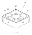
- Figs. 1 - 5 show a cutting insert 10 according to this invention, preferably for a lathe cutting tool.
- the insert 10 is manufactured of a ceramic material or cemented carbide or a similar material.
- the insert is in the form of a body of generally polygonal shape; in this case it has rhombic basic shape and has a central aperture for clamping purpose.
- the insert includes an upper face 11 and an opposite bottom face 12 which are mainly identical.
- the faces 11 and 12 intersect with continuously extending side surfaces 13 to 16 to define cutting edges 17 to 20 along the periphery of said upper face 11 and said bottom face 12.
- the side surfaces 13-16 meet at rounded cutting corners 21.
- the cutting corner 21 defines a bisector B.
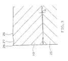
- Each side has a central depression 22 which slopes downwards and inwards at an angle ⁇ from chip faces 23 and from their corner portions 24.
- the angle ⁇ is selected in the range 0.5° - 8°.
- Each face 23 is mainly perpendicular towards the side surfaces 13-16 and is intended for chip upsetting during machining.
- the corner portions 24 are arranged in a plane P.
- Each corner portion 24 is oriented perpendicular in relation to the adjacent side surfaces 13-16 and is intended, in an active position, to upset chips in similarity with the face 23.
- the face 23 is provided with a certain play 28 from the plane P or the bottom support 25. This play 28 is in the order of 0.05 - 0.5 mm.
- the face 23 and corner portion 24, via a surrounding negative bevelled face 26, are directly or indirectly connected with the cutting edges 17.
- the corner portions 24 are symmetrically arranged in relation to the bisector B of the adjacent cutting corner 21.
- the largest width of the cutting corner in a direction parallel with said bisector B is larger than the largest width of the face 23 as seen perpendicular to adjacent cutting edge.
- Each of the cutting corners 21 is provided with a depression 27 which is arranged symmetrically in relation to the bisector B of said corner. This depression intersects with the bevelled face 26 and extends inwardly from said bevelled face and occupies about half of the length of the corner portion 24 as seen in the length direction of the bisector.
- the largest width of the depression perpendicularly from said bisector is less than the largest width of said corner portion in the same direction.
- Figs. 6 and 7 illustrate an alternative embodiment of an insert 10′ of this invention.
- the insert has a shape identical with insert 10 with the exception, however, that the corner portions 24′ and the faces 23 are located in the same plane P.
- the insert 10′ is intended to abut against a support along the entire periphery of the insert whereby the support surfaces of the insert are arragend in the most favourable position.
- the insert 10 and 10′ of this invention is preferably provided with the negative bevelled face 26 and 26′ in those cases when the insert is to be made of ceramics or a corresponding material susceptible to tensile forces. If the insert is to be made of cemented carbide the faces 23 and 23′ and corner portions 24 and 24′ will preferably be connected directly with the adjacent cutting edge 17-20 and 17′-20′.
- the inserts 10 and 10′ can also be provided with projections in the chip face 23, 24 and 23′, 24′ of the type being described in SE-A-8803354-3 which is herein incorporated in terms of its description.
- the present invention thus relates to a double-sided insert for chipforming machining of the type wherein the insert has combined support and chip faces which are so designed that the risk for cracking failure is minimized.
Abstract
Description
- The present invention relates to a double-sided cutting insert for chipforming machining consisting of a body of generally polygonal shape having an upper face defining a rake face and a lower face, said faces being essentially identical, and side faces intersecting said upper rake face and said lower face to form cutting edges, two of said side faces meeting each other in a cutting corner. Each of said upper and lower faces is provided with a central depression.
- A double-sided cutting insert for chipforming machining is disclosed in US-Patent 4,312,250 in which each upper and lower face of the insert has a centrally raised portion for the purpose of giving the insert an adequate support surface when located against a bottom support. The cutting edge provided at the lower face and its adjacent chip face are arranged at some distance from the bottom support and the insert is therefore susceptible to failure when subjected to large tensile forces.
- It is an object of the present invention to provide a double-sided cutting insert with as good strength as possible during machining.
- It is another object of the present invention to provide a cutting insert equipped with a plurality of cutting edges.
- These and other objects are achieved by the characterizing features outlined in the following patent claims.
- The invention will now be described more in detail with reference to the accompanying drawings showing:
- Fig. 1, a plan view of a cutting insert according to the invention;
- Fig. 2, a side view of the insert of Fig. 1;
- Fig. 3, a partial sectional enlarged view along the line III-III in Fig. 1, in which a portion of a bottom support is shown adjacent the insert;
- Fig. 4, a partial sectional enlarged view along the line IV-IV in Fig. 1, in which a portion of a bottom support is shown adjacent the insert;
- Fig. 5, a perspective view of the insert in Fig. 1;
- Figs. 6 and 7, an alternative embodiment of an insert of the invention as shown in plan view and in a side view, respectively.
- Figs. 1 - 5 show a
cutting insert 10 according to this invention, preferably for a lathe cutting tool. Theinsert 10 is manufactured of a ceramic material or cemented carbide or a similar material. The insert is in the form of a body of generally polygonal shape; in this case it has rhombic basic shape and has a central aperture for clamping purpose. The insert includes an upper face 11 and anopposite bottom face 12 which are mainly identical. Thefaces 11 and 12 intersect with continuously extendingside surfaces 13 to 16 to definecutting edges 17 to 20 along the periphery of said upper face 11 and saidbottom face 12. The side surfaces 13-16 meet atrounded cutting corners 21. Thecutting corner 21 defines a bisector B. Each side has acentral depression 22 which slopes downwards and inwards at an angle α fromchip faces 23 and from theircorner portions 24. The angle α is selected in the range 0.5° - 8°. Eachface 23 is mainly perpendicular towards the side surfaces 13-16 and is intended for chip upsetting during machining. Thecorner portions 24 are arranged in a plane P. Eachcorner portion 24 is oriented perpendicular in relation to the adjacent side surfaces 13-16 and is intended, in an active position, to upset chips in similarity with theface 23. Theface 23 is provided with acertain play 28 from the plane P or thebottom support 25. Thisplay 28 is in the order of 0.05 - 0.5 mm. Theface 23 andcorner portion 24, via a surrounding negative bevelledface 26, are directly or indirectly connected with thecutting edges 17. Thecorner portions 24 are symmetrically arranged in relation to the bisector B of theadjacent cutting corner 21. The largest width of the cutting corner in a direction parallel with said bisector B is larger than the largest width of theface 23 as seen perpendicular to adjacent cutting edge. Each of thecutting corners 21 is provided with adepression 27 which is arranged symmetrically in relation to the bisector B of said corner. This depression intersects with thebevelled face 26 and extends inwardly from said bevelled face and occupies about half of the length of thecorner portion 24 as seen in the length direction of the bisector. The largest width of the depression perpendicularly from said bisector is less than the largest width of said corner portion in the same direction. - Figs. 6 and 7 illustrate an alternative embodiment of an
insert 10′ of this invention. The insert has a shape identical withinsert 10 with the exception, however, that thecorner portions 24′ and thefaces 23 are located in the same plane P. Theinsert 10′ is intended to abut against a support along the entire periphery of the insert whereby the support surfaces of the insert are arragend in the most favourable position. - The
insert bevelled face faces corner portions - The
inserts chip face - The present invention thus relates to a double-sided insert for chipforming machining of the type wherein the insert has combined support and chip faces which are so designed that the risk for cracking failure is minimized.
Claims (9)
Priority Applications (1)
| Application Number | Priority Date | Filing Date | Title |
|---|---|---|---|
| AT89850306T ATE102101T1 (en) | 1988-09-26 | 1989-09-19 | DOUBLE-SIDED CUTTING INSERT. |
Applications Claiming Priority (2)
| Application Number | Priority Date | Filing Date | Title |
|---|---|---|---|
| SE8803389A SE465958B (en) | 1988-09-26 | 1988-09-26 | DOUBLE SIDE CUT |
| SE8803389 | 1988-09-26 |
Publications (3)
| Publication Number | Publication Date |
|---|---|
| EP0362171A2 true EP0362171A2 (en) | 1990-04-04 |
| EP0362171A3 EP0362171A3 (en) | 1990-08-22 |
| EP0362171B1 EP0362171B1 (en) | 1994-03-02 |
Family
ID=20373432
Family Applications (1)
| Application Number | Title | Priority Date | Filing Date |
|---|---|---|---|
| EP89850306A Expired - Lifetime EP0362171B1 (en) | 1988-09-26 | 1989-09-19 | Double-sided cutting insert |
Country Status (8)
| Country | Link |
|---|---|
| US (1) | US5011340A (en) |
| EP (1) | EP0362171B1 (en) |
| JP (1) | JPH02180508A (en) |
| KR (1) | KR900004445A (en) |
| CN (1) | CN1020422C (en) |
| AT (1) | ATE102101T1 (en) |
| DE (1) | DE68913414T2 (en) |
| SE (1) | SE465958B (en) |
Cited By (3)
| Publication number | Priority date | Publication date | Assignee | Title |
|---|---|---|---|---|
| US5116167A (en) * | 1991-02-19 | 1992-05-26 | Kennametal Inc. | Cutting insert with chip control |
| EP2440351A1 (en) * | 2009-06-10 | 2012-04-18 | TaeguTec Ltd. | Cutting tool and cutting insert for the same |
| US9623493B2 (en) * | 2008-11-19 | 2017-04-18 | Kennametal Inc. | Double-sided ball end mill cutting insert and tool therefor |
Families Citing this family (17)
| Publication number | Priority date | Publication date | Assignee | Title |
|---|---|---|---|---|
| IL101985A (en) * | 1992-05-25 | 1996-12-05 | Iscar Ltd | Exchangeable milling cutting inserts |
| IL104273A (en) * | 1992-12-30 | 1996-01-31 | Iscar Ltd | Double faced cutting insert |
| DE29822553U1 (en) * | 1998-12-18 | 1999-03-04 | Widia Gmbh | Cutting insert and tool with cutting insert |
| SE515070C2 (en) * | 1999-10-22 | 2001-06-05 | Sandvik Ab | Double negative cutting tool for chip separating machining |
| JP4676655B2 (en) * | 2001-07-19 | 2011-04-27 | ユニタック株式会社 | Throwaway drill for deep hole cutting |
| SE527378C2 (en) * | 2003-05-08 | 2006-02-21 | Sandvik Intellectual Property | Cutters for turning have an edge phase |
| SE529067C2 (en) * | 2004-08-25 | 2007-04-24 | Seco Tools Ab | Turning inserts with cutting hole arrangement with two shafts |
| KR100698383B1 (en) * | 2005-03-23 | 2007-03-23 | 한국야금 주식회사 | Milling Cutting tool having a double sides cutting insert |
| CN100417476C (en) * | 2005-12-02 | 2008-09-10 | 株洲钻石切削刀具股份有限公司 | Transposable turning tool blade for working high-hardness, high-viscosity material |
| DE102006017074A1 (en) * | 2006-04-10 | 2007-10-11 | Walter Ag | Shim for double-sided indexable inserts |
| WO2008142096A1 (en) * | 2007-05-24 | 2008-11-27 | Ceramtec Ag | Cutting insert comprising a stabilising double-sided facet |
| SE531508C2 (en) * | 2007-08-31 | 2009-05-05 | Sandvik Intellectual Property | Cut for chip separating machining with a wipe segment |
| EP3006140B1 (en) * | 2014-10-08 | 2017-04-19 | Sandvik Intellectual Property AB | Turning tool cutting insert and turning tool |
| EP3260225B1 (en) * | 2016-06-20 | 2022-11-30 | Sandvik Intellectual Property AB | Turning insert |
| US10710167B2 (en) * | 2017-08-02 | 2020-07-14 | Iscar, Ltd. | Negative finish turning insert with chip forming arrangement |
| JP2020069598A (en) * | 2018-10-31 | 2020-05-07 | 京セラ株式会社 | Cutting insert, cutting tool and manufacturing method for cutting work-piece |
| CN114309682A (en) | 2020-09-30 | 2022-04-12 | 肯纳金属公司 | Cutting insert |
Citations (7)
| Publication number | Priority date | Publication date | Assignee | Title |
|---|---|---|---|---|
| US3395434A (en) * | 1966-06-01 | 1968-08-06 | Sandvikens Jernverks Ab | Cutting insert for chip cutting machining |
| US3875663A (en) * | 1971-11-12 | 1975-04-08 | Seco Tools Ab | Indexable cutting insert |
| US4312250A (en) * | 1980-01-16 | 1982-01-26 | Yankoff Gerald K | Cutting insert and method of machining therewith |
| GB2092032A (en) * | 1981-01-30 | 1982-08-11 | Kennametal Inc | Cutting insert |
| DE3332821A1 (en) * | 1982-11-29 | 1984-05-30 | Veb Werkzeugkombinat Schmalkalden, Ddr 6080 Schmalkalden | Indexable insert with chip-forming and chip-breaking recesses |
| US4507024A (en) * | 1982-09-30 | 1985-03-26 | Gte Valeron Corporation | Cutting insert with chip control |
| DD250273A1 (en) * | 1986-06-26 | 1987-10-08 | Immelborn Hartmetallwerk | INSERTION CIRCUIT PLATE WITH SPANISH CRASHES |
Family Cites Families (9)
| Publication number | Priority date | Publication date | Assignee | Title |
|---|---|---|---|---|
| JPS4854999A (en) * | 1971-11-08 | 1973-08-02 | ||
| JPS5325351B2 (en) * | 1973-08-02 | 1978-07-26 | ||
| JPS5822725B2 (en) * | 1979-10-22 | 1983-05-11 | 日本電信電話株式会社 | optical demultiplexer |
| US4318645A (en) * | 1980-09-02 | 1982-03-09 | Kennametal Inc. | Cutting insert |
| JPS59162105A (en) * | 1983-03-04 | 1984-09-13 | Nippon Kokan Kk <Nkk> | Recovery of hydrochloric acid from waste liquor of hydrochloric acid |
| CA1231612A (en) * | 1984-06-19 | 1988-01-19 | Anthony J. Bruegge | Stabilized active halogen-containing detergent compositions and methods |
| US4626141A (en) * | 1985-01-23 | 1986-12-02 | Gte Valeron Corporation | Chip control insert |
| JPS61288903A (en) * | 1985-06-14 | 1986-12-19 | Mitsubishi Metal Corp | No-grinding negative throw away tip |
| DD260238A1 (en) * | 1987-05-06 | 1988-09-21 | Immelborn Hartmetallwerk | CUTTING PLATE WITH MOLDING CROP |
-
1988
- 1988-09-26 SE SE8803389A patent/SE465958B/en not_active IP Right Cessation
-
1989
- 1989-09-19 DE DE68913414T patent/DE68913414T2/en not_active Expired - Lifetime
- 1989-09-19 AT AT89850306T patent/ATE102101T1/en not_active IP Right Cessation
- 1989-09-19 EP EP89850306A patent/EP0362171B1/en not_active Expired - Lifetime
- 1989-09-25 CN CN89107482A patent/CN1020422C/en not_active Expired - Lifetime
- 1989-09-25 JP JP1246589A patent/JPH02180508A/en active Pending
- 1989-09-26 KR KR1019890013814A patent/KR900004445A/en not_active Application Discontinuation
- 1989-09-26 US US07/413,005 patent/US5011340A/en not_active Expired - Lifetime
Patent Citations (7)
| Publication number | Priority date | Publication date | Assignee | Title |
|---|---|---|---|---|
| US3395434A (en) * | 1966-06-01 | 1968-08-06 | Sandvikens Jernverks Ab | Cutting insert for chip cutting machining |
| US3875663A (en) * | 1971-11-12 | 1975-04-08 | Seco Tools Ab | Indexable cutting insert |
| US4312250A (en) * | 1980-01-16 | 1982-01-26 | Yankoff Gerald K | Cutting insert and method of machining therewith |
| GB2092032A (en) * | 1981-01-30 | 1982-08-11 | Kennametal Inc | Cutting insert |
| US4507024A (en) * | 1982-09-30 | 1985-03-26 | Gte Valeron Corporation | Cutting insert with chip control |
| DE3332821A1 (en) * | 1982-11-29 | 1984-05-30 | Veb Werkzeugkombinat Schmalkalden, Ddr 6080 Schmalkalden | Indexable insert with chip-forming and chip-breaking recesses |
| DD250273A1 (en) * | 1986-06-26 | 1987-10-08 | Immelborn Hartmetallwerk | INSERTION CIRCUIT PLATE WITH SPANISH CRASHES |
Non-Patent Citations (2)
| Title |
|---|
| WERKSTATT UND BETRIEB vol.114, no. 5, May 1981, München, D. H.D. SCHUBERT : "Auswahl geeigneter Spanbrecherformen bei Wendeschneidplatten". page 295, figures 2, 3, position M-37* * |
| WERKSTATT UND BETRIEB, Vol. 114, No. 5, May 1981, Pages 295-298, München, D; H.D. SCHUBERT: "Auswahl geeigneter Spanbrecherformen bei Wendeschneidplatten". * |
Cited By (4)
| Publication number | Priority date | Publication date | Assignee | Title |
|---|---|---|---|---|
| US5116167A (en) * | 1991-02-19 | 1992-05-26 | Kennametal Inc. | Cutting insert with chip control |
| US9623493B2 (en) * | 2008-11-19 | 2017-04-18 | Kennametal Inc. | Double-sided ball end mill cutting insert and tool therefor |
| EP2440351A1 (en) * | 2009-06-10 | 2012-04-18 | TaeguTec Ltd. | Cutting tool and cutting insert for the same |
| EP2440351A4 (en) * | 2009-06-10 | 2012-11-21 | Taegu Tec Ltd | Cutting tool and cutting insert for the same |
Also Published As
| Publication number | Publication date |
|---|---|
| EP0362171A3 (en) | 1990-08-22 |
| SE8803389D0 (en) | 1988-09-26 |
| JPH02180508A (en) | 1990-07-13 |
| DE68913414D1 (en) | 1994-04-07 |
| ATE102101T1 (en) | 1994-03-15 |
| KR900004445A (en) | 1990-04-12 |
| EP0362171B1 (en) | 1994-03-02 |
| DE68913414T2 (en) | 1994-06-01 |
| SE8803389L (en) | 1990-03-27 |
| US5011340A (en) | 1991-04-30 |
| CN1020422C (en) | 1993-05-05 |
| SE465958B (en) | 1991-11-25 |
| CN1042676A (en) | 1990-06-06 |
Similar Documents
| Publication | Publication Date | Title |
|---|---|---|
| EP0362171A2 (en) | Double-sided cutting insert | |
| KR0139417B1 (en) | Cutting insert for chip forming machining | |
| US5044840A (en) | Indexable cutting insert | |
| US5222843A (en) | Insert for light feed, light depth of cut | |
| US6599061B1 (en) | Cutting insert with radially aligned chip forming grooves | |
| JP3607288B2 (en) | Cutting insert with tip control means | |
| US4915548A (en) | Cutting insert with raised cutting edge | |
| US7121772B2 (en) | Cutting insert | |
| KR100437433B1 (en) | Cutting insert and holder for metal cutting machining | |
| US4880338A (en) | Cutting insert | |
| US6241430B1 (en) | Cutting insert having a chip former | |
| EP0577573B1 (en) | Cutting insert for chipforming machining | |
| EP0232692B1 (en) | Indexable cutting insert | |
| US5007775A (en) | Cutting insert for chip removing machining | |
| US4487534A (en) | Polygonal cutting bit | |
| US5265985A (en) | Metal cutting insert | |
| US5000626A (en) | Cutting insert for low ranges of feed and depth of cut | |
| JPS629812A (en) | Inserted blade for cutting | |
| EP0916439B1 (en) | Throwaway insert for ball end mill | |
| US4674924A (en) | Single-sided cutting insert | |
| EP0313044B1 (en) | Cutting insert | |
| WO2000038866A9 (en) | Cutting insert with chip control | |
| EP0462954B1 (en) | Ball end mill and throw away insert for such end mill | |
| EP0168555B1 (en) | Throwaway insert | |
| US5599141A (en) | Chip control insert |
Legal Events
| Date | Code | Title | Description |
|---|---|---|---|
| PUAI | Public reference made under article 153(3) epc to a published international application that has entered the european phase |
Free format text: ORIGINAL CODE: 0009012 |
|
| AK | Designated contracting states |
Kind code of ref document: A2 Designated state(s): AT BE CH DE ES FR GB IT LI LU NL SE |
|
| PUAL | Search report despatched |
Free format text: ORIGINAL CODE: 0009013 |
|
| AK | Designated contracting states |
Kind code of ref document: A3 Designated state(s): AT BE CH DE ES FR GB IT LI LU NL SE |
|
| 17P | Request for examination filed |
Effective date: 19901224 |
|
| 17Q | First examination report despatched |
Effective date: 19920218 |
|
| GRAA | (expected) grant |
Free format text: ORIGINAL CODE: 0009210 |
|
| ITF | It: translation for a ep patent filed |
Owner name: BARZANO' E ZANARDO MILANO S.P.A. |
|
| AK | Designated contracting states |
Kind code of ref document: B1 Designated state(s): AT BE CH DE ES FR GB IT LI LU NL SE |
|
| PG25 | Lapsed in a contracting state [announced via postgrant information from national office to epo] |
Ref country code: SE Free format text: THE PATENT HAS BEEN ANNULLED BY A DECISION OF A NATIONAL AUTHORITY Effective date: 19940302 Ref country code: NL Effective date: 19940302 Ref country code: LI Effective date: 19940302 Ref country code: ES Free format text: THE PATENT HAS BEEN ANNULLED BY A DECISION OF A NATIONAL AUTHORITY Effective date: 19940302 Ref country code: CH Effective date: 19940302 Ref country code: AT Effective date: 19940302 Ref country code: BE Effective date: 19940302 |
|
| REF | Corresponds to: |
Ref document number: 102101 Country of ref document: AT Date of ref document: 19940315 Kind code of ref document: T |
|
| REF | Corresponds to: |
Ref document number: 68913414 Country of ref document: DE Date of ref document: 19940407 |
|
| REG | Reference to a national code |
Ref country code: CH Ref legal event code: PL |
|
| ET | Fr: translation filed | ||
| NLV1 | Nl: lapsed or annulled due to failure to fulfill the requirements of art. 29p and 29m of the patents act | ||
| PG25 | Lapsed in a contracting state [announced via postgrant information from national office to epo] |
Ref country code: LU Free format text: LAPSE BECAUSE OF NON-PAYMENT OF DUE FEES Effective date: 19940930 |
|
| PLBE | No opposition filed within time limit |
Free format text: ORIGINAL CODE: 0009261 |
|
| STAA | Information on the status of an ep patent application or granted ep patent |
Free format text: STATUS: NO OPPOSITION FILED WITHIN TIME LIMIT |
|
| 26N | No opposition filed | ||
| REG | Reference to a national code |
Ref country code: GB Ref legal event code: IF02 |
|
| REG | Reference to a national code |
Ref country code: GB Ref legal event code: 732E |
|
| REG | Reference to a national code |
Ref country code: GB Ref legal event code: 732E |
|
| REG | Reference to a national code |
Ref country code: FR Ref legal event code: TP |
|
| REG | Reference to a national code |
Ref country code: FR Ref legal event code: TP |
|
| PGFP | Annual fee paid to national office [announced via postgrant information from national office to epo] |
Ref country code: IT Payment date: 20080926 Year of fee payment: 20 Ref country code: FR Payment date: 20080915 Year of fee payment: 20 |
|
| PGFP | Annual fee paid to national office [announced via postgrant information from national office to epo] |
Ref country code: GB Payment date: 20080924 Year of fee payment: 20 |
|
| PGFP | Annual fee paid to national office [announced via postgrant information from national office to epo] |
Ref country code: DE Payment date: 20081002 Year of fee payment: 20 |
|
| REG | Reference to a national code |
Ref country code: GB Ref legal event code: PE20 Expiry date: 20090918 |
|
| PG25 | Lapsed in a contracting state [announced via postgrant information from national office to epo] |
Ref country code: GB Free format text: LAPSE BECAUSE OF EXPIRATION OF PROTECTION Effective date: 20090918 |